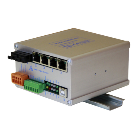
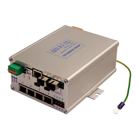
Metel 2G 2S.0.3.F Operating and maintenance instructions

www.metel.eu 1/23
www.iplog.eu
REV-202204
Industrial PoE+ Managed witches 2G
2 .0.3.F
2G
2 .0.3.F PoE NMPMODBU VLAN R TPONVIF 802.1X
Typical connection
2G-2 .0.3.F-BOX-PoE
LAN-RING 20G
LAN-RING 2G
For Available FP Modules Visit www.metel.eu
2G-2 .0.3.F-BOX-PoE 2 0 3 2 1 2
AVAILABLE PORT : FP GE FE D/AI RELAY R 485
upply without PoE 10-60VDC/10-30VAC, with PoE 48-57VDC
upply with PoE+ 52-57VDC (15…25W), with PoE++ 53-57VDC (>25W)
2G-2 .0.3.F-BOX-PoE 1-988-220 10-60VDC/10-30VAC
Holder for Mounting to DIN35 and Flat urface is Included.
PRODUCT NAME CODE NOTE
Vertical Mounting to DIN35 Mounting to a Flat urfaceMounting to DIN35
v 2x FP lot with upport of 100/1000BA E-X
v 3x Fast Ethernet Port with PoE IEEE 802.3af/at
max. 30W per Port
v Total PoE Power Over All Ports is 90W
v 2x R 485/Modbus-RTU Buses
v 2x Digital/Alarm Inputs
v 1x Programmable Relay Output
v 2 Independent Power Inputs
v Redundant Topology LAN-RING, R TP
v Event Management with upport:
HTTP/ONVIF Client, E-mail, IP Watchdogs, ETH
Events, TCP, Modbus, DIO, Balanced Loops…
v Visualization oftware upport
v Encrypted Management via LAN/Local U B
v urge Protectors up to 150A (8/20µs)
v VLAN, Qo , NMP, MTP, NTP, IGMP, R TP,
LLDP, 802.1X, Mirror, Remote Acces IP Table
v Maximum tart Time 15s
v Operating Range −40°C to + 70°C
v Operating Range of Components -40°C to + 85°C
LAN-RING 2G
1x MM / M Fiber Fast Ethernet erial Buses Other IO
Gigabit Ethernet Fast Ethernet with PoE
I&HAS
& ACS
REDO AO
AI DI
Modbus RTU
RE DOAOAIDI
RE
DO
AO
AI DI RE
DO
AO
AI DI
I&HAS
& ACS
Modbus RTU
Typical Connection of LAN-RING ystem Versatility

www.metel.eu 2/23
www.iplog.eu
REV-202204
Industrial PoE+ Managed witches 2G
2 .0.3.F
2G
2 .0.3.F PoE NMPMODBU VLAN R TPONVIF 802.1X
Further
info
pages
12 - 13
16 - 18
Further
info
pages
15,
21 - 22
BX-100-20-W4-L 4-101-020 C / PC 20 / 5 km
BX-100-20-W5-L 4-101-010 C / PC 20 / 5 km
BX-1000-20-W4-L 4-101-120 C / PC 20 / 2 km
BX-1000-20-W5-L 4-101-110 C / PC 20 / 2 km
BX-1000-60-W4-L 4-101-122 C / PC 60 / - km
BX-1000-60-W5-L 4-101-112 C / PC 60 / - km
PRODUCT NAME CODE CONNECTOR RANGE(1)
2x FP lots with 100/1000BA E-X upport
Switches 2G-2S.0.3.F have 2 SFP slots universally usable
both for SFP modules ME EL (tab on the right) and for SFP
modules of other manufacturers. he main advantages of
ME EL SFP modules are:
- bidirectional CWDM data transmission over one fiber
- used components with a range from −40 to +85°C
- SM / MM universal (all versions -20-)
- minimum warranty period 5 years (1) singlemode (9/125µm) / multimode (50/125µm)
3x Fast Ethernet Port with PoE up to 30W per Port
Fast Ethernet ports support 10BASE- , 100BASE- standards including Auto negotiation,
MDI/MDI-X and PoE standards 802.3af/at up to 30W per port. he distri-bution of power to
individual ports is set in the Simuland.v4 application. he ports due to increased reliability
are protected by surge protection up to 150A in a floating connection.
& The maximum total power consumption of PoE over all ports is 90W.
2x R 485/Modbus-RTU Buses
he switches are equipped with two RS485 buses enabling the connection of Modbus R U IO
modules and sensors, selected types of I&HAS systems and other devices.
& The transmission of system buses of I&HA systems is certified according to EN50131-1.
Further
info
page
8-9
2x Digital/Alarm Inputs
Digital/alarm inputs are mainly used for connecting button tampers, PIR sensors and others.
SIMUland management software allows them to be used to set up a range of automatic
actions. In addition, the inputs are monitorable via the SNMP protocol.
Further
info
page
14
1x Programmable Relay Output
Programmable relay output is used to signal faults (eg open circuit), control el. locks,
contactors and signaling elements. In addition, the relay can be controlled from software
superstructures, IPLOG PLC SNMP or MODBUS protocol, or EVEN MANAGEN switches.
Further
info
page
18
2 Independent Power Inputs
he switches have 2 independent power inputs 10 to 60VDC and one 10-30VAC input.
ypical applications with backup power supply are systems where the switch is part of the IP
CC V system and at the same time transmits the system bus of the PZ S system. he inputs
are protected against overvoltage.
Further
info
page
5
LAN / U B Management
In addition to secure LAN management, each LAN-RING switch has a USB-A connector for
local management via the SIMULand application. he USB connector also allows you to reset
the switch to factory settings. he inputs are protected against overvoltage.

www.metel.eu 3/23
www.iplog.eu
REV-202204
Industrial PoE+ Managed witches 2G
2 .0.3.F
2G
2 .0.3.F PoE NMPMODBU VLAN R TPONVIF 802.1X
upported Formats 100/1000 BA E-LX, BA E-BX M A Compatibility
FP lots Number 2
LAN Number 3 FE
Overvoltage Protection FE ports: up to 150 A in the wave 8/20μs - more p. 22
upported Formats FE ports: 10BaseT, 100BaseTx
With PoE+ up to 30W 52 - 57 52 - 57 VDC
Power Consumption Max. 4 W without PoE supply to FE ports
Parameter Value Unit Note
Connector RJ45
Power upply Main Input Back-up Input
Max. Load 62,5VA (30W) / 1A / 60V Resistive Load
Overvoltage Protection 1500 W 10/1000µs
torage Range –40…+70 °C
Environment Operational Range –40...+70 °C Temperature of Environment
Humidity Max. 95 % Non-condensing
Management Application IMULand Windows Applications
Without PoE 10 - 60 / 10 - 30 10 - 60 VDC/AC
With PoE up to 15,4W 48 - 57 48 - 57 VDC
Weight 0,65 kg
Relay Output Type of Contact 1x Change-Over
Analog 0 - 30kΩ for Balanced Loops
Overvoltage Protection 30 A 8/20μs
peed Max. 57,6 kbps
R 485 Number 2
Digital inputs Number 2
Mode Digital - NC / NO
The producer retains the right to change any technical parameters without previous written or published notification.
Certification CE, TUV
Technical Parameters compatibility
Electromagnetic Compatibility compatibility
tandard Tested Level – Criteria Note
EN 55024 - Information technology equipment - Immunity characteristics - Limits and methods of measurement
EN 61000-4-2 – Contact Discharge Level 4 – Criteria B 8kV
EN 61000-4-2 – Air Discharge Level 4 – Criteria B 15kV
EN 61000-4-4 – Bursts Level 4 – Criteria B 4kV / 5kHz
EN 61000-4-5 – urge Immunity Level 4 – Criteria B 4kV, BU , GE and DI Level 3 (2kV)
EN 61000-4-8 – Magnetic Field 50 Hz Level 5 – Criteria A 100A
EN 61000-4-9 – Pulse Magnetic Field Level 5 – Criteria A 1000A
EN 55022 – Radiated Emission Class A

www.metel.eu 4/23
www.iplog.eu
REV-202204
Industrial PoE+ Managed witches 2G
2 .0.3.F
2G
2 .0.3.F PoE NMPMODBU VLAN R TPONVIF 802.1X
Dimensions of 2G-2 .0.3.F universality
REV: 201406 – Default
201504 – Added Installation GBIC Modules
201904 – Design change, added 802.1X protocol, galvanically separated cover from the electronics
202204 – Change PoE circuit

www.metel.eu 5/23
www.iplog.eu
IMULand.v4 - Configuration oftware with GUI
SIMULand.v4 is a freeware software for configuring all LAN-RING devices. It
excels in intuitive GUI and advanced tools for efficient management of
even ver large s stems.
v Online / Offline configuration of all LAN-RING devices in the GUI
v Automatic search for available devices on the LAN
v Automatic detection and rendering of system topology
v U B console for local device management
v Download menu for bulk downloads of configurations from device to IMULand
v Upload menu for bulk uploads of the prepared configurations to the devices
v Encrypted communication protected by a hash algorithm
v IMULand includes firmware for upgrading all supported devices
v In the tatus menu, you can monitor the operating status of the device online
v Quick config for accelerated PoE configuration, IP address assignment ...
v Access to the device log
Y TEM REQUIREMENT
Operating system Windows 8, 10 – 32/64bit
Monitor Full HD
RAM 2GB or more, depending on the size of the project
Language versions CZ, EN PL, UA
The manufacturer reserves the right to change technical parameters without prior notice.
SIMULand.v4 is a Windows desktop software with a GUI for bulk configuration of LAN-RING
devices in Online, Offline or USB mode. It also includes a number of tools for network
communication analysis, including fully automatic detection of network topology with display
of optical and metallic connections, amount of transmitted data in Mbps in connections,
number of dropped packets on ports, PoE status, power status, input/outputs/ports status.
Processor Intel Core 2 DUO 2GHz / AMD X2 2GHz or faster
LI T OF UPPORTED DEVICE
BB-x.x.x-22
200M-1.0.4.E-W4
200M-1.0.4.E-W4-PoE+
200M-1.0.4.E-W5
200M-1.0.4.E-W5-PoE++
200M-2.0.1.E
200M-2.0.4.ECA
200M-2.0.4.ECB
200M-2.1.0
200M-2.1.0.E
200M-2.1.4
200M-RS.E4
200M-RS.E5
200M-EVA
200M-EVA8
200M-ADAM
200M-ADAM8
2G-0.1.4
2G-0.1.4.E
2G-0.1.8.E
2G-0.1.8.EC
2G-1.0.4.E-W4
2G-1.0.4.E-W4-PoE++
2G-1.0.4.E-W5
2G-1.0.4.E-W5-PoE++
2G-2.0.1.E
2G-2.0.4.ECA
2G-2.0.4.ECB
2G-2.1.0
2G-2.1.0.E
2G-2.1.0.EB
2G-2.1.4
2G-RS.E4
2G-RS.E5
2G-RS.E6
RING-IO
LAN-485
200M-2.1.4.E
200M-2.1.4.E ++
2G-2.1.4.E
2G-2.1.4.E ++ 2G-2.1.7.E
2G-2.3.0.E
2G-6S.1.16.E
2G-6S.1.16.F-UNI /1U,
2G-10S.F-UNI /1U
2G-2S.0.3.F-BOX-PoE
2G-2S.0.3.F-BOX PoE(M-PoE)
2G-2S.0.3.FC-BOX
2G-2S.3.0.F-BOX
2G-2S.0.2.F-BOX-PoE
2G-2S.0.2.F-BOX-PoE
2G-2S.0.2.F-BOX-PoE-PP
2G-2S.1.4.F-BOX
2G-2S.1.4.F-BOX-PoE-PP
2G-2.7.1.0.F-BOX
2G-2C.0.8.F-BOX-PoE-PP
2G-1C.0.8.FC-BOX-PoE-PP
2G-2C.8S.0.0.F-BOX
20G-2X.8.0.F-BOX
miniLAN-232
miniLAN-485
IPLOG-DEL A-1
IPLOG-DEL A-2
IPLOG-DEL A-3
IPLOG-DEL A-1-Geuteb.
IPLOG-DEL A-1-Eza
IPLOG-DEL A-1-Redwall
IPLOG-DEL A-1-Elfar
IPLOG-DEL A-1-R62
IPLOG-DEL A-1-Peridect
IPLOG-DEL A-3-Peridect
IPLOG-DEL A-3-Valert
IPLOG-DEL A-VoIP
IPLOG-DEL A-2-GSM
IPSEN-D6
IPSEN-D16
IPSEN-H2O
IPSEN- 1
IPSEN- H1
IPSEN-BL8I
IPSEN-BL8O

www.metel.eu 6/23
www.iplog.eu
LAN-RING for Ring Topology
One of the fundamental elements of the security system LAN-RING is fast data forwarding to a back-up
line. Since 2008, this function has been performed by LAN-RING.v1 protocol with a switchover time of
30ms from the failure. Each ring in the system has a unique ID and one switch with the MAS ER function
(controls the ring). he higher port of the MAS ER switch is normally set to a BLOCKING mode, hence
preventing a loop. A port in BLOCKING mode receives only LAN-RING frames and blocks the other data
(back-up line). If a failure occurs, the state of the blocked port changes to FORWARDING and starts to
transmit all data.
Initial tate Failure Failure Resolution Final tate
During the failure creation and resolution, there are 2 short interruptions in the route. he second
interruption provides the switchover from the back-up line back to the MAS ER switch. Since, the end
of 2014, a new innovative version of LAN-RING.v2 is available. he switch which has the MAS ER function
which controls the ring. In the case of a failure, the MAS ER function moves to the switch next to the
failure. From the origin of the problem to the time of its removal, only one interruption occurs of up to
maximum of 30ms.
Initial tate Failure Failure Resolution = Final tate
& The switchover time to the back-up line is for LAN-RING protocols slightly dependent
on the number of switches connected in the ring. With each switch connected to the ring,
the reconfiguration time increases by only about 6μs!
MA TER
MA TER
MA TER MA TER MA TER
Interruption
When a Failure
Occurs
Interruption
During Failure
Resolution
MA TER MA TER
Port in
BLOCKING
Mode
Port in
BLOCKING Mode Interruption
When a
Failure
Occurs
R TP and R TP-M for ME H Topology
he RS P-M protocol is a time-optimized version of
the general RS P protocol with which it is backward
compatible. In addition, it meets the requirements of
safety and automation systems to quickly secure a
backup route in the event of a fault and:
v is fully compatible with RS P according to IEEE
802.1D-2004
v supports MESH topology
v reduces reconfiguration times to a minimum
DP DP
DP
DP
DP
DP RP
RP RP
RP
RP
BP
BP
RP RP – root port
DP – designated port
BP – blocked port
Redundant Topology

www.metel.eu 7/23
www.iplog.eu
NAME TYPE NOTE
The LAN-RING industrial switch software includes the Event Management
tool set in the Extension menu. The user can set up to 64 automatic
actions. The event management switch is also able to communicate
directl with the PLC IPLOG where the control program written in the FBD,
LD, ST or IL language described in IEC 61131-3 is running. Event
management has the potential to significantl increase the value of our
s stem and customize the s stem to the customer's requirements.
MODBU RTU/TCP INPUT and OUTPUT (DI, AI, BI, RE, AO, DO, BO) Up to 16 IO Modules and ensors on R 485 Bus
LOCAL IO INPUT and OUTPUT (BI, DI, RE) Local Inputs and Outputs LAN-RING witches
ETHERNET EVENT INPUT and OUTPUT Protocol for Transmission of tatuses Over LAN
NMPv2/v3 INPUT and OUTPUT Protocol for Transmission of tatuses Over LAN
TCP EVENT INPUT Receives TCP Messages From Cameras etc.
RE TART POE OUTPUT Restarts PoE with IP Watchdog
EMAIL OUTPUT ends E-mails
ONVIF OUTPUT Controls Cameras
HTTP OUTPUT ends HTTP Commands to CAM, NVR, PLC...
IP WATCHDOG INPUT Monitors IP devices
OPTICAL RING INPUT Monitors Optical RINGs tates
FE / GE / FO PORT INPUT and OUTPUT Monitors Port tates, Port Control
Nastavení
výstupu
Automatic Actions
LAN-RING witch
Loading
of the witch Input
Processing the
set Action
et the witch
Output
PLC IPLOG Control Program
Loading
of PLC
Inputs
et the
PLC
Outputs
Loading of
External Inputs
ettings of
External Outputs
Motion Detection witch … Activates Local RELAY
… ends an E-mail
… ends a NMP Trap
… ends a ONVIF command
Restart PoE at
Freezing Detection
Modbus T/RH ensor
Event Management - Overview
Examples of Automatic Actions
Available Inputs and Outputs
A unique set of tools in the EX ENSION menu of LAN-RING switches and monitoring units IPLOG allow
you to set a whole range of automated actions independent of external software. he table below
provides an overview of supported inputs and outputs that can be used to set automatic actions.
Connection to a PLC IPLOG

www.metel.eu 8/23
www.iplog.eu
ETH
E H events are used for status transmission over the LAN-RING network. Events differ from each other by
a so-called ID identifier in the range of 1 to 999. An E H event with the same identifier must be set on the
side that sends and receives the event.
Example The switch sends the status of input IN1 as an ETH event with ID#87.
Example The switch receives ETH events with ID#87, which control the relay.
Menu „Extension/ETH-IO“
he setting of the communication parameters for status transfer between
inputs and outputs is configured in the "Extension / E H-IO" menu. So-called
multicast packets are used for transmission, which enable the transmission of
information to multiple recipients.
Receive address - multicast address for receiving packets
Priority - QoS priority assigned to outgoing packets
VLAN ID - VLAN tag for sending and receiving packets
Transmit address 1 to 5 - multicast address for sending packets
Application note I O transfer between switches
Event Management - ETH, DIGITAL
DIGITAL
DIGI AL inputs allow you to set automatic actions with digital inputs of switches IN1 and IN2.
DIGITAL MODE - supported modes
Close - event is triggered by closing the input (connection of IN to GND)
Open - the event is triggered by opening the input
Direct - the input status is sent every 3 seconds. When there is a change, this change is sent immediately
Change - the event is triggered by closing or opening the input
Example Switch on input No. 2 calls up the setting of Preset No. 12 on camera No. 3 (Onvif command).
Menu „Extension/Input/Digital“
Label - input naming (stored in the SIMULandv4 project)
Negation - input negation
Minimal pulse duration (s) - minimum input on/off length
& The METEL-COMIO-DIO-MIB file, which also contains NMP TRAP
permissions, is available for monitoring NMP inputs.

www.metel.eu 9/23
www.iplog.eu
Event Management - ALARM
ALARM
ALARM inputs are digital inputs IN1 and IN2 switched to alarm mode in the "Extension / Input / Alarm"
menu. Once activated, they function as standard alarm inputs and support PIR connections with EOL
resistors (up to 8 states per input).
MODE - supported modes
tate is / tate is not - Balanced loop is/is not in state ...
Direct is / Direct is not - he loop status is sent every 3 seconds. When the entered input state
changes, this change is sent immediately.
Change is / Change is not - If there is/did not change from the state.
tate direct - he current state of the loop is sent every 3 seconds. When the loop state changes, this
information is sent immediately.
tate change –- Response to state change only.
Value direct - he current value of the balanced loop is sent every 3 seconds. When the value of the
balanced loop changes, the information is sent immediately.
Value change - he information is sent when the value of the balanced loop changes.
AC IVE - resistance ranges defined in "Extension / Input / Alarm". In total, 8 ranges up to a maximum of
30,000 Ohms are available for each input.
Example If the resistance of the alarm loop at input IN1 corresponds to Sabotage (short), an HTTP user
command URL1 ("Camera / User commands") with a value of 2 is sent to camera No. 4.
Examples of alarm loop balancing: Menu with alarm loop settings:
& The METEL-COMIO-EZ -MIB file is available for
monitoring alarm inputs via the NMP protocol,
which also contains NMP TRAP permissions.
1k0 3k0
1k0
ALARM TAMPER FAULT
1k0 12k
ALARM FAULT ANTIMA K. 1k0
3k0
ABOTAGE

www.metel.eu 10/23
www.iplog.eu
LAN-RING
Optical ring status monitoring with LAN-RING protocol.
MODE - supported modes
Close - the event is triggered when the ring closes
Open - the event is triggered if the ring opens
Direct - the status of the optical ring is sent every 3 seconds. When the status changes, the change is sent
immediately
Change - the event is triggered by closing or disconnecting the optical ring
Example The state of the ring is transmitted to the relay output, which is connected to the signaling LED
light. In case the ring is disconnected, the light is active.
& A METEL-RING-MIB file is available for monitoring the status of NMP rings, which also contains
NMP TRAP permissions.
Event Management – LAN-RING, TCP, MIO , EXP-C
TCP
he switch can listen on the specified CP port set in the "Extensions / CP" menu. If a device on the
network sends a notification to the switch's IP address and the specified CP port, the switch can respond
to it with the created automatic action.
MODE - supported modes
Matches - the pattern entered must match the text that came
Contains - the received text contains the specified pattern
tarts - the received text starts with the specified pattern
Ends - the received text ends with the specified pattern
Example In case the switch intercepts a TCP notification from the network with the entered text
(pattern), it will control the camera No. 2.
MIO , EXP-C
Modes for communication with discontinued IO modules. More information at support@metel.eu

www.metel.eu 11/23
www.iplog.eu
WITCH
he switch item is available as an input and as an output during setup.
WITCH as Input
SWI CH inputs allow you to set automatic actions where the ports of the switch are used as inputs.
MODE
Link Up / Link down - the event is triggered if the port becomes active/inactive
Direct - the port status is sent every 3 seconds. When a change is made, the change is sent immediately
Change - the event is triggered by connecting or disconnecting the port
Example In the case port 3 becomes inactive, this information is stored on the switch's internal SD card.
WITCH as Output
Allows to control FE/GE/FO ports of the switch by external signals.
MODE
Normal - port active, ready Down - port off
Normal/Down - port on/off Down/Normal - port off/on
Example The P2 port on the switch is controlled by ETH Event ID#15.
& The METEL- WITCH-MIB file is available for monitoring FE, GE, FO ports via the NMP protocol,
which also contains NMP TRAP permissions.
Event Management - WITCH, BU
BU
RS485 bus monitoring.
Active - the event starts with the start of activity on the RS485 bus
Inactive - the event starts with the end of the activity on the RS485 bus
Direct – the event is sent every 3 seconds. When an activity changes, the change is sent immediately
Change - the event is triggered with each change of activity on the bus
Example In case when data reception on the BUS2 is interrupted, the log is written to the SD card of the
switch.
& The METEL-COMIO-BU -MIB file is available for NMP bus monitoring, which also contains NMP
TRAP permissions.

www.metel.eu 12/23
www.iplog.eu
MODBU LAVE
he correct settings of the connected Modbus devices are described in the application note titled
"MODBUS configuration", where the entire settings are described, including automatic actions.
Automatic action with a Modbus Slave on the input side means that there is another modbus master
device that writes to the switch registers and thus controls the switch outputs that are available in event
management.
COIL = 1 bit register, HOLDING = 16 bit and 32 bit registers
Close - the event starts with writing logical 1 to the COIL register
Open - the event starts with writing logical 0 to the COIL register
Direct – the event is sent every 3 seconds when a registry entry changes, the change is sent immediately
Change - the event starts with each registry entry change
Example The Modbus Master device writes to COIL register No. 3 on the switch and thus turns on off
port No. 1 on the switch.
MODBU MA TER
he correct settings of the connected Modbus devices are described in the application note titled
"MODBUS configuration", where the entire settings are described, including automatic actions. In
automatic action with Modbus Master on the side, the switch is in the role of Modbus Master device,
which reads registers from other Modbus Slave devices and thus controls events on the output side.
Value Change - changes the value of the read register
lot Active - active slot, correct reading of the register
True – the event is active if logical 1 is in the read register
False - event is active if logical 0 is in the read register
Change - the event is triggered with each change in the value of the read register
Example The switch reads the register from slot 8 and, if logical 1 is read from the register, turns the
camera 1 to position 11.
Event Management – MODBU LAVE/MA TER
Application notes MODBUS configuration (18 pages)

www.metel.eu 13/23
www.iplog.eu
Event Management - MODBU
MODBU
In this part of the switch configuration menu, the properties of the
Modbus CP and R U protocols are configured.
Buses – Serial line configuration, modes None, lave RTU or Master RTU.
lave settings – Device configuration as Slave R U or CP.
Master settings – Configuration of the device as a Master and its
parameters.
lave Configuration
In the event, the switch behaves as a device in Modbus Slave R U or CP.
Master Configuration
his section describes the configuration where the switch behaves as a
Modbus Master R U or CP device. he configuration of this menu is
closely linked to Events (Event management), where automatic actions
are combined with Modbus registers.
laves (Modbus lave Device pecifications)
he Modbus Master switch supports connection to eight Modbus Slave devices. he Modbus Slave
setting allows the Slave devices to be used together in both R U and CP mode. Each line represents one
connection to the Modbus Slave device and creates a link for the connection in the lots menu.
Modbus lave in RTU or TCP Mode
Setting whether it is a Modbus device connected to RS485 or via CP.
Register Remap (Modbus Register pecification)
Register remap specifies the specific registers to be used and creates a link for the lots menu. Each
switch supports the configuration of 64 different registers and their combinations
Register 1….64 - he registry label is stored only in the SIMULand.v4 project
Type - Register type and its specifications
Count - he number of registers to be read starts at the Register address. All other expected responses
cannot exceed the allowed length: 256 bytes.
Reverse word order – A proprietary feature where 32-bit messages are read after 16-bit registers in the
reverse order of the Modbus protocol.
lots (Menu mapping laves - Registers)
he lots menu combines the configuration from the laves (Modbus Slave Device Specification) and
Register remap (Modbus Register Specification) menus. he combination of these two menus provides
the switch with all the necessary information for reading and writing Modbus registers in devices
connected to the serial interface or via CP.
lot 1….64 – Name, description of the connection of tables from the menu laves and Register remap. It
is stored only in the SIMUland.v4 project, not in the device.
Enable – Allows the use of a given line, connection.
lave index – Number, line index from the laves menu.
Register remap - Number, line index from the Register remap menu.
REGI TRY NAME TYPE READ-WRITE FUNCTION EXAMPLE OF U E
Coil 1-bit Read-Write Relay output
Discrete 1-bit Read-Only Digital input
Input 16-bit Read-Only Analog input
Holding 16-bit Read-Write Analog output

www.metel.eu 14/23
www.iplog.eu
Event Management - RELAY, Camera
RELAY
Programmable relay output switch
MODE
et only - activates the selected output Reset only - deactivates the selected output
et/Reset - copies the status of the input to the output Reset/ et - the same with negation
Override On - power on with higher priority Override Off - shutdown with higher priority
Override On/Off - on/off with higher priority Override Off/On - the same with negation
Pulse et - activates the output for the set time Pulse Reset – deact. the output for the set time
Example The status of the remote input (Direct mode) is copied to the local relay by events with ID#99.
„Extension / Output“
Menu for setting the programmable relay OU 1.
Digital - digital input evaluation mode
Label - output naming (stored in the project sw. SIMULandv4)
Negation - output negation
Enable manual output - enable relay control from Simuland
Output state (checked = activated) - in combination with enable manual
output the relay will be closed
Pulse duration (s) - length of closing / opening in pulse mode
& The METEL-COMIO-DIO-MIB file MIB is available for NMP relay
control.
Camera
Controls up to 8 Onvif cameras or H P commands.
CHANNEL - camera number set in the "Extension / Camera" menu
MODE
Move - sends a PRESE x command via the Onvif protocol, ET TEXT - displays text in the AXIS camera
image, URLx - sends the H P command specified in "Camera / User commands" with the PARAM
Example If the ALARM 1 input is in the Alarm state, the switch sends a command to the CAM 3 Onvif to
turn to Preset 5.
„Extension / Camera“
Menu for entering IP parameters and camera logins
to be controlled via automatic actions.
ONVIF - camera controlled by Onvif protocol Prof. S
Axis - camera controlled by CGI commands AXIS
Other - camera controlled by user commands URL1
to 8 in the "Camera / User Commands" menu

www.metel.eu 15/23
www.iplog.eu
Event Management E-mail, LOGGER, IPWatchdog
LOGGER
he input event is stored in the log on the SD card of the switch.
E-MAIL
Switches support sending e-mails via SM P server (port 25).
Example If IP watchdog 8 detects a disconnection, the switch sends an e-mail to address 2.
&We recommend using IPLOG PLCs or G- eries switches to support secure e-mails.
PoE and IP Watchdog
Event management switches allow you to monitor arp queries of 8 IP cameras.
ettings IP camera specifications in the "Extension/IP watchdog" menu
IP address - IP address of the camera
Retry count - number of arp
unsuccessful / successful queries before
the set action is run
Restart PoE - restart PoE power supply
Restart PoE timeout (s) - time for which
the PoE power supply will be switched off
(ensuring the discharge of capacitors in
the PoE device). If the IP camera is not
powered from PoE, but for example from
24VAC, a restart can be done via a relay.
Example If the IP Watchdog 4 detects a disconnection, the switch relay closes for the set time.
Example Receiving a TCP pattern initiates a restart of the PoE power supply on P2.

www.metel.eu 16/23
www.iplog.eu
LAN-RING - Overview of upported R 485 Modes
& The following rules apply when transmitting data of alarm systems according to Č N EN 50131-1:
v All frames are marked with VLAN headers according to IEEE 802.1Q
v All connected systems have a limited bandwidth (protection against DDo attacks)
v Alarm system data has the Qo bits set to the highest priority
We recommend monitoring the activity of all ports of the system using the NMP protocol
Industrial LAN-RING and PLC IPLOG switches are equipped with a number
of serial interfaces. The switches are mainl RS485 buses, which can
operate in various operating modes.
B
U
1
A ET GALAXY MODBU R 485 NOTE
A ET I&HA Fides
GALAXY O O P P I&HA Honeywell
MODBU P P P P MODBU A CII/RTU
R 485 P P P P Typically 4-5ms delay between R ports
Event Management - erial Bus
BU
Setting the operating mode of RS485 buses.
Mode - supported protocol
R 485 - general RS485 communication with Modbus R U support
Asset - for I&HAS systems Asset
Galaxy – for Galaxy Dimension I&HAS systems
Other items only apply in RS485 mode (Modbus R U)
peed - communication speed 1.2 to 57.6 kbps
Manual bus speed - manual speed setting up to max 115.2 kbps
Data bits - number of data bits (5-9) in Byte
Parity - parity mode (Even, Odd, Space Mark)
top bits - number of stop bits
Check Timeout - interruption of communication in the x or Rx direction
can be signaled by sending an SNMP trap. rap sending is enabled in the
"SNMP / BUS" menu separately for Rx / x direction and bus
Application notes
RS485 transmission
GALAXY system connection
B U 2

www.metel.eu 17/23
www.iplog.eu
MODBU RTU / TCP - upport in LAN-RING and IPLOG Devices
Modbus is a serial communication protocol that
was created in 1979. Since then, it has found
wide application, especially in industrial
automation. LAN-RING switches and IPLOG
control PLCs support this standard. he use of
Modbus in industrial LAN-RING switches can be
the following:
Transparent Modbus Data Transfer between R 485 POrts MODBU LAVE Mode
LAN-RING switch set as MODBUS Master reads he PLC controls the outputs and monitors
statuses from Modbus device registers on LAN or RS485. inputs of the LAN-RING switch and the
connected Modbus slave devices
Transparent Modbus Data Transfer between R 485 Ports
Comprehensive MODBU olution for Data Collection, Control and Visualization of Objects
Another option for data processing from Modbus devices is PLC IPLOG. It can also execute a program
written in FBD, LD, S or IL languages according to IEC 61131-3 and visualize the values in the IF ER-EQU
software.
PARAMETRY PLC WITCH
MODBU RTU IPLOG-GAMA LAN-RING F, G
Bitrate 115.2 / 19.2 kbps 57.6/19.2 kbps
Distance Max. 100 / 1.200 m Max. 100 / 1.200 m
laves on BU Max. 30 Max. 16
R / W cyklus > 10 ms > 100 ms
LEGEND:
Fiber
Fast Ethernet
R 485
Relay Outputs
LAN-RING MODBU -TCP
MODBU -RTU
MODBU -RTU
NMPv3
Main Program
Visualization
PLC
IPLOG
Modbus
RTU
Modbus RTU / TCP protocols ensure eas sharing of inputs and outputs
between LAN-RING and PLC IPLOG s stems.
Modbus RTU
Modbus RTU
Master
Slaves
Modbus
TCP LAN-RING
Master
LAN-RING
Modbus
TCP LAN-RING
Slave
Modbus RTU
Master
Slaves
Slave
Modbus RTU
Up to 30 Modbus Slave
devices on each bus
Event Management - erial Bus

www.metel.eu 18/23
www.iplog.eu
LAN-RING switches with RS485 buses are also certified as a transmission
route for I&HAS s stem buses. Therefore, we verif compliance with the
ČSN EN 50131-1 standard ever 3 ears in the TESTALARM testing
laborator . Currentl valid certificates are available at www.metel.eu.
Ensuring compatibilit with the standard requires compliance with all
precautions described on this page.
Backup Power
In systems where switches are used to transmit I&HAS system buses, the switches must be powered
from backed up system resources. See image above. After a failure of the basic power supply, the 48VDC
switch continues to operate at 12V and further forwards the I&HAS system data.
VLANs and Qo
Communication between the SIMULand software and the device is encrypted by the AES algorithm and
protected against unauthorized changes in the transmitted data using the SHA1 hash algorithm. he
switches thus meet the requirements for secure communication according to EN 62676-1-2. If switches
are used for data transmission of alarm systems, they are also subject to the EN50131-1 standard. In this
case, different VLANs and priorities (QoS) must be used for each service. We recommend assigning the
highest priority (QoS) to the I&HAS system and the second highest to device management.
FAQ for Using LAN-RING as a I&HA Transmission Route
Can I transmit multiple I&HAS buses via LAN-RING?
Yes. It is not limited.
Can I connect multiple I&HAS buses to one switch?
It is always possible to connect only one I&HAS bus directly to the RS485 ports of the switch. Additional
buses are connected via miniLAN converters to FE or GE ports.
What is the max recommended load of the network if it is also used as a transmission route of the I&HAS.
For this, the requirement of the ČSN EN 62676-1-1 applies to a load of max. 75% of the available capacity.
QoS 7 - I&HAS
Fiber optic
230 VAC
QoS 5 - Automation
QoS 4 - IP CC V
QoS 1 - corporate LAN +48VDC
+12VDC
QoS 6 - management
LAN-RING
RS485
bus
1 and 2
BUS2
Galaxy I&HAS
MB-Secure I&HAS
RS485
bus 1
BUS2
LAN
LAN
RS485
bus 2
Event Management – erial Bus

www.metel.eu 19/23
www.iplog.eu
MIB FILE NAME
DI
METEL-COMIO-DIO-MIB
Alarm METEL-COMIO-EZ -MIB
OUT METEL-COMIO-DIO-MIB
PoE METEL-POE-PP-MIB
Displays the status of digital inputs. witching DI / Alarm modes.
Display of alarm input statuses.
tatus display / output relay control, pulse length setting, etc.
tatus reading / PoE power control on ports.
Modbus
METEL- ERVICE -MODBU -MIB
802.1X METEL- ERVICE -DOT1X-MIB
HW METEL-BOARD-MIB
witch METEL- WITCH-MIB
Read / write / create modbus registers.
Read statuses / control settings related to 802.1X authentication.
Display of basic information about HW, temperature, power supply, U B status, enable traps ...
Reading statistics / Port control.
BU METEL-COMIO-BU -MIB
Camera METEL- ERV.-CAMDRIVER-MIB
R 485 bus settings.
Control of HTTP, CGI cameras, rotation via Onvif Profile .
LAN-RING switches belong to the L2 industrial switches, which corresponds
to the supported network protocols. We recommend using L2 / 3 G series
switches in applications requiring La er 3 protocol support.
10BaseT, 100BaseT(X) / 100Base FX, 1000Base(X) for IEEE 802.3, IEEE 802.3u , IEEE 802.3ab
LAN-RING switches on metal and optical ports are 100% compatible with LAN devices from other
manufacturers. In addition, all metal ports are equipped with surge protectors for better EMC.
PoE up to 95W / Port According to IEEE 802.3af, IEEE 802.3at, UPOE and POH tandards
he production firmware of LAN-RING switches supports a wide range of PoE standards.
PoE 90W According to IEEE 802.3bt tandard
In addition to the production firmware, fw with PoE support according to IEEE802.3bt is also available.
IGMP - Internet Group Management Protocol
he switches support the creation of multicast groups in IGMPv1 and V2 versions.
LLDP - Link Layer Discovery Protocol
Switches support the LLDP protocol to promote their identity and capabilities among neighboring devices
on the LAN. We use this protocol to draw the topology in the SIMULandv4 software.
NMP - imple Network Management Protocol
Switches are supported by a variety of monitoring and visualization softwares. For security reasons,
exclusively encrypted SNMP(.v3) and methods are used for communication with these softwares:
NMP ET - SNMP device settings. A typical example is relay setup and any configuration of fast / gigabit
Ethernet ports or RS485 serial buses.
NMP GET - finding status based on a query from the control system. As a rule, non-critical operational
information is transmitted in this form. he SNMP manager periodically queries SNMP agents. he
disadvantage is that the transmission of information can occur with a delay of several seconds.
NMP TRAP - the device autonomously sends status information to the control system. SNMP RAP is
usually used for critical state transmission. Its advantage over SNMP GE is immediate response.
& We recommend using ZABBIX software (tested) or any other software that supports NMP.v3 / v2c
when monitoring METEL network devices.
For integration into other programs, MIB files are available at www.metel.eu, which, in addition to the
so-called public MIB files written in RFC documents, contain a number of PRIVA E MIB files for even
more detailed monitoring and control of the system. he table below shows their selection.
IEEE 802.1X - Port Access Control
LAN-RING switches make it possible to protect the network from access by unauthorized persons or
devices. In addition, all successful and especially unsuccessful attempts to authorize the switch can be
reported directly to the add-on software. Any attempt to penetrate the network is thus directly
transferred to the security of the building.
Radius ervers oftware
Authenticator
upplicants
EAPOL
EAP EAP
Radius
Authentication Failed / Passed
Network Protocols

www.metel.eu 20/23
www.iplog.eu
Visualization of Network Infrastructure
We recommend using the IF ER EQU software to monitor and visualize the network infrastructure
consisting of ME EL switches or other manufacturers. It is an information system for visualization,
integration and management of security systems, building automation systems and their control from
control centers. IF ER EQU has built-in support for I&HAS, EKV, IP CC V, EPS and MaR building
automation systems. he software allows you to set the response of one system to events that occurred
in another system. One of its basic advantages is the native support of SNMP, MODBUS, BACKNE , OPC
standards without the need to create special drivers. IF ER EQU uses a client-server architecture. Client
workplaces are connected to a central database for storing process data. he flexible client-server
architecture thus enables system management from anywhere on the LAN / WAN.
Example of IFTER EQU graphics panel (100% user editable)
& In addition to IFTER-EQU, LAN-RING switches are supported, for example, in C4 and BI extensions.
I&HA
sensor
EP sensor
witch
panels
Video live stream
or recording from
NVR
erver room
with temperature
sensor, glass
breakage and
water leak
detectors.
Quick access
status buttons
Panic
button
Qo and VLAN according to IEEE 802.1Q
Switches support the creation of virtual private networks and the prioritization of various types of traffic.
NTP - imple Network Time Protocol
he switches support the SN P time protocol and use it, for example, when logging events to the SD card
of the switch.
MTP - imple Mail Transfer Protocol
In the Automatic Actions of event management it is possible to set the sending of e-mails on port 25.
R TP - Rapid panning Tree Protocol
In addition to the LAN-RING protocol, our switches also support the general RS P protocol. Compared to
the LAN-RING protocol, it is slower, but it supports the MESH topology and the interconnection of
network elements from various manufacturers.
IP Access Table
Access to switch management can only be restricted to IP addresses listed in the IP Access able.
LAN-RINGv1 and LAN-RINGv2
LAN-RING v1 and v2 are proprietary protocols optimized for circular topology reconfiguration speed.
Protocol version Occurrence / Elimination of the Fault Note
LAN-RINGv2 witching < 30ms / 0 ms upport for multi-circuit systems, the total data flow in circles is unlimited.
LAN-RINGv1 witching < 30ms / < 30ms Total data flow in rings limited to 1Gbps.
VLAN mode Description
Fallback Basic 802.1Q mode. Incoming frames are not dropped if their VLAN VID is not defined in the VLAN table.
Check The VLAN VID of the incoming frame must be defined in the VLAN table, otherwise it will be discarded.
ecure The VLAN VID of the incoming frame must be defined in the VLAN table and the input port must be a member of it.
Network Protocols
This manual suits for next models
2
Table of contents
Other Metel Switch manuals
Popular Switch manuals by other brands
Intel
Intel 6700PXH 64-BIT PCI HUB - MECHANICAL DESIGN Design guide
Juniper
Juniper EX2200 Series quick start
NETGEAR
NETGEAR ProSAFE M4300 series Installation
flowair
flowair DCet quick start guide
Foxtel
Foxtel nbn Quick install guide
Moxa Technologies
Moxa Technologies EtherDevice EDS-305-T Hardware installation guide
Allied Telesis
Allied Telesis 4000 Series release note
EUCHNER
EUCHNER NG Series operating instructions
Extreme Networks
Extreme Networks Summit X150 Series Hardware installation guide
Clas Ohlson
Clas Ohlson 4PET0402A manual
H3C
H3C S3100V2-52TP installation guide
Cisco
Cisco AJ732A - MDS 9134 Fabric Switch release note
