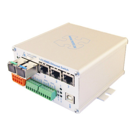
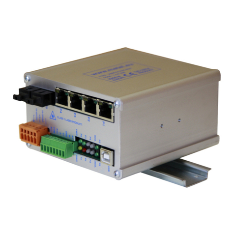
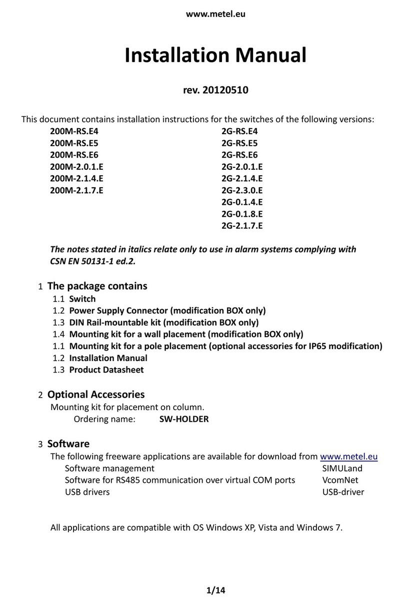
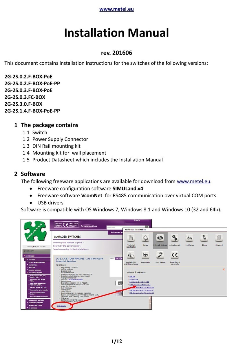
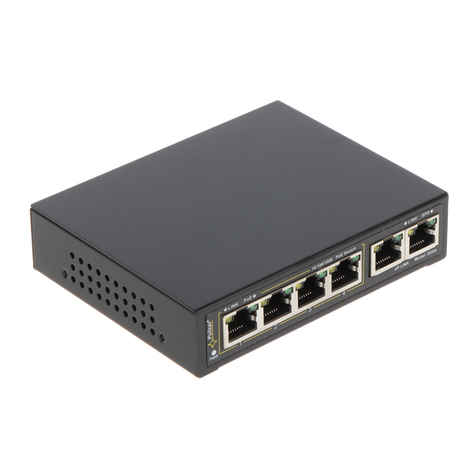
Metel 2G-2.1.4.E-BOX-PoE++ User manual

www.metel.eu 1/10
LAN-RING System PoE++ Managed Switches
2G(200M)-2.1.4.E PoE++
OBJEDNACÍ NÁZEV KÓD NAPÁJENÍ
2G-2.1.4.E-BOX-PoE++ 1-859-226 10-60VDC/10-30VAC**
200M-2.1.4.E-BOX-PoE++ 1-759-226 10-60VDC/10-30VAC**
LAN-RING 2Gbps
GE
IO
IO
IO
RS485
IO
RS485
IO
IO
RS485
IO
RS485
RS485
6x IO
6x IO
6x IO
6x IO
6x IO
RS485
2G-2.1.4.E++ 2G-2.1.4.E++
2G-2.1.4.E++
2G-2.1.4.E++ 2G-2.1.4.E++
2G-2.1.4.E++
2G-2.1.4.E++
EXP-C EXP-C
EXP-C EXP-C
EXP-C
2G-0.1.4.E
2G-0.1.8.E
2G-2.0.1.E
RS485
IO
RS485
IO
RS485
** supply with PoE+ 53-57VDC, without PoE 10-60VDC/10-30VAC
1x MM or SM fiber
Fast Ethernet
LEGEND
others
Gigabit Ethernet
** supply with PoE 48-56VDC, without PoE 10-60VDC/10-30VAC
* holder DIN35-LOCK for mounting to DIN35 included
▪Ring topology LAN-RING
▪Overvoltage protection 1kA on FE ports
▪1x RS485 port with support of:
APOLLO, ASSET, ATS, CIAS, DOMINUS, GALAXY,
HUB-PRO, PERIDECT, ROGER, SATEL-ACCO,
SICURIT-ABSOLUTE, STATION-ONE, Modbus
▪2x digital input
▪1x programmable relay
▪2x MM/SM universal optical ports with WDM
▪1x Gigabit Ethernet
▪3x Fast Ethernet port with PoE support (15.4W)
▪1x Fast Ethernet port with PoE++ support (90W)
▪2 supply inputs
▪IP Watchdog
▪SNMP, SMTP, SNTP, IGMP, UPNP support
▪Support VLAN, 802.1p/q, QoS
▪ Support of logging to SD card
▪Working temperature from –40°C to +70°C
BOX* BOX + DIN35-LOCK*

www.metel.eu 2/10
Installation manual REV:201301
2G(200M)-2.1.4.E PoE++
LAN-RING System PoE++ Managed Switches
Ring topology LAN-RING
LAN-RING is suitable especially for extensive alarm and automation systems. The core of the system are industrial switches
supporting ring topology with fast reconfiguration in 30ms. The swithes are apart from Ethernet port (optics / twisted pair)
equipped with other ports such as RS485, RS422, RS232, digital inputs, relays outputs, TTL inputs/outputs and audio inputs/
outputs (see the table). That enables interconnection of multiple systems (IP CCTV, automation, LAN, ESS, PIDS etc.) using one
optical fiber.
* it is not possible to use both interfaces at the same time
5-year ALL INCLUSIVE warranty
For all LAN-RING system devices we provide 5-year ALL INCLUSIVE warranty including damage caused by excessive voltage (for
detailed specification see “Warranty ALL INCLUSIVE” on our webpages www.metel.eu).
Overvoltage protection 1kA on FE ports
Overvoltage protections of LAN-RING switches guarantee reliable operation even
in outdoor installations. The optimum placement of the switch, devices and cables
connected to the switch is in protection area
of a lightning rod, i.e. ZBO0B zone acc. to IEC 62305-4.
The switches ports are protected in two ways:
- two-level class D protection consisting of lightning
arresters, separating impedances and transils
- fine class D protection consisting of transils
* When connecting switches in outdoor environment we recommend
having all ports with supply feed longer than 10m protected by protections: .
RS485 RS422 RS232 Relays Dig. Inputs TTL IN/OUT Audio IN/OUT
2G-6S.1.16.E 1 - - 1 2 - -
2G-2.1.7.E 1 - - 1 2 - -
2G(200M)-2.1.4.E 1 - - 1 2 - -
2G(200M)-2.0.4.ECA(B) 1 1(A) - 1 2(B) - -
2G-2.3.0.E 1 - - 2 2 - -
2G(200M)-2.0.1.E 1 - - 1 2 - -
200M-EVA(8).E - - - 1 - 2/2 (8/8) 2/2
2G-0.1.8.E - - - - - -
2G(200M)-RS.E RS485* - RS232* 1 (max. 60V/1(0.4)A) 2 -
Backup
segment
Failure
Backup
segment
GE
230VAC
Supply line in ZBOB zone up to 10m over 10m
Fast ethernet ports no no
Gigabit ethernet ports no yes
Supply inputs no yes*
RS485/422/232 ports no yes
Digital inputs no yes
Relay outputs no yes
* we recommend using outdoor supply SU-230/4870H
Switch grounding
SU-230/4870HOVP
OVP –fast ethernet
OVP
OVP
DI
DO
Is it necessary to instal additonal overvoltage protections? Lightning rod
sw
Switch and camera in
protection areaof the
lightning rod
ZBO0B
ZBO0A

www.metel.eu 3/10
Installation manual REV:201301
2G(200M)-2.1.4.E PoE++
LAN-RING System PoE++ Managed Switches
1x RS485 port
The switches are equipped with one RS485 port. This port can be set in three basic modes:
TCP server/client –for direct interconnection with the application on control server,
UPD mode –for interconnection of 2 or more devices with the request of extremely low latency. Typical latency is 3-4ms on
bitrate 9.6kbps.
IO(EXP-C) mode –for connection of up to 15 I/O units EXP-C (6 digital inputs/outputs), temperature sensors, etc.
2x digital input
The switches are equipped with two digital inputs compatible with balanced
loops of all alarm systems. The input state can be:
- Sent via SNMP protocol to integration software (e.g. C4)
- Remapped to relay of other switches or I/O modules.
Everything is adjustable locally via USB or remotely over LAN software SIMULand.
1x programmable relay
The switches are equipped with a programmable relay output which could be activated by e.g.:
- Connection failure over LAN or RS485, interruption of optical ring, etc.
- Opening (closing) of one or more inputs on other switches and I/O modules
- Function IP watchdog that automatically restarts "frozen" devices
- SNMP protocol from integration software (e.g. C4)
Everything is adjustable locally via USB or remotely over LAN software SIMULand.
2x MM / SM universal optical ports with WDM
All optical ports on 2G(200M)-...E series devices can be universally used for both MM and SM fibers in the range of 8/125μm to
62.5/125μm. Optical ports are equipped with integrated wavelength division multiplexer technology (WDM). The optical
ring/connection is then made up of only one SM or MM fiber.
RS485 RS485
RS485
TCP
switch
switch
switch
switch
RS485 RS485
RS485
UDP
switch
switch
switch
switch
IO
RS485
RS485
EXP-C
switch
EXP-C
EXP-C
switch
switch
RS485
EXP-C
polytron 10k
10k
10k
10k
10k
+3.3V
polytron
IN1
IN2
GND
NC
NO
GND
Optical power 2G/200M: –9...–3/–14...–8 dBm 9/125µm
Sensitivity 2G/200M: –22/28 dBm 9/125µm
Optic fibers 1x SM 8(9)/125 - SC connectors µm max. 20 km between components
1x MM 50(62,5)/125 - SC conn. µm 2G/200M: max. 2/5 km between components
Wavelengths PORT 6: Tx: 1310 / Rx: 1490(1550) nm (200M)
PORT 7: Tx: 1490(1550) / Rx: 1310 nm (200M)
Safety WARNING: converters contain laser sources of class 1 according to EN 60825-1-1
Parameter Value Unit Note

www.metel.eu 4/10
Installation manual REV:201301
2G(200M)-2.1.4.E PoE++
LAN-RING System PoE++ Managed Switches
LAN (UTP) Supported formats FE UTP ports: 10BaseT, 100BaseTx
GE UTP ports: 10BaseT, 100BaseTx, 1000BaseTx
Overvoltage protection FE ports: 1000 A 8/20us
GE ports: 30 A 8/20us
Connectors RJ45
Relay output Max. load 62,5VA (30W) / 1A / 60V resistive load
With PoE 48-57 VDC
With PoE++ 53-57 VDC
Power consumption Max. 5 W
Protections Overvoltage / current 100A (8/20µs)
Environment Operational range –40...+70 °C temp. of environment
Storage range –40…+85 °C
Humidity max. 95% non-condensing
Management Local / remote USB / application SIMULand / Win XP. 7 32 and 64bit
Power supply Without PoE 10-60 / 10-30 VDC/AC
Certification TÜV
The producer retains the right to change any technical parameters without previous announcement.
Parameter Value Unit Note
1x Gigabit Ethernet port
The port support standards 10BASE-T, 100BASE-TX, 1000BASE-T incl. functions: Auto-negotiation, Auto MDI/MDI-X, Power-down.
3x Fast Ethernet port with PoE+ (15,4W) support
The port support standards 10BASE-T, 100BASE-TX incl. functions: Auto-negotiation, Auto MDI/MDI-X and Power-down. The
ports also support supplying of terminal devices over Cat-5e cable acc. to IEEE 802.3-af / IEEE 802.3at (max. 15,4W per port).
1x Fast Ethernet port with PoE+ (90W) support
The port support standards 10BASE-T, 100BASE-TX incl. functions: Auto-negotiation, Auto MDI/MDI-X and Power-down. The
ports also support supplying of terminal devices over Cat-5e cable acc. to IEEE 802.3-at / IEEE 802.3at (max. 90W).
2x supply input
The switches are equipped with 2 independent supply inputs.
IP Watchdog
The switches are equipped with integrated IP Watchdog on FE ports. In case of failure they can reset PoE supply, activate relay
output or send a SNMP trap.
Support of SNMP, SMTP, SNTP, IGMP, UPNP
SNMP Protocol for data acquisition and control via LAN.
SMTP Protocol for sending e-mails.
SNTP Protocol for centralized time synchronization.
IGMP Protocol for the management of multicast groups.
UPNP The protocol for the detection of devices connected to the LAN (switches only support the transfer UPNP).
Support of VLAN, 802.1p/q, QoS
The switches support setting of VLAN, priorities and band width independently on all Ethernet ports.
Support of logging to SD card
The switches support logging of important operating data to a SD card.
Technical parameters

www.metel.eu 5/10
Installation manual REV:201301
2G(200M)-2.1.4.E PoE++
LAN-RING System PoE++ Managed Switches
Installation and Setting
1. Mounting
Modification BOX –flat surface or DIN35
2. Connect supply
10-60VDC or 10-30VAC between terminals acc. to the
picture below. The supply is indicated by yellow LED PWR.
Overvoltage protections are grounded via GND terminal.
Connect GND terminal with ground using a cable of min.
1.5mm2 diameter.
3. Connect optic fibers
terminated by SC connector (grinding PC). Optical output
is indicated by green LED of a given port. Blinking
indicates data.
It is necessary to connect optical ports cross-wise,
i.e. port P6 to port P7 etc.
Note: Before closing the optical ring one switch
must be configured as Master (menu "Ring").
4. Connect signal wires
RS485 –connect bus A+ and B-, A+ is positive In the idle
state.
USB - connector for connection of USB A-B cable for local
management over SIMULand application.
RELAY - in alarm state COM and N.O. are closed.
Alarm state is considered in the following situations:
supply failure, communication loss and optic fiber
interruption.
In non-alarm state COM and N.C. are closed.
IN, OUT -digital inputs are activated by closing to GND or
by TTL level (0-0.3V „log 0“ and 2.7V-5V „log 1“).
TTL outputs can be mapped in switch management.
Revision:201301Revision:201301 - Default
Main supply:
No PoE: 10...60VDC 10-30VAC
With PoE: 48...57VDC
With PoE+: 53...57VDC
Redundant supply
No PoE: 10...60VDC
With PoE: 48...57VDC
With PoE+: 53...57VDC
GND (PE)
GND (PE)
GND (PE)
+
+
~ ~
Fast configuration
1. Download and install
application SIMULand.
2. Run application SIMULand
3. From menu „Project/Find devices“ scan avalaible
devices and put it on desktop. (IP adress network card
must be config in the same IP range as the IP address of
the switch)
4. Move the mouse cursor on the device, click on the left
and then the right mouse button. Select the menu
"Configuration / Online configuration" and enter the
password.
5. Basic setting:
menu „IP“ - setting the IP address, subnet mask and
gateway
„Enable answer to ping“ - enable / disable switch to reply
to a ping.
„Enable network management“ - unchecking the items
you will be able to switch only connect via USB.
6. Before closing the optical ring must be in the menu
„Ring“ always one switch is set to „Master".
When use more optical ring you must set every optical
ring another „Ring ID“.

www.metel.eu 6/10
Installation manual REV:201301
2G(200M)-2.1.4.E PoE++
LAN-RING System PoE++ Managed Switches
Activation PoE/PoE++ on Fast Ethernet ports
1. In menu „Ports“ select FE ports FE („P1 –P4“),
where you want to activate PoE supply.
2. Checking the „Enabled" to enable PoE power supply
on the port.
3. On one of the ports „P1 - P4" You can turn
PoE + + by checking the „Poe + + Enabled".
Note: Item „Ignore discovery“ - pernamently turn on
PoE power supply without detection and classification
of PoE end devices.
The setting consists of the following steps:
1. In menu „Bus/Mode“ set the system you are using. If not provided select “RS485”set „Speed“ and „Data bits“. If the system
is provided in the menu no further setting in menu „Bus“ is needed. The switch sets it automatically.
2. In menu „Ethernet“ set receiving and transmitting addresses in range 239.0.0.0 - 239.255.255.255 (multicast).
topology BUS –set the same receiving and transmitting address on all switches.
topology POINT-to-POINT –set the addresses “crosswise”:
Example: Device 1 receiving address - 239.192.168.2, transmitting address 1 - 239.192.168.3
Device 2 receiving address - 239.192.168.3, transmitting address 1 - 239.192.168.2
LAN-RING
Tx 239.192.168.1
Rx 239.192.168.1
Tx 239.192.168.1
Rx 239.192.168.1
Tx 239.192.168.1
Rx 239.192.168.1
Fast Ethernet
LEGEND
RS485
Gigabit
1x MM or SM fiber
Setting of RS485 transmission in UDP mode (multicast)

www.metel.eu 7/10
Installation manual REV:201301
2G(200M)-2.1.4.E PoE++
LAN-RING System PoE++ Managed Switches
LAN-RING
IP: 10.0.1.25
Port: 10485
IP: 10.0.1.27
Port: 10485
IP: 10.0.1.26
Port: 10485
TCP Client
The setting consists of the following steps:
1. In menu „Bus/Mode“ set the system you are using. If not provided select “RS485”set „Speed“ and „Data bits“. If the system
is provided in the menu no further setting in menu „Bus“ is needed. The switch sets it automatically.
2. In menu „Ethernet/TCP Port“ set numbers of TCP ports that will be used by a TCP client to establish communication.
3. Configure the TCP client in a PC with installed application (e.g. integration software).
Setting of RS485 transmission in TCP mode
Fast Ethernet
LEGEND
RS485
Gigabit
1x MM or SM fibre

www.metel.eu 8/10
Installation manual REV:201301
2G(200M)-2.1.4.E PoE++
LAN-RING System PoE++ Managed Switches
input 1 input 2 input 1 input 2
PoE+ managed switches 2G-2.1.4.E
2x FO 2Gbps ♦1x GE ♦4x FE ♦1x RS485/Modbus ♦2x digital input ♦1x relay
CD - connected fiber detection
ACT - activity detection
P7 - optical port 2Gbps LAN-RING
Tx - 1490nm / Rx - 1310nm
P6 - optical port 2Gbps LAN-RING
Tx - 1310nm / Rx - 1490nm
CD - connected fiber detection
ACT - activity detection
P5 - gigabit Ethernet
10/100/1000 BASE-T
overvoltage protection
30A (8/20us)
USB - local management
application SIMULand over USB A-B
cable
P/R - LED POWER / RING
RS485 - LED RS485 TX(R) / RX(G)
RS485
max. 57.6 kbps
overvoltage protection
30A (8/20us)
PoE indication
POx - PoE ON
FAx - PoE fault
P...P4 Ethernet
10/100 BASE-T PoE* ports
LED - DUPLEX/COLLISION
ACT - LED ACTIVITY
overvoltage protection
1000A (8/20us)
LAN-RING
PCPC
GE
IO
RS485
IO
RS485
IO
RS485
GE
GE
4x
PoE+
4x
PoE+
4x
PoE+
! C L A S S 1 L A S E R P R O DU C T !
CD ACT
CD ACT
P7
P6
P5
PO4
PO3
PO2
PO1
P4
FA4
FA3
FA2
FA1
P3
P2
P1
USB
IN 1
IN 2
RELAY
A+
GND
B-
P/R
PoE
RS 485
2G-2.1.4.E
RELAY OUT
62,5VA (30W) / 1A / 60V
(resistive load) current limiter
(polytron)
ORDERING NAME SUPPLY with PoE/PoE++ SUPPLY without PoE TAMPER
2G-2.1.4.E 2G-2.1.4.E
2G-2.1.4.E
2G-2.1.4.E-BOX-PoE++ 48-57/53-57 VDC 48-57/53-57 VDC 10-60 VDC / 10-30 VAC 10-60VDC no
DIGITAL INPUTS
activation by closing to
GND or by TTL level
„log. 0“ 0V-0.8V
„log. 1“2V-5V
overvoltage protection
30A (8/20us)
*In application SIMULand can
select one port for PoE++

www.metel.eu 9/10
Installation manual REV:201301
2G(200M)-2.1.4.E PoE++
LAN-RING System PoE++ Managed Switches
PoE+ managed switches 200M-2.1.4.E
2x FO 200Mbps ♦1x GE ♦4x FE ♦1x RS485/Modbus ♦2x digital input ♦1x relay
input 1 input 2 input 1 input 2
LAN-RING
PCPC
GE
IO
RS485
IO
RS485
IO
RS485
GE
GE
4x
PoE+
4x
PoE+
4x
PoE+
ORDERING NAME SUPPLY with PoE/PoE+ SUPPLY without PoE TAMPER
200M-2.1.4.E 200M-2.1.4.E
200M-2.1.4.E
200M-2.1.4.E-BOX-PoE++ 48-57/53-57 VDC 48-57/53-57 VDC 10-60 VDC / 10-30 VAC 10-60VDC ne
CD - connected fiber detection
ACT - activity detection
P7 - optical port 200Mbps LAN-RING
Tx - 1490nm / Rx - 1310nm
P6 - optical port 200Mbps LAN-RING
Tx - 1310nm / Rx - 1490nm
CD - connected fiber detection
ACT - activity detection
P5 - gigabit Ethernet
10/100/1000 BASE-T
overvoltage protection
30A (8/20us)
USB - local management
application SIMULand over USB A-B
cable
P/R - LED POWER / RING
RS485 - LED RS485 TX(R) / RX(G)
RS485
max. 57.6 kbps
overvoltage protection
30A (8/20us)
PoE indication
POx - PoE ON
FAx - PoE fault
! C L A S S 1 L A S E R P R ODU C T !
CD ACT
CD ACT
P7
P6
P5
PO4
PO3
PO2
PO1
P4
FA4
FA3
FA2
FA1
P3
P2
P1
USB
IN 1
IN 2
RELAY
A+
GND
B-
P/R
PoE
RS 485
200M-2.1.4.E
RELAY OUT
62,5VA (30W) / 1A / 60V (resistive
load) current limiter (polytron)
DIGITAL INPUTS
activation by closing to
GND or by TTL level
„log. 0“ 0V-0.8V
„log. 1“2V-5V
overvoltage protection
30A (8/20us)
P1 - P4 Fast Ethernet
10/100 BASE-T PoE* ports
LED - DUPLEX/COLLISION
ACT - LED ACTIVITY
overvoltage protection 1000A
(8/20us)
*In application SIMULand can
select one port for PoE++

www.metel.eu 10/10
Installation manual REV:201301
2G(200M)-2.1.4.E PoE++
LAN-RING System PoE++ Managed Switches
Size 2G a 200M-2.1.4.E PoE++
This manual suits for next models
3
Table of contents
Other Metel Switch manuals
Popular Switch manuals by other brands
Intelligent network solutions
Intelligent network solutions TSM100-K quick start guide
Rockwell Automation
Rockwell Automation Allen-Bradley Stratix 5800 installation instructions

turck
turck TBIL-M1-16DIP Instructions for use
Hawk
Hawk Gladiator instruction manual

Macrom
Macrom M-AVM6010 quick guide
NETGEAR
NETGEAR ProSafe GS116v2h2 installation guide
