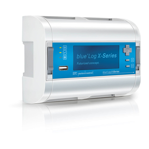
Meteo Control BLUE LOG XM User manual

BLUE’LOG XM / XC
Quick Start Guide
Version 20180827

1
DEVICE OVERVIEW
(1)
LED: Power supply status
(2) LED: Device status
(3) LED: Online status
(4) USB port
( ) Directional pad
(6) OK button
(7) ESC button
(8) Display
(9) DIN top-hat rail latch
(10)
Network socket (RJ4 )
(11)
Interface: RS48 -1
(12)
Bus termination of ⑪
(13)
Bus termination of ⑭
(14)
Interface: RS48 -2
(1 )
Voltage output:
24 V / 00 mA
(16)
Power supply:
24 V
(17)
Digital inputs (4x)
(18)
Interface: CAN
(19)
Bus termination of ⑱
(20)
Reset button
(21)
Digital output / Multi-input
(22)
Side cover left
(23)
Side cover right: Removal for
device expansion

2
Distance between holes: 80
mm
ASSEMBLY ON THE DIN TOP-HAT RAIL
① blue’Log XM / XC
② DIN top-hat rail
③ Open latch (position: down
④ Upper edge of DIN top-hat
rail
⑤ Press the device
⑥ Latch nose extended
⑦ Closed latch (position: up
WALL INSTALLATION
Insert two screws 80 mm apart into the wall. Hang the device on the screws using
the recesses on the rear side. Push the device downward and check to make sure it
is attached correctly.
To remove the device, push it up and pull it off to the front.

3
BLUE’LOG EXPANSION (MX MODULES)
The blue Log base device can be expanded to provide additional interfaces using
various expansion modules (MX modules). For installation information, see the
operating manual for blue Log XM / XC or the instructions for the relevant MX
module at https://www.meteocontrol.com/en/services/downloads/ in the section
“Photovoltaic Monitoring – Products”.
POWER SUPPLY
The current consumption of the blue Log must be restricted by using an energy-
limited circuit. A DC source with limited power may also be used.
The power supply of the blue Log must meet the following requirements:
Device protection
Voltage: 24 V DC | Current: 3.3 A
You will find details of device protection and further connection options in the
operating manual of blue Log XM / XC.
ASSIGNMENT OF CONNECTIONS
The specific connection parameters of the devices to be installed (e.g. inverters,
energy meter, sensors) can be found in the “Compatibility list – blue Log XM / XC”
and the manufacturer s instructions for the relevant device.
Compatibility list https://www.meteocontrol.com/service/downloads/

4
STATUS LEDS
The meaning of the LEDs on the front of the blue Log:
Symbol LED Meaning
Green: blue Log is supplied with power
Off: No power supply
Green: System loaded successfully, normal
operation
Orange: System booting, boot phase
Red: System error
Green: Connected to VCOM
Orange: Establishing connection to VCOM
Red: No connection to VCOM
BLUE’LOG CONFIGURATION – NETWORK
The blue Log is configured via your web browser (e.g. Chrome, Firefox). In order to
configure it, you must first configure the network and set up user access.
Network configuration
The Ethernet connection of the blue Log must be connected to a LAN network (e.g.
LAN interface PC, router, switch)
The current IP address of the blue Log is shown on the display s start screen.
Network:
• With DHCP server: IP address assigned by DHCP server
• Without DHCP server: IP address generated randomly by the
blue Log
(range: 169.254.XXX.XXX)
To adjust your network parameters (DHCP or static), navigate to the network settings
by using the directional pad and the buttons.

5
Display
BLUE’LOG CONFIGURATION – WEB INTERFACE
Browser registration
To connect to your blue’Log, enter the blue’Log IP address in the address bar of your
Internet browser.
As an alternative, you may enter the blue’Log’s host name*.
Router – network support:
• DNS, Netbios: http://blue-xnnnnnnnn
• No DNS, Netbios: http://blue-xnnnnnnnn.local
n = last eight digits of the hardware number
*The host name can be changed via the web interface in the “System – Ethernet”
menu.
Setting up user access
You need to set up user access when logging on for the first time. Please give a user
name, password, display PIN and e-mail address.
User data can be changed and other users set up via the web interface in the
“System – Users” menu.

6
Welcome to the Setup Wizard
At the first login on the blue Log you configure the “Security and privacy settings”
and in addition to that you have the option to choose the Setup Wizard which will
then hep you set up the device step by step.
The wizard can be closed and launched again at any time.
Support Acce
The “Support Access” is deactivated in the factory settings. If you don t activate the
access, meteocontrol is not able to connect to the device in case of service.
You can change the setting at any time in the menu “System – User”.
Firmware update and time zone
When using the device for the first time, you should check whether
• a new firmware update is available
• the correct time zone is set.
The wizard will automatically guide you through these settings. If you are not using
the wizard, navigate as follows
1. Firmware update “System – Update*” menu
2. Time zone “System – Date & Time” menu
*When the firmware is updated, the “driver package” will automatically be updated
at the same time.

7
CONNECTION TO VCOM – REGISTRATION
In order to establish a connection to VCOM, you first need to set up a system in VCOM.
After that, you can register in two ways:
1. Via the blue Log web interface
2. Via VCOM
blue’Log web interface
In the “PV System – VCOM” menu, you need to give a system key (e.g. WTTRY), a
VCOM user name and a password and then click on “Registration”.
You can set the transfer interval to the desired frequency. The time indicates how
often the data in VCOM will be updated.
VCOM
Open the “Register Data Logger” tab in the “System Configuration – blue Log
X series – Administration” menu.
Add the blue Log, giving the blue Log hardware number (HW No.), the blue Log user
name and the password.
Note regarding data protection (GDPR)
At this point, we would like to inform you what data we collect when you configure and use the blue’Log.
•
User name, password, e-mail address => hese data are only stored locally on the logger’s SD card
•
E-mail addresses => he e-mail addresses entered in the user administration and the alarm configuration can be
viewed by any user and are transferred to VCOM for information purposes.
Further information regarding data protection at meteocontrol: https://www.meteocontrol.com/en/contact/data-privacy/
Further information:
www.meteocontrol.com
Text and
illustrations represent state-of-the-art technology at the time of printing • Subject to technical modifications • We assume no
liability for printing errors. Item number 83 09
3 • Version 01808 7
This manual suits for next models
1
Table of contents
Other Meteo Control Other manuals
