HEIDENHAIN ND 510 User manual

Numeric keypad
and decimal point
•Sign
• Change parameter
Confirm
entry values
•Call operating
parameters
• Page forward in
parameter list
Datum setting
function
Status indicators
•Select datum
• Page backward in
parameter list
Indicator Meaning
REF Reference mark was crossed over – datum points are now stored
in non-volatile memory.
Blinking: Waiting for reference mark to be crossed over.
in. Position values displayed in inches.
1 / 2 Datum point 1 / Datum point 2 currently active.
SCL Scaling factor active.
Define workpiece edge as datum.
Blinking: Waiting for operator to confirm selection.
Define centerline between two workpiece edges as datum.
Blinking: Waiting for operator to confirm selection.
•Clear entry
• CL plus two-digit number:
select parameter
• Clear parameter entry
•Select coordinate axis
(Z-axis with ND 550 only)
• Select axis-based operating parameters
Actual value and input display
(7-segment LED,
8 decades and sign)
Downwards: X-axis, Y-axis,
ND 550 only: Z-axis
MOD
0
Y
X
HEIDENHAIN
3
6
5
4
2
1
ENT
8
79
Z
REF 12
CL
1
2
SPEC
FCT
SCL
in.
←←
←←
←
→→
→→
→
Working with the digital readouts
ND 510 ND 550
HEIDENHAIN
←←
←←
←

Touching the workpiece
The ND 510 and ND 550 digital readouts accept HEIDENHAIN linear encoders with
sinusoidal output signals.
These linear encoders have one or more reference marks, preferably of the distance-
coded
type. When a reference mark is crossed over, a signal is generated which
identifies that position as a reference point.
After switch-on, simply crossing over the reference mark restores the relationship
between axis positions and display values last defined by datum setting.
With distance-coded reference marks, a maximum traverse of only 20 mm is suffi-
cient to re-establish the relationship between axis positions and display values after
switch-on.
Switch-On
Turn on the power
➤The power switch is located on the rear panel.
The display shows and REF blinks.
Turn on reference mark evaluation
➤Press the ENT key.
The display shows the value last assigned to the reference mark position, the REF
indicator glows and the decimal point blinks.
Cross over the reference mark in each axis
➤Move the axes one after the other until the display becomes active and the
decimal point glows.
The display unit is now ready for operation.
If you do not
wish reference mark evaluation, press CL instead of ENT.
Setting the Datum
The datum setting procedure assigns a display value to a specific axis position.
Two separate datum points can be defined.
You can switch from one datum to the other
at the touch of a key.
Use datum 2 if you want to display
incremental values.
➤Select the datum.
➤Select the coordinate axis
in which the tool moves,
for example the X-axis.
➤Touch the workpiece with the tool.
➤Enter the position of the tool center
with the numeric keypad, for example X = –5 [mm]. The minus sign can only be
entered when at least one digit is shown in the display.
➤Press ENT.
The display unit stores the value for this tool position.
Follow the above procedure for other axes.
Y
X
Z

Datum Setting Functions
The special functions which your display unit is capable of allow you to define a
workpiece edge or the centerline between two workpiece edges as the datum. With
the SPEC FCT feature, the display unit takes into account the tool diameter you
entered in operating parameter P25.
Workpiece edge as datum
➤Select the datum.
➤Press the SPEC FCT key once.
The indicator "Workpiece edge as datum"
starts blinking.
➤Press ENT.
The indicator glows.
➤Select the coordinate axis in which the
tool moves.
The selected coordinate axis glows more brightly.
➤Touch the workpiece with the tool.
➤Press ENT.
The display shows the current position of the edge.
➤Enter the new coordinate value for the workpiece edge that was touched.
➤Press ENT.
The display unit sets the workpiece edge to the new value and displays the
position of the tool center based on the new datum.
This function ends automatically.
Centerline between two workpiece edges as datum
➤Select the datum.
➤Press the SPEC FCT key twice.
The indicator "Centerline as datum"
starts blinking.
➤Press ENT.
The indicator glows.
➤Select the coordinate axis in which the
tool moves.
The selected coordinate axis glows more brightly.
➤Touch the first workpiece edge with the tool.
➤Press ENT.
The decimal point in the display blinks.
➤Touch the second workpiece edge with the tool.
➤Press ENT.
The display shows the current position of the centerline.
➤Enter the new coordinate value for the centerline between the two touched
workpiece edges.
➤Press ENT.
The display unit sets the centerline to the new value and displays the position
of the tool center based on the new datum.
This function ends automatically.
Aborting the datum setting functions
➤To abort when the indicator for the function is blinking:
Press CL.
➤To abort when the indicator for the function is glowing steadily:
Press SPEC FCT.
Y
X
Z
X?
Workpiece edge as datum
Y
X
Z
X?
Centerline as datum

Non-linear Error Compensation
To work with the non-linear error compensation it is necessary to
•activate the function via the operating parameter P40.
•traverse the reference marks after switching on.
•enter the compensation values in the table.
For every axis compensation values can be entered over 16 compensation points.
To determine the compensation values with a comparator system from
HEIDENHAIN, such as VM 101, you must select the REF display.
Selecting the Compensation Value Table
➤Select the operating parameter P00 and enter the code number 105 296. Use
the following keys for the entries:
Key Function
MOD Save input value and select next input parameter.
1 / 2 Save input value and select preceding input value.
SPEC FCT Select REF display.
ENT •Save entry.
•Exit compensation value table.
CL •Delete entry.
•Delete all compensation values.
➤Enter the parameters and compensation values as follows:
Display Entry
Enter the axis to be compensated, e.g. X.
Enter the axis causing the error, e.g. X, i.e. X = F(X).
Enter the datum on the axis causing the error.
Enter the distance of the compensation points on the error-
causing axis, e.g. 14 (= 214 µm = 16.384 mm).
Minimum input value: 10 (= 1.024 mm)
Maximum input value: 23 (= 8388.608 mm)
Select compensation point No. 1. The compensation point
number can be seen while pressing the MOD key. After letting
go of the MOD key the coordinates of the selected compensation
point can be seen in the upper line. Enter the compensation value
in the lower line.
Enter all following compensation points.
Delete all compensation values:
Display Entry
Press key CL.
Press key ENT. Compensation values are deleted.

Working with Scaling Factors
The ND 510 and the ND 550 can display the axis traverse lengthened or shortened by
a scaling factor. You enter a scaling factor separately for each axis in the user
parameter P12, then activate the scaling factor function with the user parameter
P11. SCL is highlighted.
Error Messages
Message Cause and effect
Traverse distance with datum setting function (SPEC FCT) is
too short
Incorrect input value
Input frequency too high for encoder input
(will occur for example when traverse speed too high)
Internal counter overflow
Error while crossing over reference marks
To clear the error message: Switch of the display unit.
Should any of these error codes recur, contact your
HEIDENHAIN service agency.
Compensation values for nonlinear axis error compensation have
been erased
Datums have been erased
Erase the operating parameters
If all decimal points light up, the measured value is too large or too small.
Set a new datum.
To clear error message :
When you have removed the cause of the error,
➤press CL.

Operating Parameters
User Parameters
User parameters are operating parameters that can be changed without entering the
codes: P00 to P25
Axis assignment
Parameters which are entered separately for each axis have axis codes:
"1" signifies the X-axis, "2" the Y-axis, and (with the ND 550) "3" the Z-axis.
A point separates the axis code from the parameter number.
In the operating parameter list, these parameters are set off with a superscript "A",
the parameter for the X-axis (e.g. ) is in the list.
You select axis-specific operating parameters with the yellow arrow keys.
To call the operating parameter list:
➤Press MOD.
To go directly to a certain operating parameter:
➤Press and hold CL, then press the first digit of the parameter number.
➤Release both keys and enter the second digit of the parameter number.
Protected Operating Parameters
In order to change protected operating parameters, the code number 95 148 must be
entered via P00 Code: They remain accessible until the position display is switched
off.
To page through the operating parameter list:
➤Page forward: press MOD.
➤Page backward: press the 1 / 2 key.
Any changes are automatically activated when you resume paging.
To change a parameter setting:
➤Change the value with the minus key, or
➤Enter the desired value directly, e.g. for P25.
To correct an entry:
➤Press CL.
To exit the operating parameters:
➤Press ENT.
This activates all changes made.
Operating Parameter List
Parameter Meaning Function / Effect Setting
Code Number 95148: protected operating parameter
105296: select compensation value table
Unit of Display in mm
measurement Display in Zoll
Radius-/diameter Radius
display
ADiameter
Scaling factor Scaling factor on
Scaling
Scaling factor off
Scaling factor AEnter value for each axis separately
Tool diameter Enter tool diameter
Tool

Model
Signal
period [µm]
Reference
marks
P43
Display step
(unit: P01)
mm inches
Subdi-
vision
P32
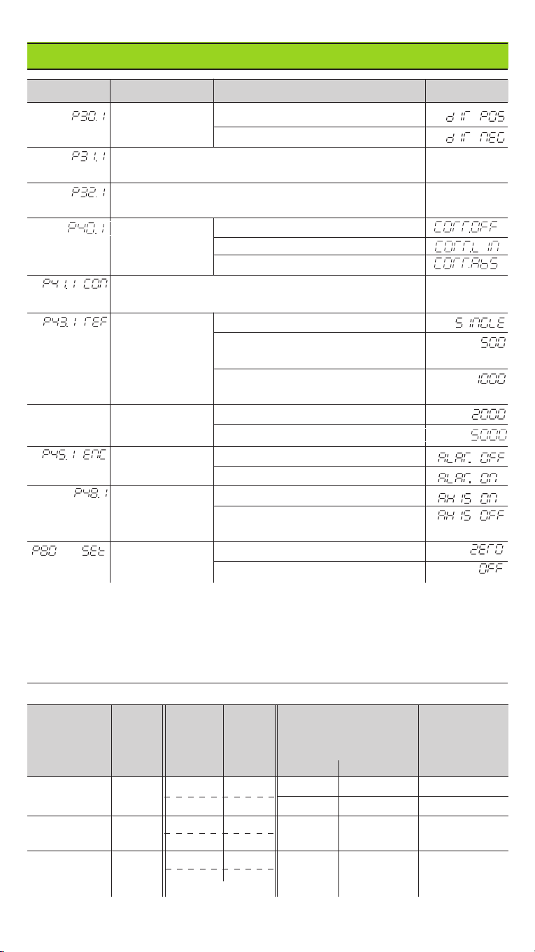
Operating Parameter List – cont'd.
Parameter Meaning Function / Effect Setting
Counting Normal
(Direction: Positive)
direction AInverse
(Direction: Negative)
Signal period of encoder A
(
Period
:) 2, 4, 10, 20, 40, 100, 200
Subdivision of the encoder signals A
(
Subdivision
:) 4, 2, 1, 0.8, 0.5, 0.4, 0.2, 0.1
Select Error compensation not active
error Linear error compensation active
compensation Non-linear error compensation active
Linear error compensation1) A
Compensation
–99 999 < P41 < + 99 999 [µm/m]
Reference One reference mark
marks ADistance-coded with 500 •SP
(SP = signal period)
Distance-coded with 1000 •GP
(e.g. for LS 303 C / LS 603 C)
Distance-coded with 2000 •SP
Distance-coded with 5000 •SP
Encoder Monitoring off
(Alarm Off)
Encoder
monitoring AMonitoring on
(Alarm On)
Axis display ADisplay measured position
(
Axis
) Do not display measured position /
no encoder
Function of Resets display to zero
CL key Does not reset display to zero
1) Calculate the entry value for P41
Example: Displayed measuring length La= 620.000 mm
Actual length (determined with, for example, the VM 101 comparator
system from HEIDENHAIN) Lt= 619.876 mm
Length difference ∆L = Lt–La= –124 µm
Compens. factor k: k = ∆L / La= –124 µm / 0.62 m = –200 [µm/m]
Parameter Settings for HEIDENHAIN Linear Encoders
LS 303 20 one single 0.005 0.000 2 4
LS 603 dist.c. 1 000 0.01 0.000 5 2
LB 302 40 one single 0.01 0.000 5 4
LIDA 10x dist.c. 2 000
LB 3xx 100 one single 0.025 0.001 4
dist.c. 1 000 0.05 0.002 2
0.1 0.005 1
Example: Linear encoder with signal period s = 20 µm
Desired display step a = 0.005 mm
Subdivision P32 ==
==
= 0.001 ••
••
•s / a = 4

Rear Panel
Ground terminal
Power switch
Inputs for HEIDENHAIN linear encoders
(ND 510: 2, ND 550: 3)
with sinusoidal output signals
(7µApp to 16 µApp),
Connecting cable max. 20 m (66 ft),
Input frequency max. 50 kHz with
6 m/20 ft cable (35 kHz with 10 m/32.8 ft,
20 kHz with 20 m/66 ft)
X2 X1
X3
Interfaces X1, X2 and X3 comply with the recommendations in EN 50 178
for separation from line power.
281 615-23 ·SW 246 119 02 ·10 ·6/99 ·H ·Printed in Germany ·Subject to change without notice
56±0.2
2.204±.008"
93+2
3.66+.08"
29+0.5
1.14+.02"
20
.79"
0
21±0.2
1±.008"
209±0.2
8.228±.008"
230±0.2
9.055±.008"
92
3.622"
M4
43.3
1.704"
Installation
You can mount the display unit on a surface
using M4 screws, or on a tilting base from
HEIDENHAIN (Id.-Nr. 281 619 01).
Danger of electrical shock!
Unplug the power cable before opening the housing.
Connect a protective ground. This connection should never be interrupted.
Danger to internal components!
Do not engage or disengage any connections while the unit is under power.
Use only original replacement fuses.
Power Supply and Connection
Primary-clocked power supply.
Voltage range 100 V to 240 V (–15% to +10 %) Frequency 48 Hz to 62 Hz
Power consumption ND510: 9 W, ND550: 12 W Line fuse F 1 A (in unit)
Minimum cross-section of power cable: 0.75 mm2
To increase the noise immunity, connect the ground terminal on the rear panel
to the central ground point of the machine. (Minimum cross-section 6 mm2)
Ambient Conditions
Temperature range Operation: 0°C to +45°C (32°F to 113°F)
Storage: –30°C to +70°C (–32°F to 158°F)
Rel. humidity Annual average: < 75%; maximum: < 90%
Weight 2.3 kg
DR. JOHANNES HEIDENHAIN GmbH
Dr.-Johannes-Heidenhain-Straße 5
D-83301 Traunreut, Deutschland
(0
86
69) 31-0 .56 831
(0
86
69) 50
61
FAX
FAX
Service (0
86
69) 31-12
72
TNC-Service (0
86
69) 31-14
46
(0
86
69) 98
99
This manual suits for next models
1
Table of contents
Other HEIDENHAIN Other manuals
Popular Other manuals by other brands

AxleTech
AxleTech 5000 Series Maintenance manual

Meinberg
Meinberg LANTIME M300/GPS/2LNE/RPS Technical reference

AXXIOM Manufacturing, Inc.
AXXIOM Manufacturing, Inc. SCHMIDT 0.9 Cu. Ft Operation and maintenance manual

Elatec
Elatec TWN4 CONFIG PROGRAMMER quick start guide

HNE
HNE MFU 50-150 user manual

Nady Audio
Nady Audio MPM 8175 owner's manual