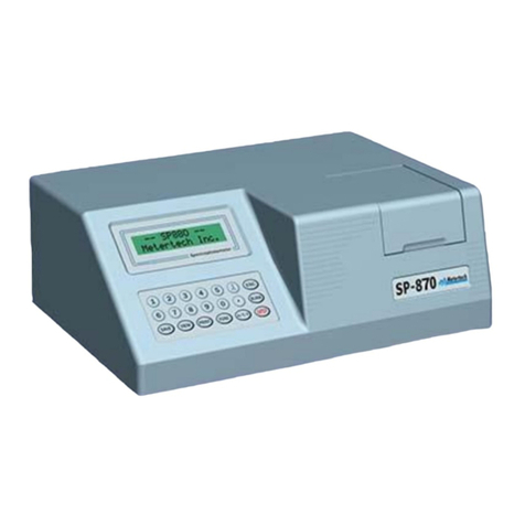
Metertech SP-8001 Quick start guide

Provide
Accurate
Results
Operational Manual
UV/Visible Spectrophotometer
SP-8001
Metertech Inc.
Version 1.2

Metertech
Inc.
provides
this
publication
“as
is”
without
warranty
of
any
kind,
either
express
or
implied,
including, but not limited to the implied warranties of merchantability or fitness for aparticular purpose.
All
rights
are
reserved,
including
those
to
reproduce
this
publication
or
parts
thereof
in
any
form
without
permission in writing from Metertech Inc.
Information in this publication is subject to change without notice and does not represent acommitment on
the part of the vender.
Any
errors
or
omissions
which
may
have
occurred
in
this
publication
despite
the
utmost
care
taken
in
its
production will be corrected as soon as possible, but not necessarily immediately upon detection.
Copyright© Metertech Inc. 1999
Metertech Inc. ‧63-2 Cheng Gong Rd. Sec. 1‧Nangang, Taipei, Taiwan, R.O.C.
E-Mail: info@metertech-inc.com ‧Web Site: www.metertech-inc.com
Tel.: 886-2-2783-2854 ‧Fax.: 886-2-2783-1764

Metertech
Inc.
Contents
2
Chapter
1
Introduction
--------------------
4
§1-1
Specification
--------------------
4
§1-2
Safety Notes
--------------------
5
Chapter
2
Installation
--------------------
6
§2-1
Unpacking
--------------------
6
§2-2
Installation
--------------------
7
Chapter
3
General
--------------------
8
§3-1
User Interface
--------------------
8
§3-2
General Function Description
--------------------
10
§3-3
Initialization
--------------------
12
Chapter
4
System
setup
--------------------
14
§4-1
System Setup Menu
--------------------
14
Chapter
5
Photometric
--------------------
19
§5-1
Photometric Parameter Setup
--------------------
19
§5-2
Photometric Function Structure
--------------------
20
§5-3
Basic Photometric Measurement
--------------------
20
Chapter
6
Spectrum
--------------------
24
§6-1
Spectrum Parameter Setup
--------------------
24
§6-2
Spectrum Function Structure
--------------------
25
§6-3
Basic Spectrum Measurement
--------------------
26
Chapter
7
Timescan
--------------------
31
§7-1
TimeScan Parameter Setup
--------------------
31
§7-2
TimeScan Function Structure
--------------------
32
§7-3
Basic TimeScan Measurement
--------------------
33
Chapter
8
Kinetic
--------------------
35
§8-1
Kinetic Parameter Setup
--------------------
36
§8-2
Kinetic Function Structure
--------------------
37
§8-3
Basic Kinetic Measurement
--------------------
38
Chapter
9
Quantitative
--------------------
40
§9-1
Quantitative Parameter Setup
--------------------
40
§9-2
Quantitative Function Structure
--------------------
41
§9-3
Basic Quantitative Measurement
--------------------
42
Chapter
10
Accessories
--------------------
45
§10-1 Multi-Cell Holder
--------------------
45
§10-2 Sipper
--------------------
47
Chapter
11
Maintenance
--------------------
49
§11-1 Routine Maintenance
--------------------
49
§11-2 Replacement of Lamps
--------------------
50
Appendix
A
Thermal
Controller
Operation
Instruction
--------------------
52
Appendix
B
Sipper
Operation
Instruction
--------------------
54
Appendix
C
Setting
of
USB
Serial
Port
--------------------
57

Metertech
Inc.
3

Metertech
Inc.
Chapter
1
Introduction
The
SP-8001 UV-VIS
Spectrophotometer is
an instrument
designed
and
manufactured
by Metertech
Inc. It
can
meet
the
wide-ranging
needs
of
prospective
users. The
main
unit
features
fundamental
photometric
functions
that
are
ready
expandable
using
various
application
software
packages
and
attachments
for
enhanced
convenience
and
productivity. It
is
designed
to
be
user-friendly
and
require
as
little
engineering
knowledge as possible to adopt in users’ application.
In
order
to
obtain
maximum
performance
and
trouble-free
operation
with
the
SP-8001,
It
is
recommended
that you carefully read this manual before using the SP-8001, and thereafter keep it close at hand for future
reference.
§1-1
Specifications
Wavelength 190-1100nm
Bandwidth <2nm
Wavelength accuracy +/-0.5nm
Monochromator Split Beam (Internal double beam design)
Wavelength repeatability +/-0.2nm
Photometric range -0.3000-4.5000A
0.01-300 %T
0.0000-44995C
Photometric accuracy +/-0.005Abs at 1.000Abs by NIST SRM930e
Stability drifting <0.0003Abs/hr at 500nm after 1hour warm-up
Baseline flatness +/-0.001Abs (at 210-1000nm)
Stray light <0.05% at 340nm &220nm by NIST SRM2031
Light source deuterium lamp (UV range) &halogen lamp (Vis range)
Source lamp change automatic
Detector Silicon photodiodes
Wavelength scanning speed 100-3500nm/min (user-programmable)
Path-length variable at 10-100 mm
Display backlight LCD –adjustable contrast
Interface serial ¶llel
Power/fuse AC input: 100/120/220/240V 50/60Hz,
Fuse: T2A for 220/240V, T4A for 100/120V
Dimension 506(W)X430(D)X220(H)mm
Weight 18kgs
Ambient temp/humidity room temperature 15-35℃,humidity <80%
Specifications subject to change without notice.
4

Metertech
Inc.
§1-2
Safety
Notes
Although
this
SP-8001
UV-VIS
Spectrophotometer
is
user
friendly,
the
instrument
and
its
accessories
described
in
this
manual
are
designed
to
be
used
by
properly
trained
persons
only. READ
THIS
SECTION
CAREFULLY BEFORE INSTALLING AND USING THE INSTRUMENT AND ITS ACCESSORIES.
Adjustment,
maintenance,
and
repair
of
equipment
must
be
carried
out
only
by
qualified
persons
who
are
aware
of
possible
hazards
involved. Wherever
indicated
in
this
manual,
certain
maintenance
may
be carried out by users, who must be fully understand and apply the following safety precautions.
For the correct and safe use of this instrument and its accessories it is essential that both operating and
servicing
persons
follow
generally
accepted
safety
procedures
in
addition
to
the
safety
precautions
specified in this manual.
Some of the chemicals used in spectrophotometer are corrosive, and/or flammable and samples may be
radioactive,
toxic
or
potentially
infective. Care
should
be
taken
to
follow
the
normal
laboratory
procedures for handling chemicals.
Only
the
persons
who
have
been
trained
to
avoid
the
risk
of
electric
shock
are
qualified
to
remove
the
instrument
covers
and
accessories. The
mains
electricity
supply
to
the
instrument
must
be
disconnected
at
the
mains
supply
connector
and
at
least
three
minutes
allowed
for
capacitors
to
discharge.
The
UV
radiation
from
a
deuterium
lamp
can
be
harmful
to
the
skin
and
eyes. Always
view
the
lamp
through protective glasses that will absorb the UV radiation and avoid looking directly at the deuterium
arc. Do not expose the skin to direct or reflected UV radiation.
Whenever
it
is
likely
that
safety
protection
has
been
impaired,
the
instrument
and/or
accessories
must
be
made
inoperative
and
secured
against
any
unintended
operation. The
matter
should
then
be
referred to appropriate service authority.
5

Metertech
Inc.
Chapter
2
Installation
BEFORE
installation
please
read
safety
notes
in
previous
page
carefully. Failing
to
abide
by
the
regulations
may cause damages to the instrument and may obtain incorrect results.
§2-1
Unpacking
The SP-8001 (Figure 2.1 and Figure 2.2) should be delivered with intact packaging that contains one carton
with
items
listed
in
the
packing
list. Unpack
the
carton
and
inspect
carefully. If
any
part
is
damaged
or
missing, contact your local dealer immediately.
lamp compartment sample compartment
Figure 2.1 Top view of the SP-8001
Figure 2.2 Back panel of the SP-8001
Save
the
carton
with
packing
materials
in
a
proper
place
in
case
that
the
instrument
may
need
to
be
repacked or to be returned for service.
6
110/220V slide
power switch
fan
power receptacle
printer port
RS-232
port
LCD contrast adjuster

Metertech
Inc.
§2-2
Installation
Before the first installation, please inspect carefully whether any damages or suspicious
defects you may be
aware
of. Do
the
followings
before
turn
on
the
instrument. Contact
your
local
agent
for
help
if
encountering any difficulties during installation and operation.
A. Always
place
the
instrument
on
a
stable
and
vibration-free
table. Allow
two
inches
behind
the
rear
panel
of
the
instrument
for
air
circulation
and
power
cord,
and
protect
the
instrument
from
being
located:
◆in direct sunlight
◆in drought from window, air conditioner or heater
◆near copy machine
◆near refrigerator or oven
◆near ultrasonic cleaner
◆near X-ray equipment
◆near centrifuge
B. Check
and
set
the
voltage. The
SP-8001
can
be
performed
with
selective
power
supply
at
110 or
220 Vac
50/60Hz
from
a
properly
wired
and
grounded
single
phase
power
outlet. Check
the voltage shown
at 110/220V slide above power receptacle on rear panel. If it is not the desired, use flat screw driver to move
the slide left or right to obtain the correct voltage.
C. The room temperature of operating site should be between 15 -30℃,and humidity less than 80%.
D. Install all desired accessories and connect necessary wires and tubes properly.
E. Plug the power cord into the instrument inlet and to an appropriate wall outlet.
F. Now
the
system
is
ready
for
performance. Turn
power
on
and
refer
details
of
operation
to
specific
sections.
7

Metertech
Inc.
Chapter
3
General
The
SP-8001
is
designed
to
be
a
self-contained
instrument
and
can
work
as
a
standalone
machine
or
can
work with other peripherals together.
The
SP-8001
has
one
membrane-type
keyboard
and
a
320X240
LCD
display
as
the
user
interface. User
may key in data through the keyboard and proper messages will show on the display. Alamp compartment
facilitates
a
tungsten
halogen
lamp
and
a
deuterium
lamp
that
users
are
allowed
to
replace
those
lamps
whenever
needed. READ
SAFETY
NOTES
in
section
§1-2
carefully
and
instructions
in
section
§11-2
before
changing
lamps. A
sample
compartment
is
the
area
for
users
manipulating
their
samples. Also
it
allows
users to install proper accessories for specific operations.
§3-1
User
Interface
The
SP-8001
keyboard
with
LCD
display
module
is
shown
in
Figure
3.1.
Operations
of
those
keys
are
designed
to
be
user
friendly. In
most
of
cases,
users
press
keys
according
to
instructions
shown
in
the
corresponding screens. Otherwise, refer to specific sections of different operation modes for more details.
Figure 3.1 Keyboard with LCD display module
For operations with optional accessories, refer to proper sections in Chapter 10.
General explanation of keys is given below:
Function keys Selecting and performing supporting functions shown in the screens.
Numerical keys For entering numbers, minus, and decimal point
For entering desired wavelength.
CLEAR To clean up unwanted input digits in the entry field.
ESC To quit the current screen and go back to the previous screen, or to quit from the
current process, or to go back to upper level of function key screen.
QUICK RUN To
pop
up
a
Parameter
File
List
(Figure
3.2)
for
users
to
select
operation
settings
8

AUTO ZERO To perform blank correction when needed. It sets the photometric value to 0ABS
Figure 3.2 Quick Run Parameter File List screen
Metertech
Inc.
stored
in
memory. In
this
file
list,
users
can
view
all
parameter
settings
in
different
operation
modes
that
is
distinguished
by
the
first
2
letters
in
the
first
column.
For
example,
PH
represents
for
“Photometric”
mode.
Filenames
are
shown in the second column, while the corresponding time in the third column.
READ To start measuring process according to the current settings.
(100%T) after AUTO ZERO being pressed.
ENTER To confirm selections or entries of fields or parameters.
Arrow keys To
move
the
cursor
between
entry
fields
or
parameters.
Left/right
arrow
keys are also used for switching Yes/No as instructed.
CELL ∧To move sample holder one position up as needed.
CELL To move sample holder one position down as needed.
9
12:00:00
QUICK
RUN
500.0nm
0.000A
Parameter
file
list
--------------------------------------
No
Name
Time
PH-01
ART01
07/01/99
10:12:32
PH-02
PH-03
PH-04
SP-05
HOLMIUM
07/12/99
09:30:12
SP-06
SP-07
SP-08
TS-09
LIGHT01
06/24/99
13:22:43
TS-10
LIGHT02
06/25/99
15:32:33
TS-11
TS-12
KI-13
GOT01
03/21/99
16:37:21
KI-14
KI-15
KI-16
Press
UP
DOWN
key
to
select...

Save Param For saving acurrent settings into memory. Filename is entered
Figure 3.3 Parameter file list in photometric mode
Metertech
Inc.
§3-2
General
Function
Description
Functions
being
used
in
the
SP-8001
are
listed
in
the
corresponding
modes
and
are
shown
in
structured
maps. For those functions being widely used in most of the modes will be described below.
Load Param For loading existing parameter settings stored in memory. When this
function is pressed, aparameter file list screen (Figure 3.3) shows up
and
users
can
choose
from
the
list
by
using
arrow
keys
and
followed
by
an
ENTER
key.
Only
the
mode-relevant
parameter
setting
files
will appear when function Load Param is pressed.
through
a
4
by
9
array-type
table
(Figure
3.4). By
using
up/down
arrow
keys
for
choosing
rows
and
then
numerical
keys
for
choosing
column,
the
desired
alphabet
or
number
will
be
picked
up. 10
alpha-numerical
keys
are
the
maximum
for
a
filename.
Using
left
arrow
key
to
delete
the
input.
An
ENTER
key
will
close
the
input
procedure
and
the
Parameter
File
List
screen
will
show
up.
Using
up/down
arrow
keys
to
choose
a
place
for
the
filename
and
followed
by
an
ENTER
key
will
complete
the
Save
Param
procedure. A
time
tag
will
be
automatically
attached
to
the
saved
filename. Press
function Load Param and you may see what has just been done.
Print Data To print data or graph from the current screen.
Sample Control To be functioning only when certain accessory being used.
10
12:00:00
PHOTOMETRIC
500.0nm
0.000A
Parameter
file
list
--------------------------------------
No
Name
Time
01
ART01
07/01/99
10:12:32
02
03
04
05
06
07
08
09
10
11
12
13
14
15
Press
UP
DOWN
key
to
select...

Figure 3.4 Filename input screen
Metertech
Inc.
Next Screen Accept
the
current
settings
and
switch
into
the
measuring
display
screen. Once
get
the
sample(s)
ready,
press
READ
for
proceeding
the
measurement
according
to
the
setup. Sometimes,
it
is
used
for
tracing
back
to
the
previous
level
of
functions
or
for
showing
the
previous graph on the screen.
Prev Screen Leave the current display screen and switch back to aprevious display
screen.
Manipulate For
further
manipulation
of
current
data
either
from
new
measurement or from existing data files.
Clear Graph To
clean
up
the
current
screen.
This
will
result
in
loss
of
data
in
previous
measurement. Only
those
data
for
the
most
current
measurement
can
be
rebuilt
with
function
Original
under
function
Manipulate.
Load Data To
load
data
with
determined
parameter
setup
from
the
associated
Data File List.
Save Data To
save
the
data
of
current
measurement
or
to
save
the
data
of
chosen
point in
function
Show Track. This
will
also save
the settings
of
parameters
in
that
measurement. Message
“No
data
present
…”
will show if there is no data in the screen.
11
12:00:00
500.0nm
0.000A
1
2
3
4
5
6
7
8
9
>>>
File
Name:ART
Press
UP
DOWN
key
to
select...
A
B
C
D
E
F
G
H
I
J
K
L
M
N
O
P
Q
R
S
T
U
V
W
X
Y
Z
0
1
2
3
4
5
6
7
8
9

Figure 3.6 System Main Menu screen
Metertech
Inc.
§3-3
Initialization
Turn
on
the
power
of
the
SP-8001,
a
start-up
screen
(Figure
3.5)
shows
up
and
the
initialization
of
system
will
be
automatically
done. The
version
of
software
coming
up
with
the
instrument
is
also
shown
in
the
start-up screen. User-installed accessory will be automatically detected during the initialization.
12:00:00
0.0nm
0.000A
Metertech
Metertech
Inc.
SP-8001
UV/VIS
SPECTROPHOTOMETER
All
rights
reserved.
Version
1.3
Detect
Accessory...Single-Cell
Initial
System.....
Figure 3.5 Start-up screen
Following the initialization, the System Main Menu screen will show up (Figure 3.6). Six items representing
six
operation
modes
are
available
for
users
to
select
as
required. Users
may
use
numerical
keys
or
arrow
keys, followed by an ENTER key, to complete the selection of desired mode.
Two
functions,
Quick
Run
and
Sample
Control,
are
available
in
this
screen. Quick
Run
is
a
function
the
12
12:00:00
500.0nm
0.000A
System
Main
Menu
1.Photometric
2.Spectrum
3.Timescan
4.Kinetic
5.Quantitative
6.System
Setup
7.Applications
Select
Number:1
Quick
Run
Sample
Control

Metertech
Inc.
same
as
described
before
by
using
the
QUICKRUN
key. Sample
Control
will
be
functioning
only
when
the
multi-cell holder or the sipper is used.
13

Figure 4.1 System Setup Menu screen
Figure 4.2 Clock Parameter Setup screen
Metertech
Inc.
Chapter
4
System
setup
In
System
Main
Menu,
selecting
item
6
will
get
into
the
System
Setup
Menu
screen
(Figure
4.1). In
this
screen,
users
are
allowed
to
alter
several
parameters
described
below. In
this
screen
only
one
function,
Load B-Line, is available.
Load B-Line Will reload the results of Base-line measurement.
§4-1
System
Setup
Menu
Setup Clock To
set
values
(Figure
4.2)
for
Month,
Date,
Year,
Hour,
Minute,
and
14
12:00:00
500.0nm
0.000A
System
Setup
Menu
1.Setup
Clock
2.Setup
Lamp
3.Setup
Printer
4.Setup
RS-232
5.Setup
Hardware
6.Measure
Bandwidth
7.Measure
Base-line
8.Search
Zero
Position
Select
Number:1
Load
B-Line
12:00:00
500.0nm
0.000A
Clock
Parameter
Setup
1.Month
:08
2.Date
:04
3.Year
:99
4.Hour
:15
5.Minute
:28
6.Second
:00
Number
from
01
to
12...
Print
Data
Prev
Screen

Figure 4.3 Lamp Parameter Setup screen
Metertech
Inc.
Second as necessary.
Setup Lamp Use
function
keys
to
set
up
parameters
for
visible
and
UV
lamps
(Figure
4.3). Switch
UV
is
for
switching
ON/OFF
of
UV
lamp. Reset
Vis Hr is for resetting the usage time of the tungsten lamp. Reset UV
Hr
is
for
resetting
the
usage
time
of
the
UV
lamp. Energy
Vis
is
for
measuring
the
power
of
the
tungsten
lamp. Energy
UV
is
for
measuring the power of the UV lamp.
Setup Printer Four
printers
(SII
DPU-41X,
Epson
9/24
Pin,
Epson
Stylus
and
HP
Deskjet/Laserjet)
can
be
selected
through
arrow
keys
as
instructed
(Figure 4.4).
15
12:00:00
500.0nm
0.000A
Lamp
Parameter
Setup
1.Visible
lamp
status
:ON
2.Visible
lamp
used
hours
:20
3.Visible
lamp
energy
:100%
4.UV
lamp
status
:ON
5.UV
lamp
used
hours
:20
6.UV
lamp
energy
:100%
Switch
UV
Reset
Vis
Hr
Reset
UV
Hr
Energy
Vis
Energy
UV

Figure 4.5 Serial Port Parameter Setup screen
Figure 4.4 Printer Parameter Setup screen
Metertech
Inc.
Setup RS-232 Parameters
for
RS-232
can
be
set
up
through
instructions
shown
in
the screen (Figure 4.5).
16
12:00:00
500.0nm
0.000A
Printer
Parameter
Setup
1.Printer
Type
:EPSON
STYLUS
Available
printer:
1.
SII
DPU-411(or
DPU-414)
2.
Epson
9/24
Pin
series
3.
Epson
Stylus
series
4.
HP
Deskjet/Laserjet
series
Press
<
>
key
to
select...
Print
Data
Prev
Screen
12:00:00
500.0nm
0.000A
Serial
Port
Parameter
Setup
1.Baud
rate
:38400
2.Bit
length
:8
3.Parity
check
:NONE
4.Stop
bit
:1
5.Remote
status
:OFF
Press
<
>
key
to
select...
Print
Data
Prev
Screen

Figure 4.6 Accessory Parameter Setup screen
Metertech
Inc.
Setup Hardware In
this
option,
three
adjustable
items
are
shown
(Figure
4.6). Use
arrow
keys
to
move
cursor
to
proper
position
and
proceed
as
instructed
at
the
bottom
of
this
screen. UV/VIS
Change
Wavelength
allows
users
to
set
switching
point
for
UV/VIS
lamps,
while
363nm
is
set
as
default. Switch
to
Single
Cell
allows
users
to
switch
accessories
between
Single
Cell
and
accessories;
e.g.,
Multi-Cell
or
Sipper. Scan
Base
Line
at
Power
On
allows
users
to
determine
whether
to
execute
base-line
measurement
or
not
right
after
turning
on the power.
Measure Bandwidth To
perform
bandwidth
measurement
by
pressing
READ. This
measurement detects spectrum on UV lamp and the result is used for
calibration
(Figure
4.7). If
the
calibration
for
this
instrument
is
correct,
there
is
a
peak
shown
around
wavelength
656.1nm
and
the
bandwidth
is
less
than
2nm. After
calibration,
two
functions
are
available
for
users
to
choose:
Print
Data
for
printing
the
results,
and
Prev Screen for going back to the System Setup Menu screen.
17
12:00:00
500.0nm
0.000A
Accessory
Parameter
Setup
1.UV/VIS
change
wavelength
:363.0
2.Switch
to
Single
Cell
:No
3.Scan
base
line
at
POWER
ON
:No
Number
from
330.0
to
365.0...
Print
Data
Prev
Screen

Figure 4.7 Bandwidth measurement screen
Metertech
Inc.
Measure Base line To
execute
the
base-line
measurement
immediately
after
the
ENTER
key is pressed.
Search Zero Position To perform Zero Position test for hardware.
18
12:00:00
BANDWIDTH
676.0nm
100.
0
%
50.0
0.0
636
656
676
nm
1=655.59nm
=657.44nm
Bandwidth=1.85nm
max=656.12nm
Measurement
completed...
Print
Data
Prev
Screen

Figure 5.1 Photometric Parameter Setup screen
Metertech
Inc.
Chapter
5
Photometric
This
is
a
simple
measurement
mode
with
fixed
wavelengths. According
to
the
parameter
setup,
users
can
repeat
a
measurement
and
a
table
of
the
measurement
results
will
be
shown. The
results
can
be
printed
with proper settings.
In System Main Menu, selecting item 1will get into this mode. Instrument and analysis parameters are set
up
in
the
PHOTOMETRIC
Parameter
Setup
screen
(Figure
5.1). Move
the
cursor
to
required
parameter
by
using
up/down
arrow
keys
and
change
values
of
parameters. Once
parameters
have
been
set,
press
F5
Next
Screen
to
get
into
the
PHOTOMETRIC
array-typed
screen. When
samples
are
prepared
ready,
press
READ to proceed the measurement. Measuring results will be shown in the screen.
Five
functions
are
available
in
the
first
screen
of
this
mode
for
users
to
select:
Load
Param,
Save
Param,
Print Data, Sample Control, and Next Screen.
§5-1
Photometric
Parameter
Setup
Input the Number of For
entering
the
number
of
wavelength
(1
to
5)
and
the
value(s)
of
wavelength to be used in the Photometric mode.
Measure Mode Selecting measurement results in ABS as for absorbance, in %T as for
transmittance, or in Conc as for concentration.
Cycle Number For entering the number of cycles (1 to 999) that asample is required
to
be
measured.
One
sample
being
measured
through
all
desired
wavelengths is called as one cycle.
Cycle Interval (sec) For
entering
the
time
(0
to
9999)
between
the
end
of
previous
cycle
19
12:00:00
PHOTOMETRIC
500.0nm
Parameter
Setup
1.Input
the
Number
of
:1
1
:500.0
2.Measure
mode
:ABS
Have
unit(Yes/No)?
:Yes
Unit
:
Factor(default=1)
:1.000
3.Cycle
number
:1
4.Cycle
interval(sec)
:0
5.Print
every
cycle
:No
Number
from
1
to
5...
Load
Param
Save
Param
Print
Data
Sample
Control
Next
Screen
Table of contents
Other Metertech Measuring Instrument manuals
Popular Measuring Instrument manuals by other brands
HP
HP 8407A Operating and service manual
Lumel
Lumel N30U User Manual & Quick Start
Watts
Watts HF scientific CLX- XT owner's manual
Dwyer Instruments
Dwyer Instruments 490W Series Specifications-installation and operating instructions
Noark
Noark Ex9EM Mounting instruction

Campbell
Campbell HMP45C212 instruction manual
Agilent Technologies
Agilent Technologies 490 Micro GC Installation and configuration
Tektronix
Tektronix DC503a instruction manual
Obvius
Obvius AcquiSuite Ally 12 install guide
Bartington
Bartington Mag-01 Operation manual
Tietzsch
Tietzsch MultiSafe DSP 5 User instructions

AlazarTech
AlazarTech ATS9360 user manual
