Metertech 6+ Quick start guide

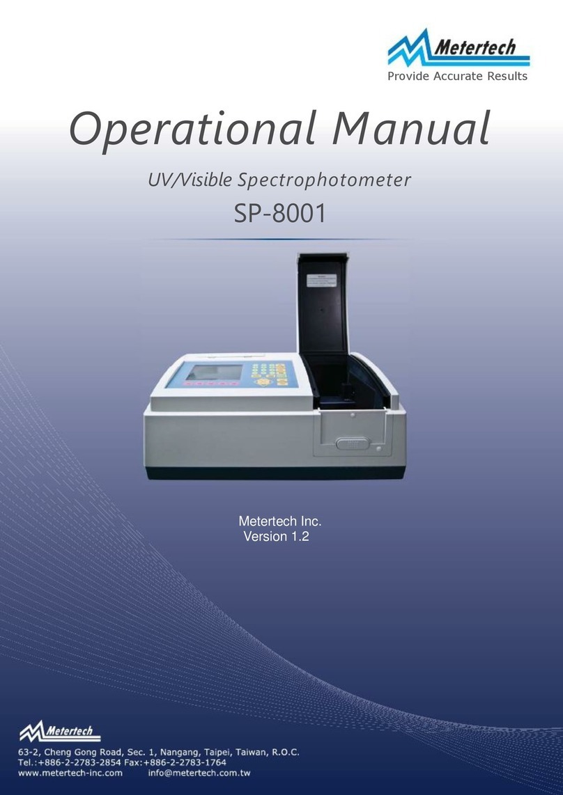
Operational
Manual
Miniphotometer
Model 6+
PN 475101

Product Warranty
Your Eurofins Abraxis Model 6+ Miniphotometer is guaranteed to be free of defects
in workmanship and materials under normal use for a period of one year from the
date of purchase by the customer.
The liability of Eurofins Abraxis is limited to repair or replacement and in no event
shall Eurofins Abraxis be liable for any collateral or consequential damages ot loss.
Instruments subject to misuse, abuse, neglect or unauthorized reair or modifications
will be excluded from this warranty.
This guarantee specifically excludes expendables and consumables.
All warranty claims must be directed to Eurofins Abraxis distributor responsible for
the sale of the instrument.
Eurofins Abraxis, Inc Tel.: (215) 357-3911
124 Railroad Drive Fax: (215) 357-5232
Warminster, PA 18974 Email: info.ET.Warminster@eurofinsus.com
WEB: www.abraxiskits.com Technical Support: support.ET.Warminster@eurofinsus.com

Contents
Section 1Installation -------------------------------------------------------------------------------- 1
1-1
Unpacking------------------------------------------------------------------------------------- 1
1-2
Standard Equipment --------------------------------------------------------------------- 1
1-3
Whole Unit---------------------------------------------------------------------------------- 1
1-4 Installation
--------------------
2
Section2General system information
--------------------
3
2-1 General Introduction
--------------------
3
2-2 Specifications
--------------------
3
Section 3Function description
--------------------
5
3-1 Modes
--------------------
5
3-2 Convertibilities
--------------------
5
3-2-1Well-strip Holder
--------------------
6
3-2-2Cuvette Holder
--------------------
6
3-2-3Interference Filters
--------------------
6
3-3 Control Button Instruction
--------------------
7
3-4 RS-232 Interface
--------------------
7
3-5 Centronic Interface
--------------------
7
Section 4Operation
4-1 Absorbance Mode
--------------------
--------------------
8
8
4-2 Concentration Mode(without standard)
--------------------
9
4-3 Concentration Mode(with standard)
--------------------
10
4-4 Cut Off Mode
--------------------
11
4-5 Print Function
--------------------
12
4-6 RS232 Function
--------------------
12
4-7 ABS Calibration Function
--------------------
12
4-8 Operation with well-strip
--------------------
13
Section 5Maintenance
--------------------
14
5-1 Notice
--------------------
14
5-2 Error Messages
--------------------
14
Appendix M6+mate Installation and Operation
--------------------
15

1
Section 1
Installation
1-1
Unpacking
The packing contains the items stated below. Unpack the carton and inspect carefully. If any
part is damaged or missing, contact your dealer immediately.
Save the packing materials in case the unit may need to be repacked or returned for service.
1-2
Standard Equipment
Q’ty
DESCRIPTION
PART NO.
1
Model 6
+
Miniphotometer
1
Optical unit(two-in-one as awhole unit)
M006-001
1
450nm interference filter
M006-450
1
Well-strip holder
M006-006
1
Cuvette holder (round)
M006-003
1
Power adapter (110V) or
M006-009
1
Power adapter (220V)
M006-010
1
Operator’s manual
M006-012
1-3
Whole Unit

2
1.
LCD Display 6. Filter
2.
Touch Buttons 7-a. Well-strip Holder
3.
Centronic Receptacle 7-b. Round Cuvette Holder
4.
RS-232 Receptacle 7-c. Square Cell Holder
5.
Power Adapter/ 8. Power Adapter Battery Receptacle
1-4
Installation
1.
Check if the supplied power adapter is at right voltage to be used.
2.
Insert the phone plug of the power adapter or optional battery bag into the receptacle
located at the left of the front side of the unit.
3.
Connect with your PC or printer if desired.
4.
LCD of the unit will display the greeting message “Metertech,Miniphotometer” and then
“SYSTEM MENU,..1:ABS MODE”
Refer details of operation in Section 4.

3
Section 2
General system information
2-1
General Introduction
The Convertible Well-strip/Cuvette Reader Model 6+is aportable miniphotometer designed to do
ELISA testings in either 1x8/1x12 microwell strips or round/square cuvettes by interference filter
for wavelength of 400-700nm.
Model 6+is auser-friendly ELISA reader. All operations are carried out with only two touch buttons
by following instruction on the LCD display, and results can be obtained within two seconds.
Model 6+undertakes testings with an extreme economic Reagent consumption, in microwell at
0.3ml and in cuvette at 0.5ml.
The installed RS-232 and centronic interfaces allow Connections to computer and optional printer.
Model 6+also can be connected with any 12V battery bag or field operations.
In short, Model 6+is avery ideal instrument for doctor’s use either in the office or on the field
operation.
2-2
Specifications
Wavelength Range 400-750nm
Filters Narrow band interference filters
Bandwidth :10nm +/-2nm
Standard :450nm
Photodetector Solid-state silicon photodiode
Display LCD 16x2 characters
External Outputs RS-232 interface
Parallel printer interface
Light Source Focalized tungsten lamp 6V/2W
Absorbance Range 0.000 –2.500 Abs
Linearity 0.000 –1.500 Abs +/-2.0%
Concentration Range 00000.00 –99999.99
Reproducibility <+/-0.005 Abs (under 2.000 Abs)
Resolution 0.001 Abs (under 2.000 Abs)
Data Storage 125 Sets
Power(Adapter) Input AC 120V/240V

4
Output
DC 12V/700mA
Sample Compartment
Strip
:9x13mm standard well-strip
Cuvette: Round 12mm in diameter
Dimension
Whole unit:
150mm(W)
170mm(D)
50mm(H)
Optical unit: 50mm(W)
50mm(D)
50mm(H)
Weight 850 grams (with power adapter)
Options 1. 10mm square cuvette holder
2.
Centronic cable
3.
RS-232 cable
4.
Thermal printer (40 column)

5
Section 3
Function description
Model 6+uses alow voltage Tungsten lamp for sample illumination. Lamp life is conserved by being
only turned on for the brief measurement period after abutton is pressed to blank or read asample.
Light from the lamp is collected by the condenser lens set and focalized to anarrow beam in the
sample well/cuvette below. The analyzing beam then passes through interference filter which passes
only the wavelength of interest, on to the photodiode.
The photo-signal is amplified by ahigh gain amplifier and converted to adigital signal by an analog to
digital converter. This digital signal is processed by the microcomputer and the computed units
are presented by the 16x2 character alpha-numeric display.
3-1
Modes
Model 6+can read ABSORBANCE and calculate CONCENTRATION.
Three modes are selectable:
1.
Absorbance mode
2.
Concentration mode (with no standard)
3.
Concentration mode (with standard)
4.
Cut Off mode
3-2
Convertibilities
Model 6+is aconvertible photometer in reading both well-strip and cuvette at 400-750nm
wavelength.

6
3-2-1
Well-strip Holder
The supplied standard well-strip
holder can fit 9x13mm well-strip
(1x8 or 1x12). Turn the optical
unit in position as fig 3-1
(Note: figures of filter in right
reading way) to install/remove the
holder.
3-2-2
Cuvette Holder
Remove well-strip holder, and
turn counterclockwise for 90
degrees to install cuvette holder
as Fig 3-2.Return to well-strip
reading in opposite direction.
One standard round cuvette holder
(12mm in diameter) is supplied with
the unit. Optional square cuvette
holder(10x10mm) can be purchased
separately.
3-2-3
Interference filters
Refer easy access of exchange of
filter as Fig 3-3.
One standard 450nm filter is supplied
with the unit. Options of 405/490/
550/600/650nm and other filters can
be purchased separately.
Fig. 3-2
Fig. 3-3

7
3-3
Control Button Instruction
Model 6+is fully operated only with two touch buttons.
READ/ENTER button controls
-
to enter the selected mode
-
to read Blank, Standard, and Sample
-
to move cursor when keying in Factor and Standard
Concentration values
SEL/ESC button controls
-
to select different mode
-
to return to SYSTEM MENU, previous action
-
to key in Sample name, Factor and Standard
-
Concentration value
** 1. Standard Concentration and Factor values are keyed in order form left to right;
Standard value is limited in 00000.0-99999.9, Factor value in 0000.00-9999.99.
2.
SEL/ESC button keys in figures 0-9 in rotation.
3.
READ/ENTER button can only move cursor rightwards.
4.
When awrong figure is keyed in, you need to press SEL/ESC button to exit the existing
mode and return to “SYSTEM MENU”.
3-4
RS-232 Interface
This is interface for connection to your PC. The optional RS-232 cable should be purchased
separately. The access is as follows:
9-pin female cable
(1)
1-
------------(2) RXD
2-
------------(3) TXD
(4)
3-
------------(5) SG
.
.
.
(9)
3-5
Centronic Interface
This interface controls connection with an optional portable printer or your printer. The
optional 20pin/36pin centronic cable should be purchased separately.

8
Section 4
Operation
Power is supplies to the unit from an adaptor or from any 12VDC battery bag.
After power is turned on, LCD displays the greeting message “Meteretch, Miniphotometer”
and followed by “SYSTEM MENU, 1:ABS MODE”. Then you may proceed your required mode
in either well-strip or cuvette as procedures stated below.
4-1
Absorbance Mode
01
Press READ/ENTER button.
02
LCD displays “ABS MODE, READ BLANK”.
03
Insert the blank well or place the blank cuvette into the read position.
04
Press READ/ENTER button.
05
The unit reads and zeroes the blank well/cuvette, and LCD displays “00 0.000ABS, READ
SAMPLE”.
06
Push the first sample well or place the first sample cuvette into the read position.
07
Press READ/ENTER button
08
The Absorbance of the first sample is read and LCD displays “01 X.XXXABS, SET NAME
MX”.
09
Press SEL/ESC button to select the sample name from M0 to M9 and MX. The data with name
from M0 to M9 will be saved in memory; areading with name MX will not be saved in
memory. The newest measured data is put on the top of memory space.
10
Press READ/ENTER button.
11
LCD displays “01 X.XXXABS MX, READ SAMPLE”.
12
Push the next sample well or place the next sample cuvette to continue as steps 07-11 and
results of samples will be led by 02, 03 ……… 99,00,01,02 ………, unless to quit the
existing readings of samples to ………
12-1
Re-zero anew blank by pressing SEL/ESC button to
return to step 02.
12-2
Or exit the Absorbance mode for another new mode
by pressing SEL/ESC button twice. This will return
to the display “SYSTEM MENU, 1:ABS MODE”.
Note: 1. If filter is not properly installed, LCD will display “READ ERROR”. Check and
ensure the filter is in right position, and press READ/ENTER button to
repeat the last action.
2.
If you want to erase data stored in memory,please
return to System Menu, then press SEL/ESC and READ/ENTER buttons.
LCD displays “ENG MENU, 1:ADC READING”. Press SEL/ESC button, LCD
shows “2:CLEAR MEMORY”. Press READ/ENTER button, all the stored data
will be deleted.

9
4-2
Concentration Mode (with no standard)
01
Press SEL/ESC button from “SYSTEM MENU, 1:ABS MODE”.
02
LCD displays “SYSTEM MENU, 2:A-CONC MODE(1)”.
03
Press READ/ENTER button. LCD displays “KEY IN FACTOR, FACTOR=0000.0”.
04
Key in Factor value (0000.0-9999.9) as instructed in Section 3-3-**.
05
LCD displays “A-CONC MODE(1), READ BLANK”.
06
Insert the blank well or place the blank cuvette into the read position.
07
Press READ/ENTER button.
08
The unit reads and zeroes the blank well/cuvette, and displays “00 00000.00C, READ
SAMPLE”.
09
Push the first sample well or place the first sample cuvette into the read position.
10
Press READ/ENTER button.
11
The concentration of first sample is calculated, and displays “01 XXXXX.XXC, SET NAME MX”.
12
Press SEL/ESC button to select the sample name from M0 to M9 and MX.
13
Press READ/ENTER button.
14
LCD displays “01 XXXXX.XXC MX, READ SAMPLE”.
15
Push the next sample well or place the next sample cuvette to continue as steps 10-14 and
results of samples will be led by 02, 03 ……… 99, 00, 01, 02, ………, unless to quit the
existing readings of samples to ………
15-1
Re-zero anew blank by pressing SEL/ESC button to return to step 05. 15-2
Or exit the Concentration (with no standard) mode for another new mode by
press DEL/ESC button twice. This will return to the display “SYSTEM MENU,
1:ABS MODE”.
Note: If “READ ERROR” is displayed on LCD, refer Note in
Section 4-1 for
asolution.

10
4-3
Concentration Mode (with standard)
01
Press SEL/ESC button twice from display “SYSTEM MENU, 1:ABS MODE”.
02
LCD displays “SYSTEM MENU, 3:A-CONC MODE(2)”.
03
Press READ/ENTER button, LCD displays “KEY IN CONCEN, CONCEN=00000.00C”.
04
Key in Concentration value(00000.00-99999.99) of standard as instructed in Section 3-3-**.
05
LCD displays “A-CONC MODE(2), READ BLANK”.
06
Insert the blank well or place the blank cuvette into the read position.
07
Press READ/ENTER button.
08
The unit reads and zeroes the blank well/cuvette, and display “00 0.000ABS, READ
STANDARD”.
09
Push the standard well or place the standard cuvette into the read position.
10
Press READ/ENTER button.
11
The units reads the standard and calculates its Factor value, and displays “FACTOR=XXXX.X,
READ BLANK”.
12
User can test sample blank by following step 12-15, or press SEL/ESC button and jump to
step 16 to measure sample directly.
13
Insert the blank well or place the blank cuvette into the read position.
14
Press READ/ENTER button.
15
The unit reads and zeroes the blank well/cuvette, and displays “00 00000.00C, READ
SAMPLE”.
16
Push the first sample well or place the first sample cuvette into the read position.
17
Press READ/ENTER button.
18
The Concentration of first sample is calculated, and displayed as “01 XXXXX.XXC, SET
NAMEMX”
19
Press SEL/ESC button to select the sample name from M0 to M9 and MX.
20
Press READ/ENTER button.
21
LCD displays “01 XXXXX.XXC MX, READ SAMPLE”.
22
Push the next sample well or place the next sample cuvette to continue as steps 16-20 and
results of samples will be led by 02, 03 ……… 99, 00, 01, 02, ………, unless to quit the
existing readings of samples to ………
21-1
Re-zero anew blank by pressing SEL/ESC button to return to step
13.
21-2
Or exit the Concentration (with standard) mode for another new mode by press
DEL/ESC button twice. This will return to the display “SYSTEM MENU, 1:ABS
MODE”.
Note: 1.
If “READ ERROR” is displayed on LCD, refer Note in Section 4-1 for a
solution.
2.
If the calculation result of standard Factor exceeds 9999.99, LCD
will display “FACTOR ERROR”. Press READ/ENTER button will return
to step 03, user can key in correct standard value, and do proper
standard measurement again.

11
4-4
Cut Off Mode
01
Press SEL/ESC button three times from display “SYSTEM MENU,1:ABS MODE”.
02
LCD displays “SYSTEM MENU,4:CUT OFF MODE”.
03
Press READ/ENTER button, LCD displays “KEY IN COEFF A, A=0.000”.
04
Key in positive control coefficient A(0.000-9.999) of standard as instructed in Section 3-3-
**.Please read note 1below for the formula of cut off value(COV).
05
Key in negative controlcoefficient B, cut off control coefficient C, Dand offset E.
06
If the keyed in coefficients makes the resultant value of COV zero, “KEY IN ERROR”will
be displayed. Press SEL/ESC button and return to step 03 to correct coefficients.
07
After finishing above step, LCD displays “CUT OFF MODE, READ BLANK”. Press
SEL/ESC button and return to step 3for coefficient checking, or follow the next step.
08
Insert the blank well or place the blank cuvette into the read position.
09
Press READ/ENTER button.
10
The unit reads and zeroes the blank well/cuvette, and LCD displays “00 0.000ABS, READ
PC”.
11
Push the standard well or place the standard cuvette (positive control solution) into the read
position.
12
Press READ/ENTER button. LCD displays “PC= X.XXXABS, READ NC”.
13
Push the standard well or place the standard cuvette (negative control solution) into the
read position.
14
Press READ/ENTER button. LCD displays “NC= X.XXXABS, READ COC”.
15
Push the standard well or place the standard cuvette (cut off control solution) into the read
position.
16
Press READ/ENTER button. LCD displays “COC= X.XXXABS, CALCULATE COV”.
17
Press READ/ENTER button. LCD displays “COV= X.XXXABS, SET NAME MX”.
18
Press SEL/ESC button to select COV name from M0 to M9, and MX.
19
Press READ/ENTER button. LCD displays “COV= X.XXXABS MX, READ BLANK”
20
Press SEL/ESC button and directly jump to step 21, or insert the blank well or place the blank
cuvette into the read position then press READ/ENTER button.
21
LCD displays “00 0.000ABS, READ SAMPLE”.
22
Push the sample well or place the sample cuvette into the read position, then press
READ/ENTER button.
23
LCD displays “01 ++++++++, SET NAME MX”. Please refer to
note 2below for
sign(++++++++) explanation.
24
Press SEL/ESC button to select sample name from M0 to M9, and MX.
25
LCD displays “01 ++++++++ MX, READ SAMPLE”.
26
Repeat step 22 to step 25 for the rest of sample measurement, or press SEL/ESC
button to go back to System Menu.
Note: 1. COV =(A xPC +BxNC +CxCOC) xD+E
Where COV is Cut Off Value.
2.
If the sample absorbance is larger than calculated COV, LCD shows
“++++++++”. If smaller than COV, “--------”
will be displayed. If
|COV –sample reading| <0.020ABS, LCD shows “********”.
3.
If obtained COV is larger than 2.500ABS, “COV ERROR” will be
displayed. Press SEL/ESC button and return to step 03 to start over,
or follow step 08 to read standard solutions again.

12
4-5
Print Function
01
Press SEL/ESC button four times from display “SYSTEM MENU,1:ABS MODE”.
02
LCD displays “SYSTEM MENU,5:PRINT”.
03
Press READ/ENTER button, LCD will sequentially display 125 sets of stored data with the
form “XXX X.XXXABS MX”.
04
Press READ/ENTER button, LCD will stay at one reading.
05
Press READ/ENTER button again, LCD will continue update new reading to the final
reading. Press SEL/ESC button, the display will go back to “SYSTEM MENU, 1:ABS
MODE”.
06
If the printer is already connected to the machine, all the data will be printed out.
Note: If printer is connected to the machine while operating at above any mode,
the displayed blank data, sample data and standard data will also be printed.
4-6
RS-232 Function
01
Press SEL/ESC button five times from display “SYSTEM MENU,1:ABS MODE”.
02
LCD displays “SYSTEM MENU,6:RS232”
03
Connect PC COM port to the machine serial port through RS-232 cable.
04
Press READ/ENTER button, LCD displays “RS232, M6----- PC”. The machine is waiting for,
accepting and executing PC command such that the stored data is transmitted to PC. After
finishing this work, press SEL/ESC button to return to main menu.
4-7
ABS Calibration Function
01
Press SEL/ESC button six times from display “SYSTEM MENU, 1:ABS MODE”.
02
LCD display “SYSTEM MENU, 7:CALIBRATION”.
03
Press READ/ENTER button, LCD displays “ABS CALIBRATION, COEFF=1.000”.
04
Press READ/ENTER button, LCD displays “ABS CALIBRATION, 1:KEY IN COEFF”. User can press
SEL/ESC button to select “1:KEY IN COEFF” by following step 05 ,or “2:READ STANDARD”
following step 06.
05
Press READ/ENTER button, LCD displays “KEY IN COEFF, COEFF= 1.000”. Key in coefficient
value as instructed in Section 3-3-**.Press SEL/ESC button to go back to SYSTEM MENU.
06
PressREAD/ENTER button, LCD displays “KEY IN STANDARD, ABS=0.000”. Key in standard ABS
value as instructed in Section 3-3-**.
07
Press READ/ENTER button, LCD displays “CALIBRATION, READ BLANK”. Insert the blank
well or place the blank cuvette into the read position.
08
Press READ/ENTER button, and LCD displays “00 0.000ABS, READ STANDARD”.
09
Push the standard well or place the standard cuvette into the read position.
10 Press READ/ENTER button, and LCD displays “ABS CALIBRATION, COEFF=X.XXX”. Press
SEL/ESC button and go back to SYSTEM MENU.
Note: The default coefficient value is 1.000, and any change through above steps
will be saved in memory. The coefficient is used as amultiplier for all ABS
reading of four measurement modes.Measurement errors can be reduced by
this calibration procedure.

13
4-8
Operation with Well-Strip
(A)
Position of Strip
The reading position is located at the center of path that strip passes. There are three wells
from reading position to either entry or exit of the path.
Take 8-well strip for instance, the first (last) well is at reading position when five wells expose
on entry (exit) end.(Fig. 4-1)
(B)
Insertion of Strip
Horizontally insert and slightly push the strip until the first well is held for reading. Declining
insertion either upwardson downwards is incorrect.(Fig. 4-2)
Fig. 4-2
Fig. 4-1

14
Section 5
Maintenance
5-1
Notice
Besides exchange of well-strip/cuvette and filters as mentioned earlier, Model 6+has no user
replaceable or adjustable components inside the cover. Do not remove the cover unless specifically
authorized by your dealer or the manufacturer.
Return it for servicing if your Model 6+cannot be operated properly as instructed in this Manual.
5-2
Error Messages
You may refer solution for the following error messages in Section 4–Notes.
1.
“READ ERROR”
2.
“FACTOR ERROR”
3.
“KEY IN ERROR”
4.
“COV ERROR”

15
Appendix
M6+mate Installation and Operation
A1. PC system requirement
-CPU model need be newer than Pentium-100, equipped with CD driver.
-Microsoft Windows 95 +IE5.0 or Microsoft Windows 98.
-Video card capable supporting 800X600 pixels and 16 bit(Hi color) color resolution at least.
-Mouse, keypad, one serial communication port(COM 2) for RS232 and one 9pin connector.
A2. About the CD-ROM
-An executable program ‘M6plus’ written on this CD, is the main program for downloading the
stored data on the M6+ machine to the PC.
A3. M6+mate installation
-Select the installation program ‘Setup.exe’ under the ‘M6plus’ directory, and make execution.
-Please follow instructions to complete the installation work. Aprogram ‘M6plus.exe’ will be
generated under C:\program files\M6plus directory.
A4. Online operation
-Make sure 9-pin connector is plugged on the RS-232 output of M6+ and COM2 of PC.
-Power on PC and M6+, press SEL/ESC button five times on M6+. LCD shows ‘SYSTEM MENU,
6:RS232’. Then press READ/ENTER button, LCD shows ‘RS232, M6 PC’.
-Go to Program Files of Windows 95 or 98, find ‘Model6 plus’ fileunder ‘Metertech’ and click it.
The M6plus is executed and anew window comes up.
-Click ‘Setting’ on the menu bar and click ‘Comport port’ under it, and adialog box ‘COM Port
Setting’ will show up. The default setting is COM2 and user can select whichever is suitable for
real circumstances. After selecting the proper port, press ‘Port Open’ button to proceed.
-Click ‘Manipulate’ on the menu bar, then click ‘Get Data’ under it. The data stored on the M6+
machine will be transmitted and displayed on the screen. All the data are decreasingly
numbered with max number 125 at the start. The newest measured data is located at the top of
data column.
-Click ‘File’ on the menu bar, you will find two choices ‘Data Save’ and ‘Data Print’. Click ‘Data
Print’, all the data shown on the screen will be printed out. Click ‘Data Save’, you can create a
file to save the current data in different location for further uses(for example using Excel tool to
do data processing).
This manual suits for next models
1
Table of contents
Other Metertech Measuring Instrument manuals
Popular Measuring Instrument manuals by other brands
Check-line
Check-line MKM user manual
Kyoritsu Electrical Instruments Works, Ltd.
Kyoritsu Electrical Instruments Works, Ltd. 6300 instruction manual
red lion
red lion PAXLCL Series manual
EL-CELL
EL-CELL ECD-3 user manual
Pro's Kit
Pro's Kit MT-4617LED user manual
EPE Conseil
EPE Conseil ESI 22 quick start guide
Alfalaval
Alfalaval TE67P Series instruction manual
i-PRO
i-PRO WJ-NX310K Series Important information
Delta
Delta LTL-XL manual
Kyoritsu Electrical Instruments Works, Ltd.
Kyoritsu Electrical Instruments Works, Ltd. KEW8146 instruction manual
AquaLab
AquaLab Series 3 Operator's manual

PerkinElmer
PerkinElmer L6050002B Quick setup guide
