metex TESTLAB Y122HU User manual

DIGITAL
MULTIMETER
Cat.
No.
Y122HU(M3850)
Operating
Manual
PINCroy
(
al
ae
SET/pe.
ie
oe,
iia
By.
a
<=
te,
TUV
Rheinland
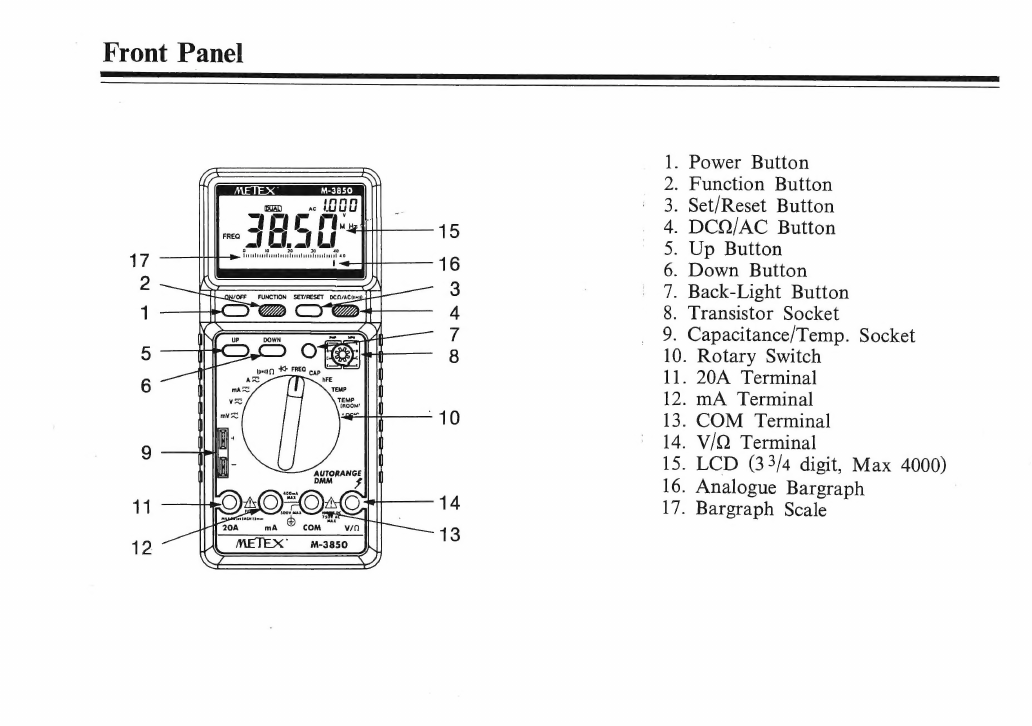
Front
Panel
.
Power
Button
.
Function
Button
.
Set/Reset
Button
.
DCQ/AC
Button
Up
Button
.
Down
Button
.
Back-Light
Button
.
Transistor
Socket
_
9.
Capacitance/Temp.
Socket
C5
O
Tee
10.
Rotary
Switch
te
11.
20A
Terminal
12.
mA
Terminal
13.
COM
Terminal
14.
V/QO
Terminal
15.
LCD
(33/4
digit,
Max
4000)
16.
Analogue
Bargraph
17.
Bargraph
Scale
19
20
21
22
23 30
31
H)(O
H)(MIN}(MAX)(REL)
pq
FREO
oT
OTe
WG
Ox]
24.
25.
26.
27,
28
(ACL)[RH)(ouaL)(CcOMIEE
AC
PADIS
IA
29
(ai
Ne
-_,
=,
*"
ic
32,
33
acwin
B
4
')
yd
)
x
)
AE
MkH
34
,
35
37
39
Te
CO
(04
2
pmVA
CAP
o
ine
MK
hFE
'
LOGI
Crete
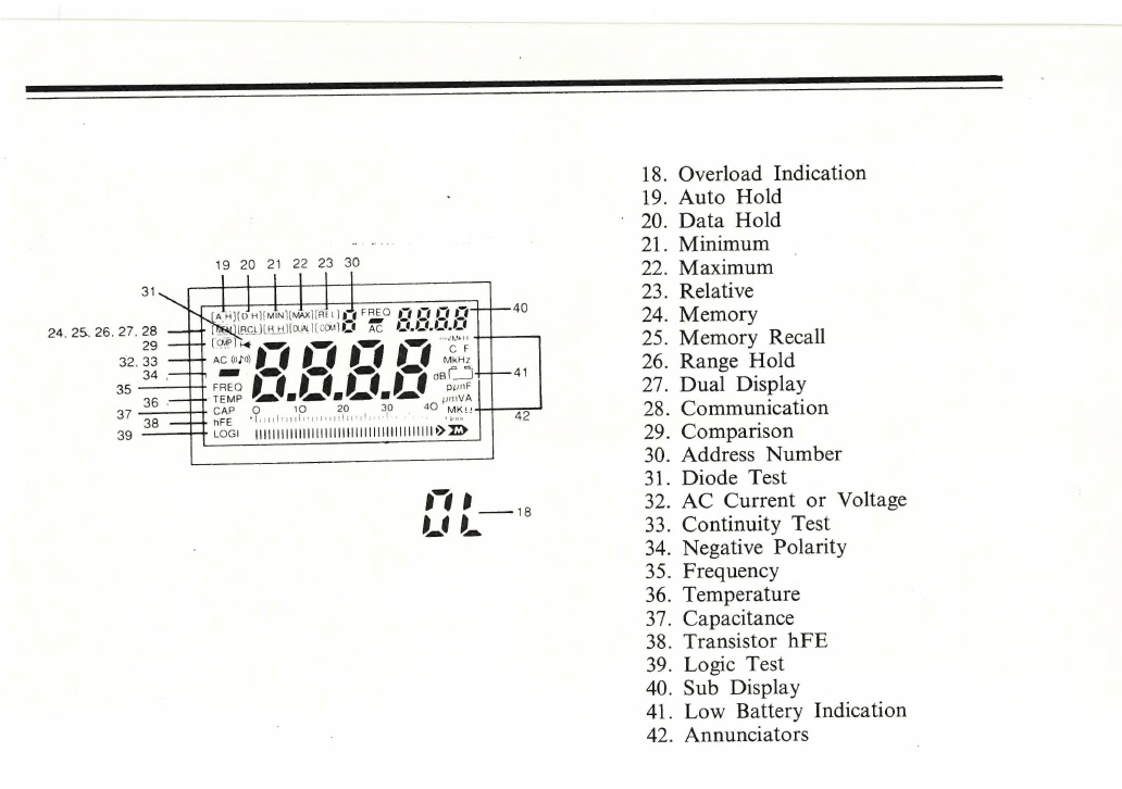
.
Overload
Indication
.
Auto
Hold
.
Data
Hold
.
Minimum
.
Maximum
.
Relative
.
Memory
.
Memory
Recall
.
Range
Hold
.
Dual
Display
.
Communication
.
Comparison
.
Address
Number
.
Diode
Test
.
AC
Current
or
Voltage
.
Continuity
Test
.
Negative
Polarity
.
Frequency
.
Temperature
.
Capacitance
.
Transistor
hFE
.
Logic
Test
.
Sub
Display
.
Low
Battery
Indication
.
Annunciators

SS
a
RB
SB
TY
a
Safety
Information
This
meter
has
been
manufactured
and
tested
in
accordance
with
IEC348
and
DINS57411/
VDE0411
part
1:
Safety
requirement
for
elec-
tronic
measuring
apparatus,
safety
class
II
This
manual
contains
information
and
warnings
which
must
be
observed
to
assure
safe
operation.
Safety
Symbols
The
following
symbols
have
been
placed
on
the
meter
to
remind
you
of
measurement
limitations
and
safety.
20A
The
maximum
current
that
can
be
measured
at
this
terminal
is
20A
DC/AC.
This
terminal
is
fuse
prot-
ected.
When
using
this
range
with
high
current
keep
the
duty
cycle
to
30
seconds
on
load,
15
minutes
off
load.
mA
The
maximum
current
that
you
can
measure
at
this
terminal
is
400mA
DC/AC.
This
terminal
is
protected
by
a
400mA
fuse.
MAX
===1000V
750V
2
AN
[a]
To
avoid
electric
shock
or
damage
to
instrument,
do
not
connect
the
com-
mon
input
terminal
to
any
source
of
more
than
500
volts
with
respect
to
ground/earth.
The
maximum
voltage
this
meter
can
measure
is
1000V
DC
or
750V
AC.
Be
exceptionally
careful
when
me-
asuring
high
voltages.
DO
NOT
TOUCH
THE
TERMINALS
OR
PROBE
TIPS.
Refer
to
the
instructions.
complete
operating
This
symbol
indicates
class
II,
double
insulation.

Safety
Warnings
To
avoid
electric
shock
and/or
damage
to
the
meter,
do
not
attempt
to
measure
any
voltages
exceeding
1000V
DC
or
750V
AC.
To
avoid
damage
to
the
meter
and/or
possible
personal
injury,
observe
the
input
limits
as
stat-
ed
in
table
1.
To
avoid
damage
to
the
meter,
disconnect
the
test
leads
from
the
test
points
before
changing
the
function/range.
To
avoid
electric
shock,
be
careful
when
work-
ing
with
voltages
above
60V
DC
or
25V
AC
as
these
voltages
pose
a
shock
hazard.
The
20A
current
range
is
protected
by
a
fuse.
To
'
avoid
damage
or
personal
injury,
only
use
this
meter
with
circuits
which
are
protected
with
a
cir-
cuit
breaker
or
fuse
of
up
to
20A
or
4000VA.
Do
not
apply
voltage
between
the
20A
or
mA
and
COM
terminals.
Do
not
allow
the
meter
or
test
leads
to
get
wet.
Before
making
any
measurements,
make
sure
that
the
test
leads
are
in
good
condition.
Table
1.
FUNCTION
V
DC
V
AC
INPUT
LIMITS
750V
AC
250V
DC/AC
400mA
DC/AC
TERMINAL
V/Q+COM
V/Q+COM
V/Q+COM
mA
DC/AC
200A
DC/AC
|
20A+COM
Diode/Buzzer
|
V/Q+COM|
250A
DC/AC
V/Q+COM|
750V
DC/AC
Logic
VIQ+COM|
250V
DC/AC

Preparing
for
operation
Installing
the
Battery
Your
meter
require
a
9V
battery
for
power.
The
-
symbol
appears
when
the
battery
voltage
drops
to
certain
limits.
For
correct
operation,
replace
the
battery
as
soon
as
possible.
Contin-
ued
use
with
a
low
battery
will
lead
to
errors
in
readings.
WARNING:
TO
AVOID
ELECTRIC
SHOCK,
DISCONNECT
BOTH
LEADS
FROM
ANY
EQUIPMENT
BEFORE
YOU
REMOVE
OR
INSTALL
THE
BATTERY.
The
battery
can
be
installed
by
the
following
procedure
:
1.
Turn
off
the
power
and
disconnect
the
two
test
leads.
2.
Remove
the
screw
to
open
the
battery
com-
partment.
3.
Place
the
battery
inside
the
insulation
capsule
and
snap
it
into
place.
WARNING:
DO
NOT
DISCARD
THE
INSU-
LATION
SLEEVE.
FAILURE
TO
USE
THIS
SLEEVE
MAY
CAUSE
DAMAGE
TO
THE
METER
AND
POSSIBLE
PERSONAL
IN-
JURY.
4.
Replace
the
battery
compartment
cover
and
screw
down.
WARNING:
DO
NOT
OPERATE
THIS
MET-
ER
UNTIL
THE
BATTERY
COVER
PLATE
HAS
BEEN
REFITTED.
Test
Leads
Use
only
the
leads
supplied
with
your
meter.
These
test
leads
are
rated
for
1200
volts.
Caution
:
Although
the
test
leads
are
rated
for
1200
volts,
the
maximum
input
voltage
to
the
meter
is
1000V
DC
or
750V
AC
RMS,
you
may
damage
‘the
meter
and
expose
yourself
to
a
serious
shock
hazard.
Always
use
extreme
care
when
measur-
ing
high
voltages.
Never
connect
the
COM
terminal
to
any
source
greater
than
500V
with
respect
to
ground.
This
will
creat
a
serious
shock
hazard.

Using
the
meter
1.
Power
ON/OFF
button
Press
the
ON/OFF
button
to
turn
the
meter
ON,
press
the
button
again
to
turn
the
meter
OFF.
Automatic
Power
off
The
automatic
power
off
feature
extends
the
life
of
the
batteries
by
turning
the
meter
off
if
neit-
her
the
rotary
switch
or
the
buttons
have been
operated
for
ten
minutes.
However
if
the
COM
mode
is
on
or
the
temperature
range
is
selected
the
automatic
power
off
feature
is
disabled.
2.
Function
button
The
AH(auto
hold)indicator
will
be
displayed
on
the
LCD
when
the
meter
is
turned
on.
Each
pres-
s
of
the
function
button
will
display
a
function,
when
the
function
as
each
function
is
displayed
you
may
select
or
deselect
the
function
by
press-
ing
the
SET/RESET
button.
The
sequence
that
the
functions
are
displayed
is
as
follows
:
AH~
DH-MIN
—~MAXK->REL~MEM-~>RCL-RH
—COM->DUAL->CMP
4.
DCQ/AC
©
Press
the
DCQ/AC
button
to
toggle
between
AC
and
DC
when
the
rotary
switch
is
set
to
vol-
tage
or
current,
or
between
resistance
and
conti-
nuity
when
the
rotary
switch
is
set
too)
©
5&6.
UP
DOWN
buttons
Press
the
UP
or
DOWN
buttons
to
determine
the
polarity,
value
and
range
of
the
reference
val-
ue
in
the
REL
and
CMP
modes,
these
buttons
are
also
used
to
address
the
stored
reference
val-
ues
in
the
MEM
and
RCL
modes,
and
to
in-
crease/decrease
the
range
value
in
the
RH
mode.
7.
Back
light
Pressing
the
yellow
button
will
turn
on
the
back
light,
this
will
make
readings
much
easier
in
poor
lighting
conditions.
The
light
will
remain
on
for
25
seconds.
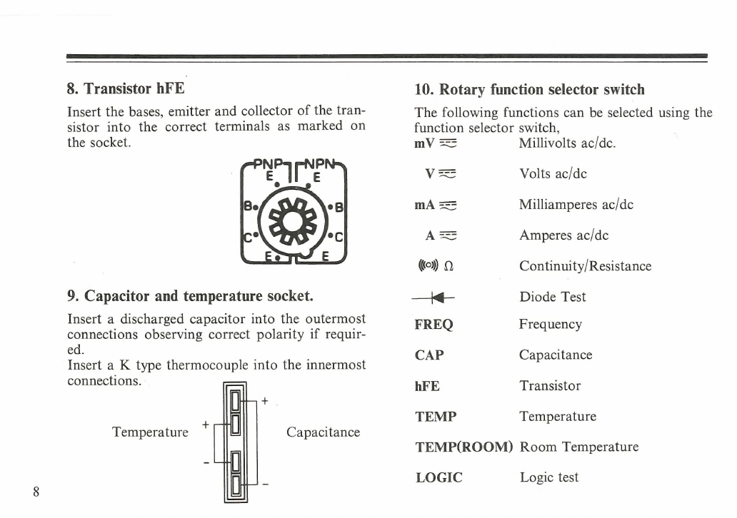
8.
Transistor
hFE
Insert
the
bases,
emitter
and
collector
of
the
tran-
sistor
into
the
correct
terminals
as
marked
on
the
socket.
ee
9.
Capacitor
and
temperature
socket.
Insert
a
discharged
capacitor
into
the
outermost
connections
observing
correct
polarity
if
requir-
ed.
Insert
a
K
type
thermocouple
into
the
innermost
connections.
io
:
I
+
Temperature
|
o-
Capacitance
10.
Rotary
function
selector
switch
The
following
functions
can
be
selected
using
the
function
selector
switch,
mV
==
Millivolts
ac/dc.
Ve
Volts
ac/dc
mA
===
Milliamperes
ac/dc
=
Amperes
ac/dc
(©)
Oo
Continuity/Resistance
—_\<q—
Diode
Test
FREQ
Frequency
CAP
Capacitance
hFE
Transistor
TEMP
Temperature
TEMP(ROOM)
Room
Temperature
LOGIC
Logic
test

11.
20A
Amperes
input
terminal
For
Current
measurements
of
up
to
1OA
AC
or
DC.
12.
mA
Milliamp
input
terminal
For
current
measurements
of
up
to
400mA
AC
or
DC.
13.
COM
Common
terminal
Return
terminal
for
all
measurements.
14.
V/X
©)
Volt,
resistance,
continuity,
diode,
frequency,
log-
ic
test
terminal.
15.
Digital
display
Digital
readings
are
displayed
on
a
4000
count
display
with
automatic
polarity
and
decimal
point
placement.
16.
Wninnnncnnnnnnneneiinnimiindx>
Analog
Bar
Graph
The
bar
graph
consists
of
43
segments
that
il-
luminate
from
left
to
right
as
the
input
increases.
It
functions
in
much
the
same
way
as
the
needle
on
an
analogue
meter
but
without
the
mechan-
ical
overshoot
inherent
in
meter
movements.
If
the
input
exceeds
the
measuring
range
selec-
ted,
OL
is
displayed,
the
bar
graph
flashes
and
a
bleeping
noise
is
heard.
17.
Perrin
ernie
te
Bar
Graph
Scale
Scale
for
absolute
readings.
18.
OL
Overload
Indication
OL
is
diaplayed
with
the
measurement
exceeds
the
measuring
range
selected.
Tun
init
ili
fast
wii
Tut
uae
MMMM
TT
>
19.
AH
Auto
Hold
The
meter
displays
a
reading
automatically
rec-
orded
2
seconds
previously.
20.
DH
Data
Hold
In
this
mode,
a
reading
can
be
stored
on
the
sub
display
by
pressing
the
SET/RESET
button,
the
main
display
will
display
all
subsequent
readings.

21.
MIN
Minimum
The
sub
display
shows
the
maximum
reading
whilst
the
main
display
shows
present
reading.
22.
MAX
$=/Maximum
The
sub
display
shows
the
maximum
reading
whilst
the
main
display
shows
the
present
read-
ing.
23.
REL
_
Relative
Enables
you
to
compare
a
reference
reading
with
subsequent
readings.
To
set
the
reference
value
proceed
as
follows
:
1.
Set
the
function
mode
to
REL
2.
Store
the
polarity,
values
and
range
of
the
ref-
erence
value
by
pressing
the
UP
DOWN
and
SET/RESET
buttons.
3.
Press
the
SET/RESET
button
for
the
final
set-
ting
and
the
meter
will
return
to
manual
mode.
Example:
Store
Polarity
+
or
—
(with
UP/DOWN)
=>
SET/RESET>
Store
the
first
Value
=>
SET/RESET>
Store
the
second
Value
=>
SET/RESET>
Store
the
third
Value
=>
SET/RESET>
Store
the
fourth
Value
=>
SET/RESET>
Determine
the
range(with
UP/DOWN)
=>
SET/RESET
>
The
display
will
show
REL
&
RH
4.
To
exit
REL
mode,
press
the
function
button
or
turn
the
rotary
switch
to
another
range.
Your
meter
will
display
the
difference
between
the
stored
reference
value
and
subsequent
read-
ings
on
the
sub-display
whilst
the
main
display
will
show
the
actual
reading.
For
examples,
if
the
stored
reference
is
100V
and
the
present
reading
is
90V,
the
sub
display
will
show-10V
and
the
main
display
will
show
90V.
If
the
reading
is
the
same
as
the
stored
values
the
sub
display
will
show
0.
24.MEM
Memory
Up
to
ten
reference
measurements
can
be
stored
in
to
the
memory,
to
set
store
these
values
pro-
ceed
as
follows:
1.
Set
the
function
to
MEM
mode.
2.
Press
UP/DOWN
button
until
the
desired
memory
location
is
displayed
(0
to
9).
3.
Press
SET/RESET
button
to
store
the
reading
into
the
selected
memory
location.

If
you
store
a
reading
into
a
memory
location
which
already
contains
data,
the
old
data
will
be
replaced
with
the
new.
25.
RCL
Memory
Recall
This
mode
enables
the
measurements
loaded
into
memory
to
be
displayed,
to
recall
a
previously
save
reading
proceed
as
follows:
1.
Set
the
function
RCL
mode.
2.
Press
the
UP/DOWN
buttons
to
select
the
des-
ired
memory(0
to
9).
3.
Press
SET/RESET
button.
The
contents
of
the
selected
memory
will
be
dis-
played
on
the
sub
display.
26.
RH
Range
Hold
This
mode
sets
the
meter
from
auto-ranging
to
manual
mode
in
all
ranges
except
frequency
and
capacitance
positions.
In
the
manual
mode
each
press
of
the
up
or
down
key
will
increment
or
decrement
the
range.
To
exit
the
manual
mode,
press
the
SET/RESET
button.
27.
DUAL
Dual
display
This
mode
allows
the
meter
to
show
a
dual
dis-
play
on
the
LCD
in
the
following
ranges:
Frequency
Frequency
Voltage
|
Logic
|
wLO_|_Frequency
_|
Logic
Notes
:
The
meter
will
display
ripple
frequency
in
the
DC
mode.
In
the
ranges
DC/AC
A,
resistance,
diode
and
hFE,
the
sub
display
may
show
FREQ
0.000.
This
is
not
a
reading
and
the
dual
display
fea-
ture
does
not
operate
in
these
ranges.
28.
COM
Communication
This
mode
allow
interfacing
to
a
personal
com-
puter.
12
se
Se
ee
ee
ee
ee
ee
IY
BS
SS
SS
ES
me
ae
DS
se
ee
ae
29.
CMP
Comparison
This
mode
enables
rapid
high
or
low
testing
by
comparing
the
reading
to
a
stored
high
and
low
reference
values.
On
the
sub
display,
a
LO
indicates
that
the
read-
ing
is
below
the
stored
low
figure
and
a
HI
indic-
ates
that
the
reading
is
above
the
stored
high
fig-
ure,
if
the
reading
is
within
the
stored
band
than
PASS
will
be
displayed.
To
store
the
reference
values
of
MIN/MAX
re-
fer
to
the
steps
of
REL
2,3.
To
exit
CMP
mode,
press
the
function
key
or
turn
the
rotary
switch
to
and
adjacent
range.
30.
Memory
Address
This
character
displays
the
selected
memory
ad-
dress
in
the
RCL
and
MEM
modes
(see
RCL
and
MEM).
31.
—+
Diode
Test
The
value
displayed
is
the
forward
voltage
at
ap-
proximately
ImA.
Single
0
—2.5V
range.
32.
AC
Alternating
current
or
voltage
Indicates
that
an
AC
current
or
voltage
range
has
been
selected.
33.
(©)
Continuity
Check
Indicates
that
the
continuity
range
has
been
sel-
ectd.
This
range
is
very
useful
for
checking
con-
tinuity
of
cables,
fuses
and
connections
etc.
34.
==
Negative
Polarity
Automatically
indicates
negative
inputs.
When
REL
is
enabled,
this
sign
indicates
a
negative
re-
sult
of
the
mathematical
calculation.
35.
FREQ
Frequency
count
mode
In
this
mode
the
meter
displays
the
measured
frequency
up
to
40MHz.
36.
TEMP
Temperature
At
the
TEMP(ROOM)
position
the
meter
dis-
plays
the
room
temperature.
At
the
TEMP
pos-
ition
and
using
an
optional
K
type
thermocouple
temperatures
of
—40°C
to
1200°C
can
be
meas-
ured.
37.
CAP
Capacitance
This
range
allows
capacitance
measurements
in
the
following
ranges
:
4nF,
40nF,
400nF,
4uF
40uF,
400uFP.

_
SS
ee
SS
Saleen
eee
re
eee
38.
hFE
Transistor
hFE
Enables
hFE
measurements.
39.
LOGIC
Logic
Test
Enables
you
to
check
logic
levels
without
extra
logic
probes.
The
display
will
show
HI,
LO
or
=
mma
to
indicate
logic
high,
low
or
indetermin-
able.
40.
Sub
display
Allows
secondary
reading
to
be
displayed
inde-
ae
of
the
main
display.
41.
Low
Battery
arn
meter
is
powered
by
a
single
9V
battery.
At
least
8
hours
of
battery
life
remain
when
this
symbol
if
first
dispalyed,
to
avoid
errorous
read-
ings
replace
the
battery
as
soon
as
possible.
42.
The
annunciators
show
the
unit
of
the
‘value
displayed
:
AC
Alternating
current
or
voltage
DC
Direct
current
or
voltage
mV
_
Millivolts(1
x
10-3)
V_
Volts
KHz
_
Kilohertz(1
X
10°cycles).
Frequency
MHz
Megahertz(1
x
10®cycles).
Frequency
‘Cc
Centigrade
degrees
°F
.
Fahrenheit
deqrees
uF
Microfarads(10°Farads).
nF
Nanofarads(10°Farads).
A
Amper(Amps).
Current
mA
Milliampere(1
x
10~3amps)Current
Q
Ohms.
Resistance
KQ_
Kilohm(1
x
103)
MQ
Megohm(1
x
10°)
Measuring
AC/DC
Voltages
WARNING:
DO
NOT
ATTEMPT
TO
MEAS-
URE
A
VOLTAGE
GREATER
THAN
1000
VOLTS
DC
OR
750
VOLTS
AC.
YOU
MAY
DAMAGE
THE
METER
AND
EX-
POSE
YOURSELF
TO
A
SERIOUS
SHOCK
HAZARD.
To
measure
AC/DC
volts
proceed
as
fol-
lows
:
1.
Rotate
the
rotary
switch
to
the
V
position.
2.
Press
the
DCQ/AC
(©)
button
to
toggle
between
alternating
and
direct
voltage.
3.
Connect
the
meter
in
parallel
with
the
load
or
circuit.

14
seen
eee
eee
ee ee
ee
ee
renee
renee
_=——
Each
of
the
five
AC/DC
voltage
ranges
pres-
ents
an
input
impedance
of
approximately
-10MQ
in
parallel
with
less
than
100pF.
AC
voltage
is
AC
coupled
to
the
1OMQ
input.
Measuring
AC/DC
Current
WARNING:
YOU
MAY
DAMAGE
THE
METER
OR
COULD
SUFFER
PERSONAL
INJURY
IF
THE
FUSE
BLOWS
WHILST
CURRENT
IS
BEING
MEASURED
IN
A
CIRCUIT
WHICH
EXHIBITS
AN
OPEN
CIRCUIT
VOLTAGE
GREATER
THAN
250V.
THE
20A
TERMINAL
IS
FUSED.
A
SEVERE
FIRE
HAZARD
AND
SHORT
CIRCUIT
DANGER
EXISTS
IF
YOU
AP-
PLY
A
VOLTAGE
WITH
HIGH
CURRENT
CAPABILITY
TO
THIS
TERMINAL.
THE
METER
CAN
BE
DESTROYED
UNDER
SUCH
CONDITIONS.
To
make
current
measurements
proceed
as
follows
:
1.
Set
the
rotary
switch
to
the
A
or
mA
pos-
ition
depending
on
the
current
to
be
meas-
ured.
..
Press
the
DCQ/AC
©)
button
to
toggle
between
alternating
and
direct
current.
3.
Connect
the
meter
in
series
to
the
load
or
circuit
under
test.
Note
:
If
you
do
not
know
the
expected
cur-
rent,
use
the
20A
range
first
and
if
the
reading
is
less
than
400mA
then
use
the400mA
range.
When
measuring
Current,
the
meters
internal
shunt
resistors
develop
a
voltage
across
the
meters
terminals
called
a
bur-
den
voltage.
This
voltage
drop
is
very
low
but
could
affect
precision
circuits
or
measurements.
When
in
the
DC
mode
a
‘—’
sign
will
appear
if
the
current
flow
is
negative.
Continuity
To
perform
audible
continuity
tests,
set
the
rotary
switch
to
the
@)Q
position
and
pres-
s
the
DCQ/AC
©)
button
to
toggle
between
resistance
and
continuity,
connect
the
meter
to

SSS
a
ET
TET
the
circuit
under
test.
WARNING:
Never
perform
continuity
meas-
urements
whilst
power
is
connected
to
the
cir-
cuit
Note
:
The
buzzer
will
sound
if
the
circuit
under
test
has
a
resistance
of
less
than
300.
Resistance
WARNING:
NEVER
CONNECT
THE
TEST
PROBES
TO
A
SOURCE
OF
VOLTAGE
WHEN
YOU
HAVE
SELECTED
THE
OHMS
RANGE.
MAKE
SURE
THAT
THE
_
CIRCUIT
UNDER
TEST
HAS ALL
POWER
RE-
MOVED
AND
ANY
ASSOCIATED
CAP-
ACITORS
ARE
FULLY
DISCHARGED.
1.
Set
the
rotary
switch
to
the
@)
Q
pos-
ition.
2.
Press
the
DCQ/AC
©)
button
to
toggle
between
resistance
and
continuity.
3.
Connect
the
probes
to
the
device
you
with
to
measure.
Notes
:
The
resistance
of
the
test
leads
can
diminish
the
accuracy
on
the
lowest
range.
The
error
is
usually
1
to
0.2
ohms
for
a
standard
set
of
test
leads.
To
determine
the
error,
short
the
test
leads
together
and
read
the
resistance
of
the
leads.
When
measuring
resistance,
be
sure
that
the
contact
between
the
probes
and
the
circuit
under
test
is
good.
Dirt,
oil,
solder
flux
or
other
foreign
matter
will
seriously
affect
the
accuracy
of
the
reading.
If
the
measured
resistance
exceeds
the
max-
imum
of
the
range
selected,
OL
will
be
shown
on
the
display
and
the
bar
graph
will
flash.
For
resistanc’s
of
4MQ
or
more,
the
display
may
take
a
few
seconds
to
stabilise.
This
is
normal.
Diode
This
function
allows
checking
of
diodes
and
other
semiconductors
for
open
and
short
cir-
cuits.
You
can
use
also
determine
the
forward
voltage
of
the
diode,
this
feature
is
useful
when
matching
diodes.
15

1.
Set
the
rotary
switch
to
the
-+¢q~position.
2.
insert
the
test
leads
into
the
COM
and
VQ
terminals.
3.
Connect
the
probes
to
the
device
under
test.
Notes
:
If
the
display
indicates
overrange,
reverse
the
polarity
of
the
connection.
If
the
display
shows
a
value,
the
device
is
good,
The
value
is
the
devices
forward
volt-
age(up
to
2.5
volts).
If
the
display
still
shows
an
overrange,
the
de-
vice
is
open
circuit.
If
the
display
shows
in
both
directions,
the
device
is
short
circuit.
Frequency
WARNING:
IF
YOU
ATTEMPT
TO
MEAS-
URE
THE
FREQUENCY
OF
A
SIGNAL
OF
MORE
THAN
750
VOLTS
RMS,
YOU
MAY
DAMAGE
THE
METER
AND
EX-
POSE
YOURSELF
TO
A
SERIOUS
SHOCK
HAZARD.
1.
Set
the
function
selector
switch
to
the
FREQ
position.
2.
Insert
the
test
probe
into
the
COM
and
VQ.
terminals.
3.
Connect
the
probes
to
the
signal
source.
Notes
:
When
the
test
probes
are
connected
to
an
AC
outlet,
do
not
turn
the
selector
switch
to
anot-
her
range,
as
this
may
damage
the
meter
and
cause
injury
to
the
user.
Overload
protection:
750V
RMS.
Input
sensitivity:
100mV
up
to
30MHz.
300mV
over
30MHz.
Capacitance
1.
Discharge
the
capacitor
under
test
before
connecting
it
to
the
meter.
Be
very
careful
when
handling
hign
voltage
capacitors
as
these
may
be
charged.
CAUTION
:IF
YOU
ATTEMPT
TO
MEAS-
URE
A
CHARGED
CAPACITOR,
DAM-
AGE
TO
THE
METER
MAY
RESULT.
2.
Set
the
rotary
switch
to
the
CAP
range.

3.
Insert
the
discharged
capacitor
into
the
CAP
connector
observing
correct
polarity
if
required.
4.
Read
the
display.
Transistors
Warning
:The
transistor
socket
is
not
protected
against
overload,
do
not
connect
this
socket
to
any
voltage
source.
1.
Set
the
rotary
switch
to
the
hFE
position.
2.
Insert
the
transistor
under
test
into
the
test
socket
observing
correct
polarity
and
lead
out
configuration.
3.
Read
the
display.
Notes:
Some
Darlington
transistors
contain
internal
resistors,
because
the
meter
contains
two
cur-
rent
readings
to
calculate
the
hFE,
any
inter-
nal
resistors
will
cause
unreliable
readings.
Do
not
take
the
hFE
reading
as
an
absolute
measurement,
this
range
is
only
intended
to
give
an
indication
that
the
device
is
operating.
The
true
gain
of
a
transistor
is
dependant
on
its
operating
current,
this
meter
only
applies
upto
ImA
to
the
emitter
and
collector
and
measures
the
collector
current
to
calculate
the
hFE.
You
cannot
measure
the
hFE
whilst
the
de-
vice
is
still
in
circuit.
You
cannot
measure
the
hFE
of
an
FET
or
other
non-bipolar
transistor.
The
high
power
junctions
in
power
transistors
prevent
correct
readings
and
the
physical
size
of
the
leadouts
may
cause
damage
to
the
soc-
Ket.
Do
not
attempt
to
determine
the
type,
pinout
or
hFE
of
power
transistors
with
this
meter.
hFE
is
affected
by
temperature,
tyr
not
to
warm
the
transistor
with
your
hands
when
in-
stalling
the
device.
if
the
hFE
reading
is
not
stable
when
you
first
install
the
device,
let
the
devices
temperature
stabilise.
Temperature
The
meter
can
display
the
temperature
in
both
Celsius
and
Fahrenheit,
whilst
in
the
DUAL
mode
Celsius
will
appear
on
the
main
display
and
Fahrenheit
will
appear
on
the
sub
display.
When
the
meter
is
not
in
DUAL
mode
only

18
Celsius
will
be
displayed
on
the
main
display.
The
meter
can
display
the
current
room
tem-
perature
by
setting
the
rotary
switch
to
TEMP(ROOM).
Temperature
from
—407
to
12007
can
be
-
measured
by
using
an
optional
K
type
ther-
mocouple
and
setting
the
rotary
switch
to
the
TEMP
position.
During
the
TEMP
mode
the
auto
power
off
function
will
not
operate.
Logic
The
logic
function
allows
checking
of
digital
circuits
without
the
need
of
a
logic
probe.
Rat-
her
than
display
an
absolute
voltage
the
meter
display
HI,
LO
or
mmmm
to
indicate
logic
high,
low
or
undetermined
respectively.
1.
Set
the
rotary
switch
to
the
LOGIC
pos-
ition.
2.
Connect
the
test
leads
to
the
COM
and
VQ,
terminals.
3.
Connect
the
black
probe
to
a
ground
point
of
the
circuit
under
test
and
the
red
probe
to
the
+voltage
supply.
While
keeping
the
probes
in
place,
press
the
SET/RESET
but-
ton.
4.
While
keeping
the
black
probe
on
the
ground
position,
move
the
red
probe
to
the
points
you
wish
to
test,
the
meter
will
show
one
of
the
following
readings:
HI
The
voltage
exceeds
70%
of
the
stored
voltage.
LO
The
voltage
is
below
30%
of
the
stored
voltage.
PLT}
The
voltage
is
between
30%
and
70%
of
the
stored
voltage.
Notes
:
In
this
mode
MIN,
MAX
and
DH
will
not
operate.
The
supply
voltage
of
the
circuit
must
fall
be-
tween
3V
and
39.99V.
AFTER
PERFORMING
LOGIC
TESTS
RE-
MEMBER
TO
PRESS
THE
SET/RESET
BUTTON
BEFORE
SWITCHING
TO
ANOTHER
RANGE.
Interfacing
the
meter
with
a
PC
1.
Connect
the
supplied
RS-232C
cable
be-
tween
the
meter
and
the
computers
serial
port.

2.
Turn
the
meter
on.
The
supplied
software
will
only
run
on
a
PC.
The
supplied
software
should
be
copied
to
the
computers
hard
disk
or
a
disk
copy
should
be
made.
To
start
the
software
type
METEX
and
press
the
RETURN
key
on
the
computer.
If
at
any
time
the
software
gives
an
1/O
error
press
CTRL+BREAK
simultaneously.
°
Notes
:
You
must
run
the
meter
in
the
function
modes.
Do
not
activate
the
COM
function,
To
release
the
COM
function,
turn
the
rotary
switch
or
press
SET/RESET.
To
activate
transmission
of
data
the
host
computer
must
issue
a
OD(HEX)
command.
Data
format
The
data
consists
of
a
frame
of
14
bytes,
these
are
sent
as
follows:
Connection
of
the
MT/RS-232C
cable
to
the
meter.
|
FRONT
FACE
Z
—
0
OF
Z
=
=
METER
2
19

20
E>
~~z7z—————_—_—_—_—_[[_[___SSSS_
The
following
is
an
example
of
a_
basic
program
that
gets
a
single
reading
from
the
meter.
10
OPEN
“COM1
:1200,N,7,2,RS,CS,DS,CD”
AS#2
20
A$=D
30
PRINT
#2,A$
40
IN$S=INPUTS$(14,4S)
50
PRINT
IN$
60
CLOSE
#2
70
END
Communication
parameters
Transmission
rate:
1200
baud
Character
coding:
7
bit
ASCI
Parity
:
None
Stop
bits:
2
Care
and
maintenance
Your
digital
multimeter
is
a
precise
electronic
device.
Do
not
tamper
with
the
circuit.
To
prevent
an
electric
shock
hazard,
turn
off
meter
and
disconnect
the
test
leads
before
removing
the
back
cover.
Fuse
replacement
WARNING:
TO
AVOID
AN
_
ELECTRIC
SHOCK,
DISCONNECT
THE
TEST
PROBES
BEFORE
REMOVING
THE
BAT-
TERY
OR
THE
FUSE.
REPLACE
ONLY
WITH
THE
SAME
TYPE.
DO
NOT
RE-
MOVE
THE
TOP
COVER,
SERVICE
SHOULD
ONLY
BE
CARRIED
OUT
BY
QUALIFIED
PERSONNEL.
CAUTION:
FOR)
CONTINUED
PROTEC-
TION
AGAINST
FIRE
OR
OTHER
HAZ-
ARD,
REPLACE
THE
FUSE
WITH
ONE
THAT
HAS
THE
SAME
VOLTAGE
AND
CURRENT
SPECIFICATIONS.
1.
Turn
the
meter
off
and
disconnect
the
test
leads.
2.
Remove
the
rear
cover
by
removing
the
four
screws.
3.
Install
the
new
fuse
in
to
the
fuse
carrier.
4.
Replace
the
rear
cover.
WARNING:DO
NOT
OPERATE
_
THIS
METER
UNTIL
THE
REAR
COVER
IS
IN
PLACE
AND
THE
SCREWS
HAVE
BEEN
REFITTED.
This manual suits for next models
1
Table of contents
Other metex Multimeter manuals


