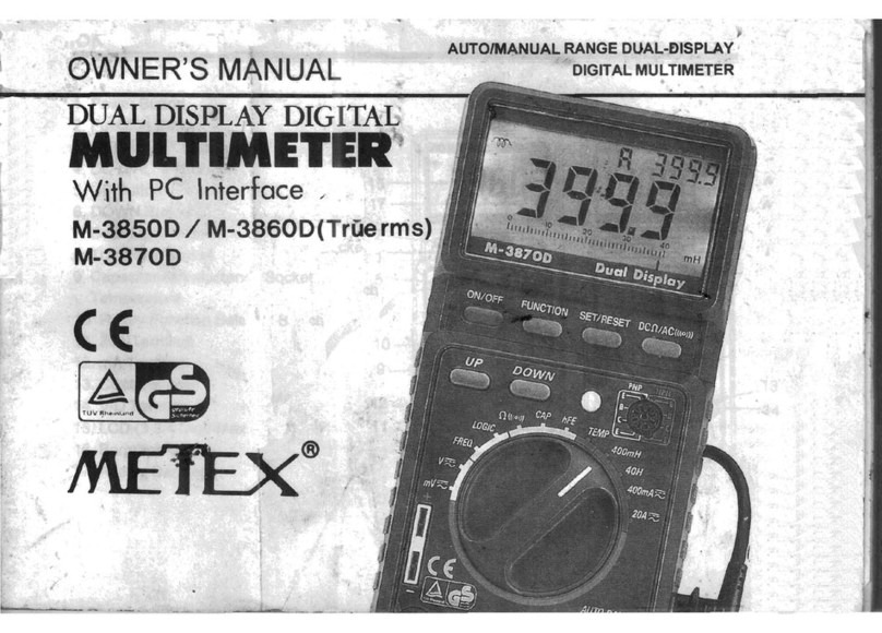
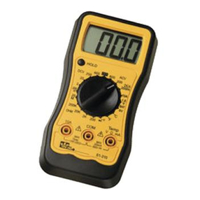
metex M-3800 User manual

m"
DIGTTAL
MULTIMETTR
OPERATING
MANUAL
lvl-3ElC)o

1.
2.
3.
il
$mFaniliarization
tlD,(3 |ń Digit; Max1999)
Porpr orr-off sr{itch
function/Range switch
TR soclret(Transistor hp
emeasurenent
only)
20A terninal
A terminal
0.t terminal
V/Q teroinat
Tilt starń(on
to haryiĘ or the rear case);rpvable by sqr:eezing
starńing posit'ion
llllllll
mNTENT
lllllltl
1.Introduction ..
2.Safety Information
2-1. Safety Requirements
f-2. Safety Symbols
2-3. Safety l{arnings
3.
Features
3-1. overload Irńication
3-2. low*Battery Irdicator
3-3. Other Feature
4.}basurirĘInstructions ....
4-7. Preliminary Notes
4-2. DCVoltage Measurement
4-3. AC Voltage Measurenent
4-4, E Cument Mreasurement
4-5. AC Current Measurement
4-6. Resistance}łleasurement
4-7, Diode I'teasurement
4-8. Ar-rdibleContinuity Test
44. Transistor hre l4easurement
5'}łaintenance... ,... 1.|
5-1. 9-volt Battery Replacenrent
5-2. Fuse Replacement
6.Specifications . .... 19
6-1. General Characteristics
6-2. Special Cbraracteristics
T.Warranty ... ZL
4
I
4.
5.
6.
7.
8.
9.
-z- -3-

1,
Intrdrrction
liith this Digital l.fultirneter, you have acquired a
high-quality, powerful performance, hearry-ituty nrgged
arń handheld m'l]'timeter that will give you confidence
arrl peace of mind in your every measuring job.
Please read these operating instructions very
carefully, before commencingyour measurement.
2.
Safety
Informtion
2-1. This neter has manufactured and tested in
acccrdance with It 348 ant DIN S'l4lL/WE C4l7,
Part 1: Safety Requirements for Electronic
l,leasuring Apparatus, Safety Class II.
Ihis manual
oontains information ań warnings
which mustbe observed to assr.re safe operation
ard naintain the reter in safe cordition.
Z-2. Safety Syrnbols
on the front panel warns that the input
voltage or current should not exceed ttle
values irdicated on the Ternrinal panel.
on the front panel fudicates that
dangerous voltages may exist at the
terminals.
€} for fuse replacemnt.
l-i1 for Battery replacement.
.- on the front pane] irńicates doub].e
llU insulation.
2-3. Safety l{arnings
f-3-1, To prevent electrical shocK haząr.d arrr1,or
damage to the meter, do not measure
voltages exceeding 1000V DC or 750V AC"
Z-3'2. To avoid damage to the meter aod/or rnlury
observe the input linits as stat'€rj
hereunder.
INPUT LIMITS
I'UNCTION TERI'IINAI.S INPUTI-I
1T DC v/ś) + ClM 1000v
DC
ńL. v/Q + cOM ;*;;;
Ovł{) + COM 250Vm
A DC,,AC A+COM 24rc
2OA E,/AC 204 + COM zCAm
tr- fr v/ś) + co|'J Z5OV DC
2-3-3. The 20A range is noi fuse-protected. To
avoid danage or injury, use the meter only
in circlits limited by fuse or
circuit-breaKer to 20A or 4000 VA.
MlTq i
--,--,1
:l I
--_---i
:l
-----l
lz'AC I
I
I
lI
l
:15
:5
r_T
,
-4- -5-

Do not apply voltage to between the A or Z0A
terninal and CtM terminal. This warning
assures protection against inlury and/or
damage
to the meter.
WHEN
I4AKING
CURRENTMEASUREMEMS, MAKESURE
T1{ATTl{E MIJLTIMETER
IS CONNECTM IN SER]ES
l.lITI{T}M LOAD IN IiHICH THE CURRENTIS TO BE
MEASURED.NEVER CONNEST 'I}tEMETER ACROSSA "
VOLTAGE
SOURCE.NEGLIGENCE TO DOSO, I{ILI
PESULT IN EITHER BLOWING THE OVERLOAD
PROTECI'ION FUSE OR DAMAGING TI{E DEVICE
UNDER TEST.
2-3-4. To avoid damage
to the meter, disconnect
test Leads from test points before changing
function.
f-3-5. To avoid electrical shock, be careful when
worKing above 60V DC or 25V AC. Such
voltages pose a shock hazard.
2-3-6. To avoid electrical shocK hazard. do not
touch test leads, tips or the circuit
under measurement while power is turned on.
f-3-1. Ensure the test Leads are in good condition.
f-3-8. Do not get the meter arrd test leads wet. . {,
thasunry
Instnrtions
4-1. Prelininary t{otes
4-1-1. Sometimes the last digit wj.ll not regj.ster
"0". This, however, will have no effect on
the measured value.
3.
Featlres
3-1. Oyerload Irdication
is displayed, when inpn 1s roo
excessive to display.
3-2. low Battery Irdicator
The E3 " synboL appears when the
battery voltage drops to certain limits. For
proper operation, replace the battery as
soon as possible. Continued use with a low
battery will lead abnornaL readings.
3-3. Other Features
3-3-1. 30-positions-rotary switch to select
function and range.
3-3-2. 17mnhiqh oontrast LLD.
3-3-3. Ruggedized case protected agai.nst an
externaL collision.
3-3-4. Hiqh surge voltaqe protection upto 3KV.
-6- -7-

4-1-2. The function switch must be set to the
range before commencing measurernent or
tes!.
4-2. DC Voltaqe llhasurenent
4-2-I. Connect the Black test lead to the COt'l
terminal and the Red test lead to the V/Q
terminal.
4-2-2. Set the function swj.tch to your desired
DC V range and connect the test leads
across the source or load under measurement
In case of negative voltage, " - " segrment
will appear on the left side of LCD.
See Fignrre 4-2.
4'2 DC
Voltage measurenent
Note: 1. If the 'roltage is unknown before
measurement,
set the functron switch
to the nightest range first and nove
down the ranges, steP bY steP.
2. lthen the "1" is displayd,the range ie
overloaded. The furction swit'ch nrugt b'€
set to a hi$ter range.
3. TaKe care to avoid mntact with
high tension circuits wtlen measurirry
high voltage.
4. Do not apply over 1000V DC / 700V AC to
the meter.
4-3. AC Yoltage lbasuremnt
4*3-1. Connect the Black test lead to tlt€ (S'l
terminal and the Red test lead to tle V/Q
terminal.
4-3-2. Set the function svłitc|r to your desired
AC V rarge ard @nnect the test Leads
across the source or load urder measurement
See Figre 4-3.
4-3 AC Voltage neasurenenL
Note: 1. See DCvoltage measuretnentNote 1
,2,3,4.
-9-

'1.'t. DC hrrrent t{easur€Bent
4-4-L. Connecr the Blaclr test lead to the COM
terminal and the Red to the A terminal for
a maxirnum
of 2A. For a maxirmrm
of 20A, npve
the Red test lead to ttre 20A tenninal.
4-4-f. Set the function switch to the DC A range
to be used and open circuit in which
oJrrent is to be measured. Connect the test
leads in series witi the load urder
rneasurement. See Fignre 4-4.
4-4-3. " - " sign for a negative current will
appear on the left side of the LCD.
Note: 1. See E voltage measurernent
Note 1, 2, 3.
2. The maximum inpt current is ZA or Z0A
deperdinE on the termina] used. Excessive
curent will blow the fuse, which must be
replaced. the Z0A range is not. protected
by the fuse. The fuse rating shoul"d not
be over 2A to prevent damage to the
internal" circuit.
3. Maxirun Voltage Drop (under full scale)
200!A-2A:300mV, 20A: 966pY
4. In case of neasuring Z0A, continuous
measurement over 15 ninutes may cause
damageto the meter.
5' I{HEN MAKING CURRENT MEASURWENTS, l'!ĄKE
SURE fi{AT 11{EMJLTIMETER IS CONNEMED
IN SERIES WITH T]{E LOAD IN IIHICHTHE
nJRREMT IS TO BE MEASURED.NEVER MNNECT
THE MŁTIMErER AcRoss A voLTAoE sCIncE'
TO M SO, CA}i RESULT IN EITI{ER BLOWING
N$ OVERLOAD PROTETTION zuSE OR
DAI4AGING TI{EDEVICE BETNGTESTED.
4-5. AC Current Measurement
4-5-I. Connect the Black test lead to tire COM
tenninal and the Red test lead to the A
terminal for a maxi"m"un
of A, Foi a
maxi:num
of 20A, npve the Red test lead to
the 204 terminal.
4-5-2. Set the function switch to your desired AC
A range and open circuii in which current
is to be measured. Connect the test leads
in series with the load under neasuremena.
See Fiqn:re 4-5. ..
* ll -
4-4 DCCurrent
neasurenent
*10-

4-5 AC CurrenL
neasurenent
Note: 1.See DCCurrent neasurenentNote 1,2,3,4,5.
4-6. Resistance lŁasuremnt
4-6-1. Connect the Blaclc test lead to the @tl
terminal ard the Red test lead to tt)e V/Q
terminal.
4-6-2. Set the function switch to your desired ohm
rarĘe ard connect the test, 1eads across
the resistance to be nreasured. See Figure
4-6.
,'
il
Note: 1.
4-6 Resistance neasurenent
If the resistance value beirg measured
exceeds the maxinum value of the range
selected, '' 1 ,. rłill be displayed for
irńicating overload. Se}ect a higher
range. For a resistance of approximately
1!łrhm
and above,the neter may talte a few
secorxls to stabilize. This is normal
for high resistance readings.
When the input is not loaded, i. e. at
open circuit, the " 1 " will be displayed
}ihen checkrng in-circuit resistance,
ensure that the circuit urder test has
all power off afi all capacitors are
fulJ.y discharged.
The resistance ranges of this instrument
are protected by a posistor above 500V
and a resistor network below 500V, except
200ohn range which is protected up to
250V onj.y. -13-
1
3.
.ł.
-tz-

Some devices nay be danaged by the
ctrrent applied durirry resistance
rpasurements. The following table sbows
the voltage ard ąrrrent available on
each range.
RAT.JGE AB
200c) 1.2 0.8 o.M
2KQ 1.2 0.3
zOKQ t-L o.42 0.06
zOOKQ r.2 0.43 0.07
2l'.tQ L.L 0.43 0.001
20t'rQ r.2 0.43 0.0001
A. is open circuit voltage at the terninals
B. is voltage across a resistance egual to
full scale value.
C. is c-trrent in milliamperes through a
shorted circuit at the input terminals.
* A1l values are tlpical.
4-7. Diode lłeasrrrerent
5.
4-7-t. Connect
terminal.
terminal.
the Black tesr lead to rhe COt'j
ard the Red test lead to the V/Q
-14-
4.7-2. Set the function switch to the " łł.ff
range ard connect the test leadg across thę
diode under measurernent" See Figure 4-?.
Note: 1. When the input is not loaded, i.e. at
open circuit, only "1" on the left side
of the LCD is displayed, i-ndicatjng
overload.
2. There is 1mA Current flow through the
device under test.
3. The meter displays the forward voltage
drop in mill-volts, ard overload when the
diode is reversed.
4. The polarity of the REDtest lead is ,,+,,"
4-8. Aulłihle Continuity Test
4-8-1. Connect the Black test lead to the COM
terminal and the Red test lead to tbe VlCf
terminal. -15-
4-7 Djode rłeasuremen!

4-8-z. set t}'e function switch to the +n rarĘe
(t}le sane range as diode) .'rń oonnect
test leads across the resistance urńer
nreasurernent. See Fignre 4-8.
4-8-3. The buzzer sourds if the resistance between
two leads is less than approxirnately
3Oohms.
4'8 Audible
continuitY Test
Note: 1. See Diode measurement
Note 1.
2. The circuit to be tested nust be in
power-off oorrlition whilst performing the
continuity test.
4Ą. Transistor hrg Test
44-1. Changethe function switcb to t}tehrp range
4-9-2. Deternine whether the transistor is NPN
or PNP ań locate the B[itter, Base arń
Collector Leads. lnsert the leads of the
transistor into the comect holes in the
socket on the front panel' s€e FiErre 4.9.
-16*
4-9-3. The neter will read the approximate hrr
vaLue at the test crcrxiition of base c'urrent
10lA Vcr 2.8V.
not use
4-9 Transistor hFE Test
5.l,lainternrrce
Your Digital !fultimeter is a precise eLectronic
device. Do not tanper with circuit.
To prevent electrical shock hazard, turn off the
meter and disconnect test leads before renrovi:lg
the back cover, for any adjustnentrl replacement,
maintenance or repair.
After completion of any adjustment, replacement,
maintenance or repair. if applyi-rrg
a voltage is
necessary, it must be carried out only by a
skilled person who is aware of the potential
hazard.
- Lt -

M AVOID DIIIIAGE; -
1. Never connect npre than 1000 Volt DC or 700
Volt AC.
2. Never crnnect a source of voltage with
function sbrirch in oHMPoSITIoN.
3. Never operate the DW, unless the back
case is in place and fully closed.
4. Battery or Fuse replacement should only
be done, after the test leads have been
disconnected and power is OFF.
5-1. 9 Volt Battery Replaceuent
tlhen the " E3 " appears on the LCD, pLease
replace the battery as soon as possible for
maintaining normal readings. The battery type
is NEDA1604 or 6Ff2 for 9 voltage.
5-2. Puse Replacement
If the fuse should be replaced, use only
ZA/?.5,0V, fast blow t)te fuse which should be
identical in physical size to the original or
the spare fuse in the storage compartment
inside of the meter.
-18- -tY-
6.Specifications
6-1. General Characteristicg
* .Max Display : 1999counts (3 X Diqit) with
automatic polarity j-rdication
t Input Im@ance : 10 l'lchm
' Max Input furrent of AC 6.m : 20A (l.{ax
15
mirutes )
* Reading Time : 2-3 readings per secord
" Operating Tenperature : 0C to 40C (32"F to
104"F)
* Storage Temperature : -10C to 50"C (14"F to
122"F)
" Tempenature for Guarant.eed Accuracy: +23C *.
5T
" Battery Tyep: pgptr
1604
9v or óF22 9V
" Size (H
x li x L. Cln)
: 3.6 x 8.8 x 17-2
" Net.i{eight : 34Ę + 1Ę (lncl. 9V Battery)
* Accessories sup'p1ię6
: Ęeratjrrg Manual, a
pair of test leads, spare fuse, 9V battery,
carrying case.

6-2 Special Characteristics
PUNCTION RANGE ACCURACY NESOLUT'
N
VOLTAGE
200nV
2V
zvv
20ov
I
000v
t0.5r of rdg + 1 dqt
100lv
lnV
1
OnV
1
0OnV
1V
AC
VOLTAGE
200nV + 7,Za of rdg + 3 dqt 100r'V
?v
20v
200v+0.8r of rdg + 3 dgt lnV
1
OnV
1
00nV
700
v+1.2x of rdg + 3 dgt
DC
CURRENT
2O0aA
2nA
20nA
+0.5x of rdS + 1 dgt o.ltA
7pA
lolA
200nA
2A łI.Zx of rdg + i dgt 1
00rA
l rDA
fol,
20uA tz.Ox of rdg + 5 dgt 10nA,
1OnA
AC
CURRNAT
200/lA
2nA
20nA +1.0x of rdg + 3 dgt 0.114
rpA
lotA
200m4
2A t1.8x of rdg'i 3 dgt 100pA
lnA
z0A,
20uA +3.0r of rdq + 7 dgt 1
0mA
1
OnA
KE.
SISTANCE
2000 +0.5t of rdg + 3 dgt 0.10
ZKO
20K0
200K0
2M0
i0.5t of rdg + I dgt 10
10Q
I
00Q
lK0
20tt0t 1.0x of rds +
2 dqt I
0K0
-
20-
IIARRAI{IT
l{arrants this instrurcnt to be free from defects in
materiaf ard worknanshipfor a period of one year.
Any instrunent fourń defective within one year froln
the delivery date ard returnd to the factory with
tranportation charges prepaid, riill be repaired,
adjusted, or replacd at no charge to the orig.inal
purchaser. This warranty does not cover expendable
itemssuch as batteries or fuses. If the defect has
beencaused by a misuse or ab,normal operat.ing
conditions, the repair will be billed at a noninal
cost.
Table of contents
Other metex Multimeter manuals
