metex M-4660A User manual
OPERATING INSTRUCTIONS
Digital-Multimeter
M-4660A
Item-No.: 12 37 30
NOTICE D´EMPLOI
Multimètre numérique
M-4660A
No de commande: 12 37 30
BEDIENUNGSANLEITUNG
Digitalmultimeter
M-4660A
Best.-Nr.: 12 37 30
GEBRUIKSAANWIJZING
Digitale Multimeter
M-4660A
Best.-Nr.: 12 37 30
NL
D
F
GB
Imprint
These operating instructions are published by Conrad Electronic GmbH, Klaus-
Conrad-Str. 1, 92240 Hirschau/Germany
No reproduction (including translation) is permitted in whole or part e.g.photo-
copy, microfilming or storage in electronic data processing equipment, without
the express written consent of the publisher.
The operating instructions reflect the current technical specifications at time of
print.We reserve the right to change the technical or physical specifications.
©
Copyright 1997 by Conrad Electronic GmbH. Printed in Germany.
Note de l´éditeur
Cette notice est une publication de la société Conrad Electronic GmbH, Klaus-
Conrad-Str. 1, 92240 Hirschau/Allemagne.
Tous droits réservés, y compris traduction. Toute reproduction, quel que soit le
type,par exemple photocopies,microfilms ou saisie dans des traitements de texte
electronique est soumise à une autorisation préalable écrite de l`éditeur.
Impression, même partielle, interdite.
Cette notice est conforme à la règlementation en vigueur lors de l´impression.
Donnéestechniques et conditionnementsoumisà modifications sans aucunpréalable.
©
Copyright 1997 par Conrad Electronic GmbH. Imprimé en Allemagne.
Impressum
Diese Bedienungsanleitung ist eine Publikation der Conrad Electronic GmbH.
Alle Rechte einschließlich Übersetzung vorbehalten. Reproduktionen jederArt,z.B.
Fotokopie, Mikroverfilmung, oder die Erfassung in elektronischen Datenverarbei-
tungsanlagen, bedürfen der schriftlichen Genehmigung des Herausgebers.
Nachdruck, auch auszugsweise, verboten.
Diese Bedienungsanleitung entspricht dem technischen Stand bei Drucklegung.
Änderung inTechnik undAusstattung vorbehalten.
©
Copyright 1997 by Conrad Electronic GmbH. Printed in Germany.
Impressum
Deze gebruiksaanwijzing is een publikatie van Conrad Electronic Ned BV.
Alle rechten, inclusief de vertaling, voorbehouden. Reprodukties van welke aard
dan ook, fotokopie, microfilm of opgeslagen in een geautomatiseerd gegevens-
bestand, alleen met schriftelijke toestemming van de uitgever.
Nadruk, ook in uittreksel, verboden.
Deze gebruiksaanwijzing voldoet aan de technische eisen bij het ter perse gaan.
Wijzigingen in techniek en uitrusting voorbehouden.
©
Copyright 1997 by Conrad Electronic Ned BV. Printed in Germany.
NL
D
F
GB
100% recy-
cling paper.
Bleached
without
chlorine.
100%
Recycling-
papier.
Chloorvrij
gebleekt.
100%
Recycling-
Papier.
Chlorfrei
gebleicht.
Page 2 - 34
Page 35 - 71
Seite 72 - 107
Pagina 108 - 143
*07-04/C

3
1. Introduction
This 4 1/2-digit multimeter with multi-display is equipped with several
special features which are useful fo some measurements:
With the key FUNC several special functions can be selected which are
supported by the buttons SET/R, UP and DOWN. These special functions
are shown in the top line of the display. The function D-H (= Data Hold)
for example, variable measuring values are "frozen" to use them after-
wards for further evaluation, e. g. measuring reports. The frozen value
can be read in the middle sub display.
With the next special function the meter will automatically record the
minimum (= MIN), the maximum and the average (AVG) display reading.
The neaxt special funtion is the relative mode REL, it enables the opera-
tor to compare a manually prset reference value with the subsequent
measurement.
The three subdisplays show from the left to the rigth the deviation in %,
the difference to the reference value and the preset reference value.
With the function "MEMORY" up to 10 display contents can be stored
and be recalled with the function RCL later from the memory.
The special function CMP (= Comparison) enables you to compare a refe-
rence value (High/Low) with the subsequent readings.
The function LOGIC, at the rotary function switch, enables you to check
and to display all usual logic levels. Besides he display reading Lo, ----
(= Pass) and Hi, the subdisplays show the frequency of the level and the
voltage.
With the function "hfe" small power transistors can be checked. The func-
tion CAP Hi and CAP Lo check the capacity of capacitors.
With the function "TEMP" you can measure temperatures to max +1200°C
with a thermoelement (option), it is connected to the CAP measuring
socket. With the frequency function "FREQ" you can measure the fre-
quency of measuring signals (not mains voltage) to 200 KHz. With the
function "S/O" = Signal Out, 10 different preset frequencies from 10 Hz
to 10.24 KHz can be recalled. For this a special adapter (option) is needed
which is connected to the CAP-measuring socket.
2
Digital Multimeter M-4660A,
Order-No. 12 37 30
Attention! Read before operation!
Read these operating instructions carefully and completely. In the case
of damage caused by ignoring the instruction, the claims under gua-
rantee lapse. No legal liability can be accepted for any damage from the
multimeter being used for the wrong purpose or operated improperly.
Thus cannot take any liability for consequential damage.
The proper operation of the measuring unit includes:
• measurement of DC voltage to 1000 VDC max in five steps
• measurement of AC voltge to 750 VAC max in five steps
•measurement of DC and AC currents to 20 A max., for max. 30 s (un-
fused), in 3 steps each
• measurement of resistance to 20 mΩ, in 6 steps
• measurement of capacity to max. 20 µF in 2 steps: Hi and Lo
•continuity test, diode, transistor and logic test, measurement of fre-
quencies to max. 200 KHz, signal output of 10 Hz to 10,24 KHz and
teperature measurement of -40°C to +1200°C
Contents page
1. Introduction . . . . . . . . . . . . . . . . . . . . . . . . . . . . . . . . . . . . . . . . . .3
2. Safety rules . . . . . . . . . . . . . . . . . . . . . . . . . . . . . . . . . . . . . . . . . . .4
3. Description of the control elements . . . . . . . . . . . . . . . . . . . . . . . .6
4. Use of the multimeter . . . . . . . . . . . . . . . . . . . . . . . . . . . . . . . . . .9
5. Measurement . . . . . . . . . . . . . . . . . . . . . . . . . . . . . . . . . . . . . . . .18
6. Maintenance and calibration . . . . . . . . . . . . . . . . . . . . . . . . . . . .31
7. Technical data and accuracy . . . . . . . . . . . . . . . . . . . . . . . . . . . . .31
GB

5
cuits. If adjustment, repair or maintenance to the measuring unit must
proceed to the unit open, it must only be carried out by qualified ser-
vice personnel or qualified electricians/engineers, familiar with the
dangers and the relevant rules (VDE 0100, VDE-0701, VDE-0683).
•Capacitors in the unit may still carry voltage, even if the unit has been
separated from all power voltage sources and measuring circuits.
•Please ensure to use new fuses of the proper current rating and the
specified type. Do not use repaired fuses and do not bridge the fuse
holders. When replacing the fuse separate the measuring unit from the
measuring circuit, remove any input signal and switch it off. Remove all
connected cables and probe tips ! Use a suitable crosspoint screw driver
and carefully open the case. Remove the faulty fuse(s) and replace it
with a new one of the same type and nominal current 0.8 A quick blow,
250 V; usual name: F 0.8 A/250 V or F 800 mA/250V. For the amperage
range 15 A ultra rapid, 250 V.
After the fuse has been exchanged close the cabinet. Do not operate
the unit before it has been closed and screwed safely.
• Take special care when working with voltage above 25 V (AC) and
above 35 V (DC). Even such voltage might cause a life-dangerous elec-
trical shock when electrical conductors are touched.
First switch off voltage source, connect the measuring unit with the
terminals of the voltage source to be measured, set the measuring unit
to the necessary voltage range and afterwards switch on voltage source.
After measurement has been finished, switch off the voltage source
and remove the measuring cables from the terminals of the voltage
source.
•Make sure before each voltage measurement the unit is not set to the
amperage range.
•Before changing the measuring range remove the probe tips from the
object to be measured.
•Control before each measurement the measuring unit and your test
leads to make sure they are not damaged.
4
It is also possible to connect the DMM with a respective cable (option)
which is connected to the built-in interface to a personal computer. After
installation of the respective software on the PC a communication bet-
ween the multimeter and the PC is possible.
2. Safety Rules
•The digital multimeter M-4660A is CE-tested and meets the EMC gui-
deline: 89/336/EWG.
•This unit is constructed and checked according to DIN 57 411 Part 1/
VDE 0411 Part 1, Safety Requirement for Electronic Measuring Units
and IEC 1010-1. This unit left the factory in a technically safe and per-
fect condition. To maintain this condition and to guarantee safe ope-
ration, the user must observe the safety rules and warnings (Attention)
contained in these operating instructions, by all means.
•This multimeter must only be used in fuse lines which are protected
with 16 A. The voltage existing/appearing must not exceed 250 VDC/
VACrms and the maximum load must not exceed 4000 VA. It is not allo-
wed to use the unit for installations in the overload range III according
to IEC 664. The unit and the measuring cables are not protected
against arcing (IEC 1010-2-031, section 13.101).
• Keep children away from measuring units!
•Observe the accident prevention measures in the workplace prescibed
by the Associations of Employer’s Liability Insurance for electrical plant
and operating material.
•When using the unit in schools, training centers and hobby-workshops
the use of the measuring equipment must be responsibly supervised by
teachers or trained personnel.
•If covers are opened or parts are removed, except it is possible without
tools, voltage-carrying components may be accessable. Terminals can
also carry voltage. If it is necessary to open the unit before adjustment,
maintenance, repair or exchange of parts or modules, the measuring
unit has to be disconnected from all voltage sources and measuring cir-

7
2. Push button "FUNC" for special function (see 4.3.2 and 4.3.4)
3. Push button "SET/R"
To set/reset the special functions.
4. Push button "UP" additional button to set the special functions (see
4.3.2 and 4.3.4)
5. Push button "DOWN" additional button to set the special functions
(see 4.3.2 and 4.3.4)
6. SOCKET for capacitance measurement (capacitors), for temperature
measurement "TEMP" and for signal output "S/O".
7. Transistor Socket
This socket is for testing the hfe-parameter of low power transistors.
8. Rotary Function Switch
To select the different modes (voltage and current measurement,
etc.) and measuring ranges
9. 20-A Input Socket
This input socket is fused with 15 A and is designed for measuring DC
and AC current to max. 20 A (max. 30 s with 15 min. interruption bet-
ween the measurements).
10. mA-input
This socket is for measuring DC and AC current to 200 mA max. (fused
with 800 mA quick blow)
11. COM (-) -Input Socket (COM or Minus Terminal)
12. V/Ω-(+)-Input Socket (Plus Terminal)
13. Multifunction Liquid Crystal Display (LCD) (4 1/2digit, max. display
value 19999) with three 4 1/2subdisplays.
14. Analogous Bargraph
15. Bargraph-Segments
6
• To avoid an electrical shock, don't touch directly or indirectly the test
probes and the test points during measurement.
•Do not use this measuring unit in environments or rooms with adverse
environmental conditions where combustible gases, vapors or dusts
exist or may exist. For your own safety avoid under all circumstances
that the measuring unit or the test leads become damp or wet.
Avoid the usage near
a) strong magnetic fields (loudspeakers, magnets)
b)electromagnetic fields (transformers, motors, coils, relays, contactors,
electromagnets etc. )
c) electrostatic fields (charge/discharge).
d)transmission antennas or hf-generators
•If there are doubts whether a risk-free use is still possible the unit has
to be put out of operation and be secured against unintentional use.
It must be assumed that a risk-free operation is no longer possible if
- the unit shows visible damage
- the unit does not work and
- longterm storage under adverse conditions or
- stress during transport took place
•Don't switch on the measuring unit immediately after transferring it
from a cold to warm room. Condensed water might impair or destroy
your unit. Give the unit time to warm up to room temperature before
you switch it on.
3. Description of the Control Elements
Picture (fold-out page)
1. Power ON/OFF (see also 4.3.2)
With this push-button the measuring unit is turned on and off. A
short time after turning the unit on it is ready for operation.

9
30. hFE This symbol indicates the transistor test.
31.1., 2. and 3. Sub-Display
These three small sub-displays with 4 1/2digits are activated during
the different function modes.
32 = Low Battery
When this symbol is displayed, it is time to change the battery
33. Different Units of the Display Values
4. Use of the Multimeter
4.1 Inserting the Battery - Battery Exchange
To guarantee precise measurement, insert a standard 9 V battery. If the
battery symbol appears in the display, it is time to change the battery.
Proceed as follows:
• disconnect your measuring unit from the measuring circuit
•disconnect the test-leads from the measuring unit and turn off the
power.
•remove with a crosspoint screw driver the fastening screw to open the
battery compartment.
• now lift the cover carefully.
•separate the old battery from the battery snap and fasten a new one
of the same type.
•after the battery has been changed reinsert the battery into the batte-
ry case and close it carefully
• secure it with the screw.
•be careful that the battery leads (red/black) are not pinched between
the housing and the cover.
+-
8
16. Overload "OL"-Indication
"OL" is displayed and an acoustic signal is emitted when the range is
exceeded = overflow (no acoustic signal during resistance measure-
ment, diode test or temperature measurement).
Attention!
Observe the max. input limits.
17. Data Hold D-H
Data Hold means the meter will "freeze" a display reading.
18. A-H "Auto-Hold" = Min, Max and AVG holding with simultaneous
display
19. REL = Relative = Reference Value
20. MEM = Memory = to memorize the value
21. RCL = Recall = to get back the memorized reading on the display.
22. CMP = Comparison = Compare a Reading
23. Reference No. (0 to 9)
24. / = Diode Test and acoustic continuity check
25. AC = Symbol for AC current or voltage
26. " - " = Minus Sign or Symbol for Negative Polarity
27. FREQ = Frequency
this symbol is displayed in the frequency count mode
28. TEMP = Temperature
This symbol is displayed during temperature measurement.
29. CAP = Capacitance
CAP is for Capacitance => Measurement of capacitors

11
tional function. Even without additional functions "small" displays (sub-
displays) support measurement.
To select such additional function press the key FUNC (2). Press it again
to scroll through the different sub-functions.
To exit the menu press SET/Rest-key twice: to operate the SET/Rest-key
press once to enter, press button twice to exit/reset (depending on the
preset sub-function)
4.3.2 Terminal and Switch Imprint
a) Press the ON/OFF-key (1) to turn the unit on and off: Press the key
once to turn the power on, press it again to turn the DMM off.
AUTO-POWER-CUT-OFF extends the life of the battery by turning off
the meter: if neither the rotary function switch nor a button is ope-
rated for 12 minutes the DMM is automatically turned off. During
"communication" of the multimeter with a PC, i.e exchange of data,
AUTO-POWER-OFF is disabled.
b) FUNC
Press this button to select the function modes. The following symbols
appear in the display when you scroll in the function modes:
D-H -> A-H -> REL -> MEM -> RCL -> CMP
c) SET/R (= Set / Reset)
Press this button once to activate or to enter the selected function
mode. Press this key only once.
-Press the function mode the button D-H again to return to basic set-
ting (press until the beeper sounds).
-In the function mode A-H (MIN-MAX and AVG) the A-H symbol is dis-
played. After the first push of the SET/R key the A-H symbol is set and
will stop blinking. If the SET/R-key is pressed again, the R-H symbol is
fixed. You can commence measurement. Another push of the SET/R
key discards the function and the previous normal mode is restored.
-In the function modes REL, MEM, RCL and CMP push SET/R button
several times to return to normal mode. Another possibility to exit
from these modes is either to press the button FUNC or ON/OFF once
or to move the rotary function switch to an adjacent position (observe
all safety rules!).
10
Attention!
Never use the measuring unit before the cover has been closed comple-
tely, to avoid an electrical shock!
Never leave empty batteries in the measuring unit, as even corrosion-
free batteries might leak and chemicals could be released, which are
detrimental to your health and disturb the battery compartment.
Please remember batteries - due to their heavy metal content - are no
ordinary refuse. They must be disposed of in special containers (collec-
ting points) or in a safe manner that complies with all applicable laws.
4.2 Connection of the Measuring Cables
For measurement use only the test-leads which are supplied with your
measuring unit. Only these are admissible. Ensure the connection plugs
and test probes are in good condition before use, pay attention that the
insulation is undamaged.
These test-leads are rated for max. 1000 V. The maximum rating of the
multimeter M-4660A is 1000 VDC max or 750 VACrms. Use special caution
when working with voltage above 25 V AC and above 35 V DC.
Attention!
To avoid the risk of electrical shock, instrument damage and/or equip-
ment damage, input limits must not be exceeded.
4.3 Operation
4.3.1 Basic Settings
Hint
The numbers which are put in brackets in the following text refer to
"Description of the control elements", point 3.
Press the button "ON" (1). Turn the rotary function switch to the desired
position. Now the meter is ready for "normal" operation without addi-

13
the risk of instrument damage and danger to life if there are voltages
exceeding 25 VAC or 35 VDC.
The different basic measuring ranges are selectable by turning the
switch:
DCV = DC voltage (blue, 5 ranges)
ACV = AC voltage (red, 5 ranges)
ACA = AC ampere (red, 3 ranges)
DCA = DC ampere (yellow 3 ranges
hFE = transistor test (grey, 1 range)
LOGIC = logic measurement (grey, 1 range)
CAP = capacitance measurement (grey, 2 ranges)
FREQ = frequency measurement (grey, 1 range)
TEMP = temperature measurement (yellow, 1 range)
S/O = Signal-Out (red, "1" range)
/= diode test/acoustic continuity test (blue, 1 range)
Ohm = resistance measurement (blue, 6 ranges)
d) 20-A-Input Socket
For DC- and AC-current measurements to max. ! 20 A. Insert the Red
test-lead into the input socket.
Attention!
During current measurement the rotary function switch must never be
set to voltage measurement (mV or V).
e) mA-Measuring Socket
For measurements to 400 mA max.!, connect the red test-lead, pay
attention that the rotary function switch is set to position 4 mA" or
"400 mA".
f) COM = Common Input Terminal
For all measurements, except capacity and transistor measurement or
"S/O" function, the black test-lead must be connected. (common-ter-
minal means minus or "-" or earthing jack)
12
d) UP/DOWN
Press UP or Down button to determine the reference value in the fun-
ction modes REL or CMP or to address the stored value (reference
numbers) in the subfunctions MEM or RCL (recall memory).
4.3.3 Terminal and Switch Imprint
a) Transistor Socket hfe
The eight pole transistor terminal is lettered symmetrically with (E)
Emitter,(B) Base, (C) Collector. Insert the transistor pins into the tran-
sistor socket as in the drawing according to transistor type, remove
voltage before measurement.
b) Capacity- and Temperature Measuring Socket (poles "+" and "-") and
signal output S/O.
In this socket discharged capacitors can be checked, observe correct
polarity. Make sure the connector pins are long enough to avoid
unreliable measurement .
For temperature measurement plug in type "K" temp probes (NiCrNi)
in the marked sockets, observe the correct polarity. To receive an out-
put signal connect the respective adapter with the CAP-socket.
Attention!
The outer contacts are only for capacitance measurement, the inner con-
tacts are only! for temperature measurement. Never confuse the sockets
to avoid damage to the meter. Pay attention to the following picture:
c) Rotary Function Switch = Measuring Function Switch (8)
Attention!
Never turn the rotary function switch during measurement, as there is
temperature
measurement
+
-
-
+capacitance
measurement

15
e) REL (= Relative)
The relative mode enables the operator to compare the reference
value with a subsequent reading. Proceed as follows:
- Set the function mode at REL mode and press once the button SET/R
-Store the polarity by pressing the UP and DOWN keys, afterward press
SET/R button.
-Press UP and DOWN buttons again to set the desired reference value.
Press SET/R by turns to move to the next digit.
-For final setting of the reference value press SET/R button once again.
-The meter will now display the difference between the stored refe-
rence value and the subsequent readings on the sub-displays, while
the present (true) measurement is on the main-display. The left sub-
display will show the difference in %, the middle sub-display will
show the offset and the right sub-display the preset reference.
To exit this function mode press SET/R again or press FUNC or turn the
rotary function switch (observe the safety rules!), afterwards return
to normal settings.
f) MEM (= Memory)
Up to 10 measurements (reference number 0 to 9) can be stored and
recalled. Proceed as follows:
1. Push function button until MEM flashes in the display, afterwards
press the key SET/R once. MEM is fixed and the reference number flas-
hes. Make your measurements and push the SET/R key once to store
the present measurement value in the first free memory location =
reference no. 0.
2. Press UP/DOWN button to go to the next free memory location (refe-
rence no. between 0 and 9).
Make again your measurement and push the key SET/R once. This sel-
ected memory now is addressed. If a memory number which has been
used before is selcted, the previous value is updated and stored with
the new measurement value.To exit this function mode turn the fun-
ction switch (observe the safety rules!) or press the buttons FUNC or
SET/R.
14
g) V/Ω-Socket
For measurement of voltage, frequency, resistance, continuity, diodes
and logic tests plug in the red test-lead in this terminal.
4.3.4 Display Explanation and Symbols
a) Digital Display
Digital readings are displayed the main- and the sub-displays (small
displays) on a 19999-count basis with automatic polarity indication (-),
(for negative voltage or reversed polarity). There are four decimal
point positions.
b) Analogous Bargraph
The bargraph consists of 43 segments and is faster than the digital
display. It functions like the needle of an analogous measuring instru-
ment, but without its mechanical disadvantages. Is is especially for
quick changing measuring signal, for which the digital display is too
"slow". So you can quickly see tendencies in the measuring values.
If the measuring range is exceeded "OL" for Overload is displayed the
bargraph is flashing and a warning sound sound is emitted (no acou-
stic signal during measurement of resistance, diode, temperature -
"OL" without thermo-element).
c) Data-Hold "D-H"
In this mode you can freeze a reading in the second ("small") display
by pressing the SET/R button. To exit this subfunction hold down
SET/R button or FUNC for a few seconds or turn the function selector
switch (observe the safety rules). Afterwards you return to the basic
setting.
d) Auto Hold A-H
In this function the meter will automatically record the minimum and
the maximum display reading, MIN and MAX values. These values are
currently updated = refreshed. The MIN-value is shown on the left
sub-display, the MAX-value on the right sub-display. On the middle
sub-display the average value = AVG is shown. This value is currently
"refreshed".
To exit this function mode press SET/R again or press FUNC or turn the
rotary function switch (observe the safety rules!), afterwards return
to normal settings.

17
has been entered (as far as a manual selection is possible) Comparison
= CMP is activated.
To exit CMP mode turn the rotary function switch (observe the safety
rules!) to an adjacent range or press "FUNC". Reset with the SET/R
button is also possible, even during measurement.
4.4.5 Display Annunciators and Symbols for the Modes
a) Diode Test and Continuity Check
The value displayed is the forward voltage at approx. 1 mA test current.
Range of 0 - 2.0 V.
The contnuity test enables you to check continuity of wiring, connec-
tions or fuses. Either acoustic or visual test (display of measurement)
is possible. An acoustic signal is emitted at resistors below 30 Ω.
b) Negative Polarity
Shows if test-leads are confused or indicates negative input with a " - "
before the measurement.
c) FREQ Frequency Measurement
You can measure frequency up to 200 kHz.
d) TEMP Temperature Measurement
You can measure temperatures from -40°C to +1200°C with a thermo-
elemet (NiCrNi).
e) CAP Capacitance Measurement
The capacitance ranges lets you measure discharged capacitors of 10 nF
to 20 uF.
f) hFE Transistor Test
Enables you to measure the hFE value.
g) rDY = ready = Logictest
This function enables you to check and to display all usual logic levels.
h) Low Battery
A 9-Volt alkaline battery in this meter has an avery life of approx. 100
to 150 hours. Low battery indication approx. 8 hours before battery is
"dead". Battery check between the measurements.
16
Hint
If you exit the function mode because you pushed the SET/R button too
often, this function mode is left, but the memory is not erased and can
be "recalled" with the following function mode.
g) RCL (= Recall)
This function enables you to get the memorized reading back on the
LCD. Follow these steps:
-Push FUNC key until RCL flashes. Push SET/R once. RCL is fixed but the
reference number flashes. Press UP or DOWN buttons to address the
desired number where the measurement has been memorized. Press
SET/R button to get the memorized value back on the display. Then
the chosen value will appear on the left sub-display. The following
memory locations are displayed in the other smaller displays. To exit
this function mode turn the function switch (observe the safety rules!)
or press the buttons FUNC or SET/R, afterwards return to basic set-
tings.
h) CMP (= Comparison)
This function mode enables you to make the High/Low comparison of
subsequent readings, by comparing a reading with both the stored
high reference value and the stored low reference value.
On the sub-display "Lo" appears for reading less than the low refe-
rence value, "Hi" is displayed for reading more than the highest refe-
rence value and "Pass" for a middle value between the low and the
high reference value.At the same time an interval signal is emitted.
To activate this function mode, push "FUNC" until the symbol "CMP
appears on the top of the display and "LOW" flashes over the left
sub-display. Now push again SET/R button and then "UP" and
"DOWN" to set the minimum reference value with polarity. Press
after each change SET/R button again, to enter the setting and to go
to the next digit. As soon as the minimum reference (MIN) value has
been fixed, "HIGH" flashes over the right sub-display. Set this high
reference value respectively (with polarity and four digit value). After
the reference values have been defined press SET/R key again. Now
"R-H" for Range Hold flashes in the top line of the display. Set with
the UP and DOWN buttons the measuring range (e.g. voltage control
in a circuit under worst-case conditions). After the measuring range
19
3. Connect the test-lead tips with the object to be measured (load, cir-
cuit etc).
4. The respective polarity of the value is displayed together with the cur-
rent measuring value in the main display.
Each of the five voltage ranges presents an input impedance of 10 mΩ
(in parellel with < 20 pF). AC-voltage input is AC-coupled.
As soon as " - " is set before the value during DC voltage measurement,
the voltage is negative (or the test leads are confused).
Hint
Due to the sensitive nature of the input terminal your meter might dis-
play any small values (not connected with the object). This residual
value will not affect the actual measurements. It will vanish as soon as
you start measurement. But Auto-Power-Off is not active when the
"phantom-measurements" are displayed.
During DC voltage measurement the three sub-displays below the main
display are active.
In the left sub-display the measuring value appears 1 second later, in the
middle sub-display the measuring value appears 2 seconds later and in
the right sub-display the measuring value appears 3 seconds later.
During AC voltage measurement the middle sub-display will show the
frequency of the AC voltage (in the range of 40 Hz - 400 Hz)
~V
18
i) The following symbols indicate the unit of the value displays:
AC = AC current or voltage
DC = DC current or voltage
mV = Millivolt (exp.-3)
V = Volts
mA = Milliampere (exp.-3)
A = Ampere
Hz = Hertz
kHz = kilohertz (exp.3)
MHz = Megahertz (exp.6)
°C = Centigrade Degree
µF = Microfarad (exp.-6)
nF = Nanofarad (exp.-9)
pF = Pikofarad (exp.-12)
KΩ= Kiloohm (exp.3)
MΩ= Megaohm (exp.6)
dB = Decibels
5. Measurement
5.1 Voltage Measurement
Attention!
Never exceed the maximum input limits. of max. 1000 VDC or 750 VACrms.
Do not touch circuits or parts of circuits, if you measure voltage more
than 25 VACrms or 35 VDC.
If you measure voltage the aperage terminals must not be connected.
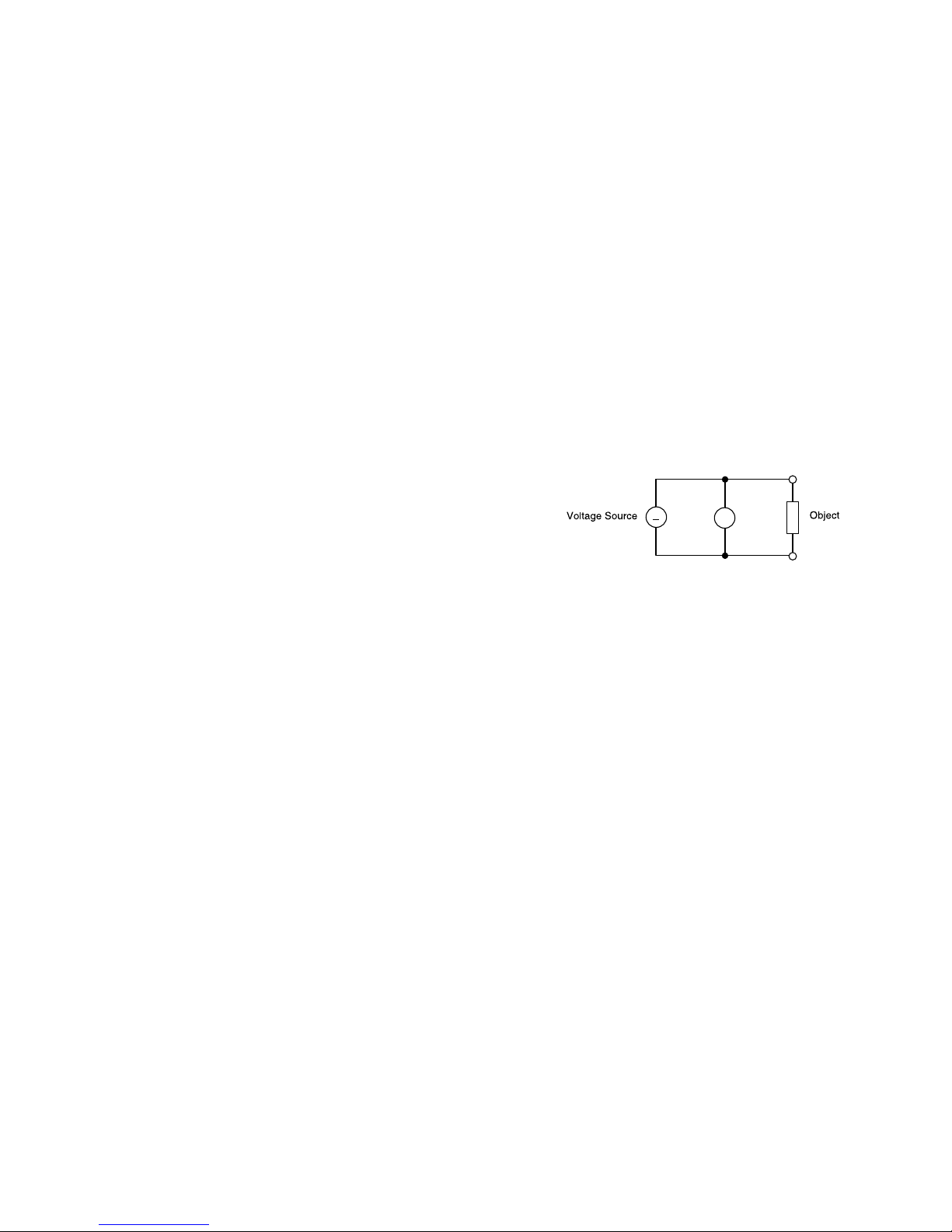
To measure DC or AC voltage proceed as follows:
1. Connect the red test-lead with the V/Ωsocket (12) and the black test-
lead with the COM-socket (11).
2. Set the rotary function switch to the desired position (range). You
have 5 ranges for dc voltage ( DCV) or AC voltage (ACV) measurement
each. During AC voltage measurement the right sub-display will show
the dB-value of the AC voltage, the middle sub-display the frequency
and the main display the present measuring value.
21
Attention!
Never measure currents in circuits in which voltages over 250 VDC/
VACrms could exist, this is life dangerous! Never measure currents
exceeding 20 A.
Only measure in circuits which are fused with 16 A or in which powers
exceeding 4000 VA could not exist. Current measurements of 20 A may
not last longer than 30 seconds and may only be executed in intervals
of 15 minutes.
Hint!
During AC current measurement the middle sub-display will show the
frequency of the AC voltage (in the range of 40 Hz to 400 Hz) and the
main display shows the present measurement.
During DC current measurement the three sub-displays below the main-
display are active. In the left sub-display the present reading is taken
1 second later, the middle display the reading is taken 2 seconds later
and in the right display the reading appears 3 seconds later.
When measuring current never connect the voltage terminal and the
measuring socket.
5.3 Continuity Test
With this function you can test dead leads, fuses, circuits.
Proceed as follows :
1. Connect the black test-lead with the COM-socket (11) and the red
test-lead with the V/Ωsocket (12).
2. Set the rotary function switch to /(= continuity test or diode
test). Afterwards connect the test-lead tips to the object to be mea-
sured (all voltage must be removed).
3. If the line resistance is less than 40 Ωa test buzzer sound is emitted.
Attention!
Never measure capacitors which carry voltage, as a possible discharge
could destroy your measuring unit.
20
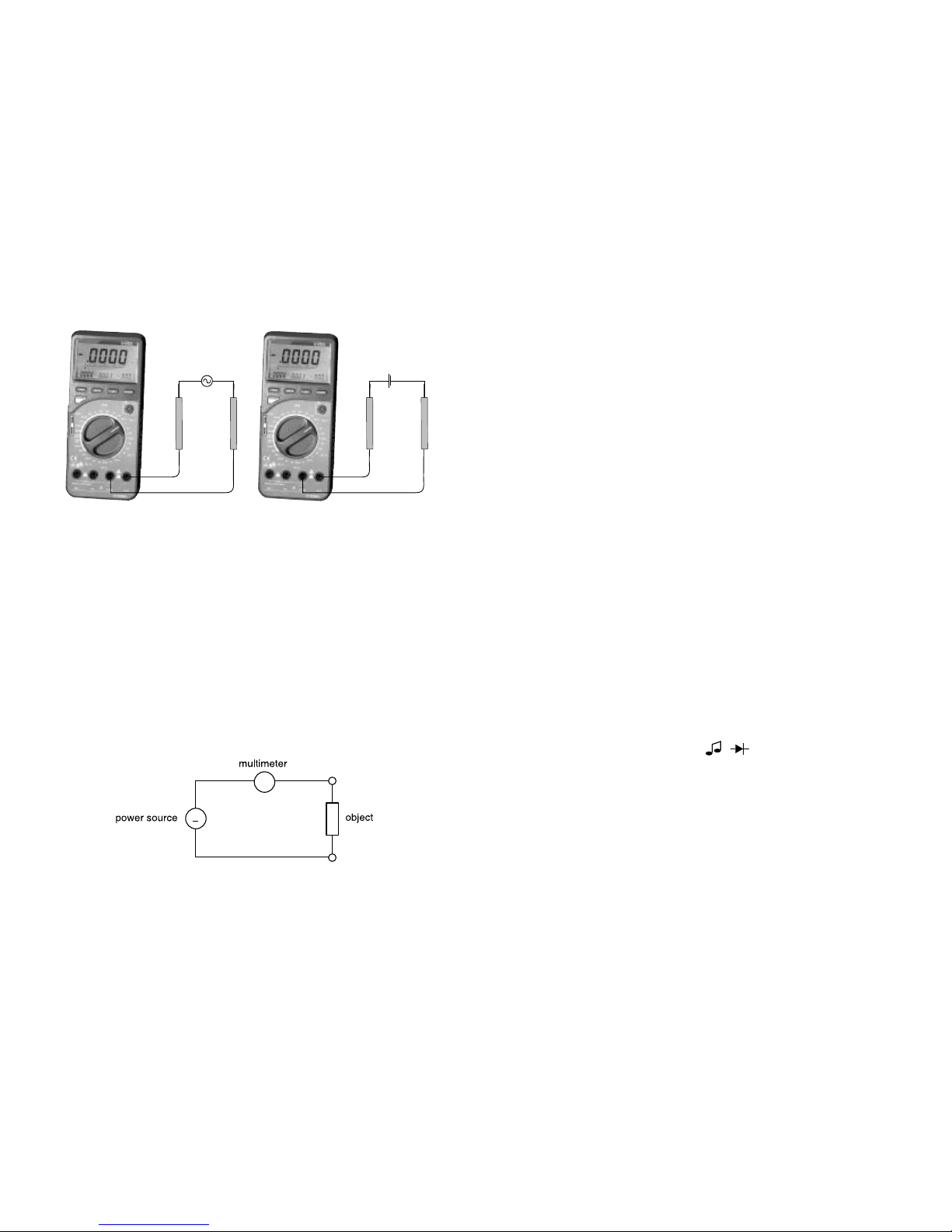
5.2 Current Measurement
Follow these steps to measure DC or AC current:
1. Connect the black test-lead with the COM-socket (11) and the red
test-lead with the mA-socket (10), if you want to measure current to
200 mA max. and with the 20-A-Socket (9), if you want to measure
current over 200 mA to 20 A max.
2. Select with the rotary function switch the ampere position (DCA or
ACA).
3. Connect the test-leads in series with the circuit or load. (See following
drawing).
~
A

23
or similar, etc. This might seriously influence the measuring result.
If resistance over 1 MΩis measured, the display might need a few
seconds to stabilize.
During resistance measurement the three sub-displays below the main-
display are active. In the left sub-display the present reading is taken
1 second later, the middle display the reading is taken 2 seconds later
and in the right display the reading appears 3 seconds later.
5.5 Capacitance Measurement
Follow these steps to measure capacitance:
Set the rotary function switchto CAP (Lo) or CAP (Hi) and insert the
discharged capacitor into the appropriate socket observe the correct
polarity ("+" and "-"). If the are relatively low capacities as 100 pF or
smaller it better to use the special function "REL" (described under 4.4.3 c)
to set the display to "0000". In the other ranges (200 n or 20 u) wait a
few seconds until the off-set sets the display to "0000".
Attention!
When shorting capacitors (discharge), high-energy discharge may take
place. Caution life danger! Do not touch the terminals if there are capa-
citors with voltages over 35 VDC or 25 VAC. Use special caution in envi-
ronments or rooms with adverse environmental conditions where
flammable gases, vapour or dusts exist or may exist ==> explosion
hazard!
During capacitance measurement the three sub-displays below the
main-display are active. In the left sub-display the present reading is
taken 1 second later, the middle display the reading is taken 2 seconds
later and in the right display the reading appears 3 seconds later.
During capacitance measurement the voltage and the current terminals
and the transistor socket must not be connected.
+
-
22
During continuity check the measuring socket and the current sockets
must not be connected.
5.4 Resistance Measurement
Attention!
Make sure all objects, circuits and components under test are without
voltage! During continuity check the voltage measuring socket and the
current sockets must not be connected.
Proceed as follows:
1. Connect the black test-lead with the COM-socket (11) and the red
test-lead with the V/Ωsocket (12).
2. Set the rotary function switch to resistance measurement Ohm.
Connect both test-lead tips to check the continuity of the test-leads.
3. Now connect the test-lead to the device you want to measure.
Hint
During resistance test, make sure that the contact between probes and
circuit is good. Make sure the test points are free of dirt, oil or solder flux
25
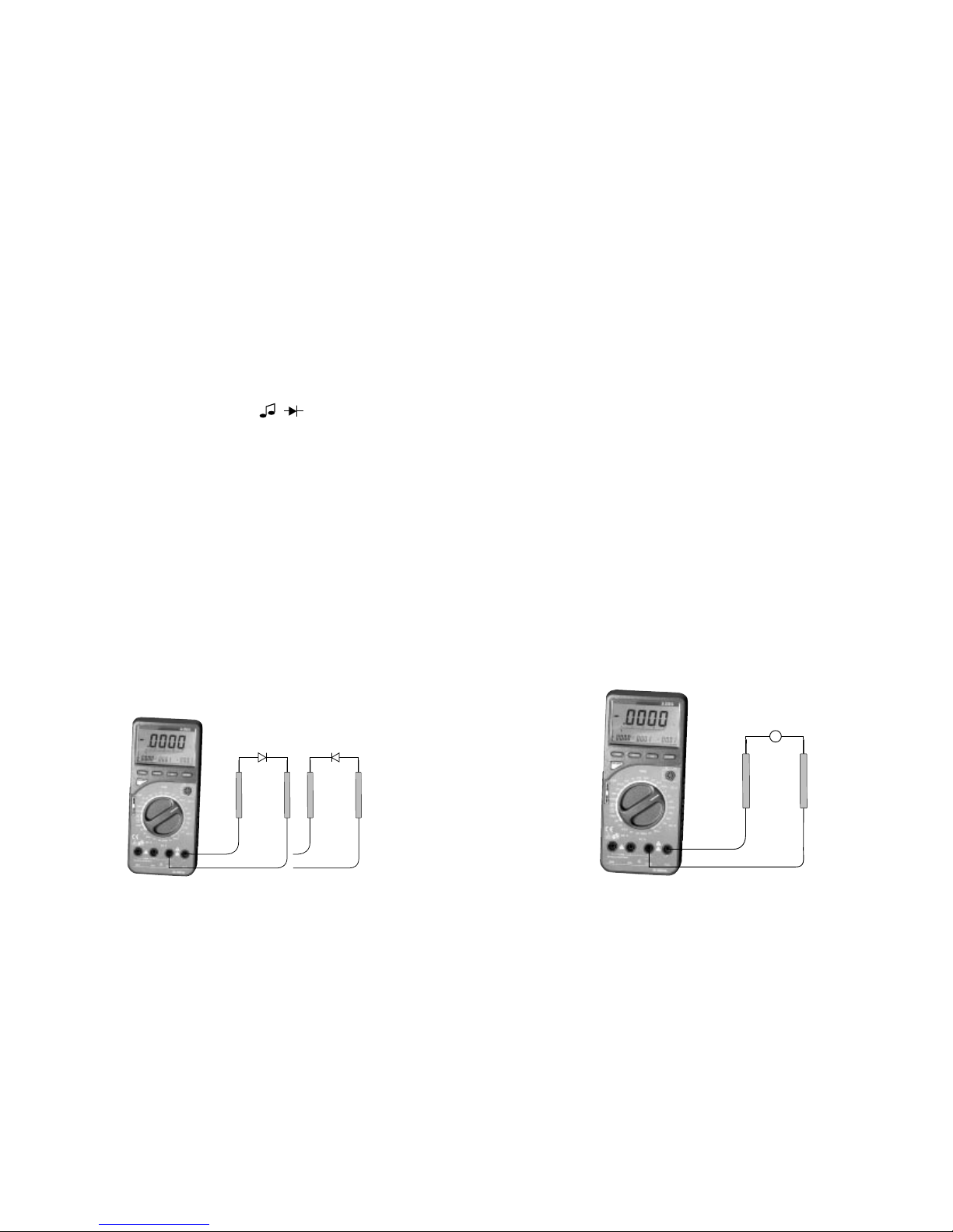
5.7 Frequency Measurement
Follow these steps to measure frequency:
1. Connect the black test-lead with the COM-socket (11) and the red tst-
lead with the V/Ωsocket (12).
2. Set the rotary function switch (7) to "FREQ" and connect the test-lead
tips with the frequency source (generator, etc.).
Attention!
Observe the max. input limits. Never connect voltages over 50 VDC/
VACrms (rms = eff). It is life dangerous to touch the terminals or probe
tips when measuring voltages over 25 VAC or 35 VDC.
Disconnect the test-leads from the contact points before changing the
meter function and range. The sensitive electronic of the measuring unit
might be destroyed and you expose yourself to severe shock hazard.
If there are voltages below 50 mVrms (at 1 Khz) no frequency measure-
ment is possible.
During continuity check the voltage measuring socket and the current
sockets must not be connected.
During frequency measurement the right sub-display shows dB-value of
AC voltage, the middle sub- display the AC voltage "V".
~
~
~
24
5.6 Diode Test
To test diodes proceed as follows:
1. Connect the lack test lead with the COM-socket (11) and the red test-
lead with the V/Ω-socket (12).
2. Setthemeasuringfunctionswitch to " /". No connect the test-lead
tips with the object under measurement to an off-circuit semiconduc-
tor line, the RED probe-tip to the anode, the BLACK test-lead tip to
the cathode (as a rule it is marked with a coloured ring, point etc.)
If you check a diode's forward voltage, you will measure voltage of
approx. 0.25 V (Germanium) or 0.7 V (Silicium) to 2.5 (or 250 mV, 700 mV
to 2500 mV), if the diode is not defective. The middle sub-display will
show 9ood for "good".
If you reverse the probe-tips, this means red to the cathode and black
to the anode, you check the so called reverse direction.
If "OL" is displayed and "Open" in the middle sub-display, the diode
is good. However, if any voltage is displayed, you connected the
object wrong or the diode is defective.
Attention!
During diode test, observe that the diode or the circuit in which it is
built in, must be without voltage. All existing capacities must be
discharged. During continuity check the measuring socket and the cur-
rent terminals not be connected.
Forward Direction Reverse Direction

27
During hfe-paramenter measurement of small power transistors the
three sub-displays below the main-display are active. In the left sub-dis-
play the present reading is taken 1 second later, the middle display the
reading is taken 2 seconds later and in the right display the reading
appears 3 seconds later.
5.9 Logic Test
This measuring function lets you easily check logic levels in digital circuits
(5 V or 12 V or 18 V logic etc.).
The multimeter will display one of the three modes:
•if the high level at the test point exceeds 70 % of Vcc (or V++ or Vc or
V+ etc.) "Hi" is displayed (to max. 18 VDC, above "OL" for "Overload"
is displayed).
• if the test point shows a low-level falls below 30 % of Vcc, "Lo" is dis-
played.
•if the level at the test-point is between 30 % and 70 % of Vcc, "----" is
displayed.
To check the logic level and to set the level rans proceed as follows:
1. Switch on your measuring unit.
2. Set the rotary switch to "LOGIC". This function displays "rdY" (=
ready for measurement).
3. Connect the test-leads with the COM-input socket (black lead) and
the V-Ωsocket (red lead).
4. Now connect the other end of the black test-lead to the "ground"
point of the digital circuit = "-" (normally).
5. While keeping the black test-lead connected to the ground touch
with the red test-probe to the supplying voltage point Vcc (or V++ or
V+ or Vc etc.) If the supply voltage is below 20 VDC and you confirm
once the button "SET/R", a buzzer sound is emitted and "Hi" is dis-
played.
26
5.8 Transistor Test
Attention!
The transistor jack is not protected against overload. During continuity
check the voltage measuring socket and the current sockets must not be
connected.
To measure the hFe-parameter (of amplification) of a transistor follow
these steps:
1. Set the rotary function switch to hFE position.
2. Insert the transistor you want to measure into the appropriate transi-
stor socket.
Pay attention to the following points:
Hints
•observe the sequence of connection of the transistor (e.g. C-B-E) (you
will find it in the transistor comparative table).
•Sometypes of transistors contain internal base-to-emitter resistance
which could cause undependable measuring results.
•The hFE-measuring value is no absolute measurement. It only indicates
if the transistor is operating or not. The true amplification of a transi-
stor depends on its operating current. This multimeter supplies a base
current up to 10 uA at a Uce of 2.8, the collector current is measured
to calculate the respective hFE-value.
•It is not possible to measure transistors which are connected in a circuit.
•It is not possible to measure the hFE-value of FETs or other unipolar
transistors.
•If a transistor (e.g. BD 242 etc.) has too large terminals for the test
socket, do not force it into the test socket, as it could be damaged.
•The hFE-measurement is affected by temperature differences As soon
as you touch the transistor when you plug it in the socket and warm it
with you fingers the measuring result could be influenced. If the hFE
reading is not stable, take the transistor out and let it come to room
temperature.

29
5.11 Usage of the Analogous Bargraph
The bargraph is easy to use and to understand. Is is comparable with the
needle of an analogous measuring instrument, but without its mechani-
cal disadvantages. Is is especially for quick changing measuring signals,
for which the digital display is too "slow". So you can quickly recognize
see tendencies in the measuring values. The measuring rate is 3-4 mea-
surements/s.
5.12 CMOS Signal Output
The mulitmeter M-4660A is equipped with a kind of "Function Generator"
which supplies ten preset frequencies with a voltage of max. 3.3 V. To
"tap off" the signal insert the enclosed signal adapter into the capacitor
socket, observe the correct polarity. The other end of the adaptor has
two small alligator clips.
To change the multimeter into a signal generator and to select the output
frequency follow these steps:
1. Select S/O with the rotary function switch.
2. Connect the enclosed signal adapter (on one end with alligator clips)
with the capacity measuring socket of the multimeter.
3. Turn on the multimeter.
4. In the basic function mode the reference number is displayed in the
left sub-display, the main display will show the respective frequency
"0.010 KHz" (= 10 Hz). In the middle sub-display the respective signal
output voltage is displayed in "V"(0.0).
5. To select other output frequencies push either "UP" or "DOWN" button.
For frequency and connected reference number see below:
0.010 KHz = 10 Hz, reference no. 0
0.050 KHz = 50 Hz, reference no. 1
0.060 KHz = 60 Hz, reference no. 2
0.100 KHz = 100 Hz, reference no. 3
0.400 KHz = 400 Hz, reference no. 4
1.010 KHz = 1010 Hz, reference no. 5
2.021 KHz = 2021 Hz, reference no. 6
4.042 KHz = 4042 Hz, reference no. 7
8.084 KHz = 8084 Hz, reference no. 8
10.24 KHz = 10240 Hz, reference no. 9
28
Attention!
If this supply voltage is more than 20 VDC, a buzzer sound is emitted,
too and "OL" for Overload is displayed.
During logic measurement the measuring socket and the current termi-
nals must not be connected.
6. Now the multimeter is "ready" to check the logic level test points of the
circuit in question. Separate the red test-probe from the supplying
voltage point. Now move the red test-pobes to the points in question.
Hint
During logic-level measurement, the right sub-display will show the pre-
sent DC current value and the middle sub-display displays the frequency.
5.10 Temperature Measurement
Temperature is displayed on the main and the sub-display. The main display
will show the temperature in Centigrade, while the middle sub-display
will show the temperature in Fahrenheit. The temperature range is from
-40°C to + 1200°C. Temperature measurement is exclusivley executed
with K-type temp probes.
For temperature measurement proceed as follows:
1. Select "TEMP" with the rotary function switch.
2. Plug in the temp probe into TEMP/CAP socket, observe the correct
polarity (narrow and wide tongue). (Use both sockets before and
after the separation bar in the middle)
Attention!
Do not connect voltages. The unit can be destroyed. When measuring
temperature, do not connect voltage input terminal or the current ter-
minals.

31
Communication Specifications for Data-Transfer:
Transfer Rate . . .: 1200 Baud
Character Code . .: 7-bit ASCII
Parity . . . . . . . . .: None
Stop Bits . . . . . . .: 2
6. Maintenance and Calibration
Calibrate the meter once a year to maintain its accuracy over a longer
period of time. Fuse replacement is described in point 2. (Safety Rules).
Battery replacement is described in point 4.1.
Clean the unit and the display with a clean, lint-free, antistatic, dry, cloth.
Attention!
When cleaning the housing, do not use detergents containing hydrog-
carbons, petrol, alcohol or similar. These chemicals could damage the
surface of the measuring unit. Besides solvent vapors are dangerous to
your health and explosive.
7. Technical Data and Accuracy
7.1 Technical Data
Display . . . . . . . . . . . . . . . .: 41/2-digit liquid cystal display (LCD),
maximum reading 19999 with automatic
polarity display
Max. Measuring Rate . . . . .: 2.5 measurements per second
Max. Input Current DC/AC .: 20 A
Operating Temperature . . .: 0° to +40°C
Storage Temperature . . . . .: -10°C to +50°C
Relative Humidity . . . . . . . .: 0° to 90 % (0° to 35°C)
0° to 70 % (35°C to 50°C)
Temperature Coefficient
for Guaranteed Accuracy . .: +23°C ± 5 K (= Kelvin)
30
Attention!
Never short the output of the signal generator, as the output terminal
and the meter could be destroyed. When the function "Signal-Out S/O"
is selected neither the voltage input terminal nor the current sockets
must be connected.
5.13 Usage of the Mulitmeter in connection with a
Personal Computer
a) Connection
Connect the enclosed RS-232 cable between the meter's RS-232
connector and the PC serial port, switch off your computer before
(see figure).
Now turn on your multimeter and your computer
b) The data format consists of a frame of 14 bytes. The frames are set
as follows:
BYTE 1 2 3 4 5 6 7 8 9 A B C D E
Example 1) DC - 3 . 9 9 9 V CR
Example 2) 3 . 9 9 9 Mo h m CR
O 1O 20 30 4O W

33
Mode Accuracy Resolution
Measuring
Range
measuring voltage at the open circuit: < 1,2 V
time display needs to stabilize: 2 MΩapprox.
5s
20 MΩapprox.
15s
Resistance 200 Ω+/-(0,2%+10dgts) 0,01 Ω
Capacitance 2000 pF +/-(2%+20dgts) 1
pF
Frequency 20 KHz +/-(2%+5dgts) 1 Hz
200 KHz -"- 10 Hz
+/-(3%+50dgts)
+/-(3%+20dgts)
Diodentest
buzzer sound for resistance
< 30 Ω, 2.8 VDC max.
input sensitivity: > 50 mVrms (rms = effektiv)
max. input sensitivity: 250 VDC/VACrms
Temperature -40°C bis +200°C
transistor test range: hFE 0 - 1000
basis current: approx. 10 µA
VCE (UCE):
max. 2.8 V
+200°C bis +1200°C
test current: 1.0 mA max.
measuring voltage: 2.8 VDC max.
20 µF +/-(3%+30dgts) 1 nF
200 nF -"- 10 pF
20
MΩ+/-(0,5%+5dgts) 1KΩ
2 KΩ+/-(0,15%+3dgts) 0,1 Ω
20 KΩ-"- 1 Ω
200 KΩ-"- 10 Ω
2
MΩ-"- 100 Ω
Hint:
At measurement exceeding 20VDC/VACrms
the middle small display shows "OL".
32
Battery Type . . . . . . . . . . . .: NEDA 1604 9V or 6F22 9V, alkaline
Weight . . . . . . . . . . . . . . . .: 350 g (without battery)
Dimensions (L x W x H) . . .: 187 x 87 x 34 mm
7.2 Accuracy
• Accuracies are +/- (% of reading = rdg + number of digit(s) = dgt(s)).
•Accuracy is specified at 23°C +/-5°C with a relative humidity of below
75 %.
• Warm-up time is 1 minute.
Mode
DC 200 mV +/-(0,05%+3dgts) 10 µV
Voltage 2 V ———”——— 100 µV
20 V ———”——— 1 mV
200 V ———”——— 10 mV
1000 V +/-(0,1%+5dgts) 100 mV
AC 200 mV +/-(0,5%+10dgts) 10 µV
Voltage 2 V ———”——— 100 µV
20 V ———”——— 1 mV
200 V ———”——— 10 mV
750 V +/-(0,8%+10dgts) 100 mV
valid at a frequency of 40 Hz to 60 Hz
above there is an additional deviation of 0,25 %
DC Current 2 mA +/-(0,3%+3dgts) 100 nA
200 mA +/-(0,5%+3dgts) 10 µA
20 A +/-(0,8%+5dgts) 1
mA
AC Current 2 mA +/-(0,8%+10dgts) 100 nA
200 mA +/-(1,0%+10dgts) 10 uA
20 A +/-(1,2%+15dgts) 1
mA
Frequency Range and additional error see AC current
Measuring
Range Accuracy Resolution
0.1°C
0.1°C

35
Multimètre numérique M-4660A
Nº de commande 12 37 30
Important ! A lire impérativement !
Lisez cette notice attentivement. Tout dégât causé par le non respect de
ce mode d’emploi annule automatiquement le droit de recours à la
garantie. Nous n’assumons aucune responsabilité quant aux dommages
secondaires.
Le cahier des charges de cet appareil répond aux critères suivants :
• Mesure de tensions continues jusque max. 1000 VDC en 5 niveaux
• Mesure de tensions alternatives jusque max. 750 VAC en 5 niveaux
•Mesure de courants continus et alternatifs jusque max. 20 A, pendant
max. 30 sec (non protégé), chacun en 3 niveaux
• Mesure de résistances jusque max. 20 MΩen 6 niveaux
• Mesure de capacités jusque max. 20 µF en 2 niveaux : Hi et Lo
•
Test de continuité, de diodes et de transistors, test de logique, mesure
de fréquences jusque max. 200 kHz, sortie de signauxde 10 Hz jusque
10,24 kHz et mesure de températures de −40 °C jusque +1200 °C.
Table des matières Page
1. Introduction . . . . . . . . . . . . . . . . . . . . . . . . . . . . . . . . . . . . . . . .36
2. Consignes de sécurité . . . . . . . . . . . . . . . . . . . . . . . . . . . . . . . . .37
3. Description des organes de commande . . . . . . . . . . . . . . . . . . .40
4. Utilisation du multimètre . . . . . . . . . . . . . . . . . . . . . . . . . . . . . .43
5. Mesures . . . . . . . . . . . . . . . . . . . . . . . . . . . . . . . . . . . . . . . . . . . .53
6. Entretien et calibrage . . . . . . . . . . . . . . . . . . . . . . . . . . . . . . . . .67
7. Données techniques et tolérances de mesure . . . . . . . . . . . . . .68
F
34
7.3 Max. Input Limits
Voltage Measurement . . .: 1000 VDC or 750 VACrms
Current Measurement . . .: 20 A DC/AC A-range, max. 30 s with cool-off
time of at least 15 minutes max. 250 VDC/
VACrms
overload protection: ultra rapid 15 A 250 V
fuse (dim. 6 x 30 mm)
200 mA AC/DC in the mA range, max. 250
VDC/VACrms
overload protection: rapid 0,8 A-250 V-fuse
(dim. 5 x 20 mm)
Resistance Measurement .: 20 MΩoverload protection: 250 V DC/ACrms
Frequency Measurement .: 200 KHz with max. 250 V DC/ACrms input
voltage
Logic Test . . . . . . . . . . . . .: overload protection 250 VDC/AC
Attention!
The measuring modes transistor test, capacitance and temperature
measurement are not protected against overload or too high input vol-
tages.
Exceeding of the max. input limits will damage the measuring unit and
endanger the life of the user.

37
En plus, ce multimètre numérique peut être relié à un PC au moyen d’un
câble approprié (disponible en option), connecté à l’interface se trou-
vant sur le coté droit de l’appareil. Après l’installation du software
approprié, le PC peut entrer en communication avec le multimètre
numérique.
L’écran à cristaux liquides (LCD) à quatre chiffres et demi permet des
résolutions allant jusque quatre chiffres après la virgule. Une fonction
Auto-Power-Cut-Off empêche une consommation inutile des piles, le
multimètre s’éteint après plus ou moins 15 minutes de „non utilisation“
(càd un affichage fixe) en mode service.
Ce M-4660A est d’un usage universel, il peut être utilisé dans le domai-
ne des loisirs aussi bien qu’à l’école ou dans l’industrie (sous certaines
conditions).
2. Consignes de sécurité
•La compatibilité électromagnétique de ce multimètre a été vérifiée, il
satisfait la directive 89/336/CEE.
•Cet appareil de mesure a été construit et testé conformément aux
normes DIN 57 411 Partie 1 et VDE 0411 Partie 1, Mesures de protec-
tion pour les appareils de mesure électroniques. Il a quitté nos ateliers
en parfait état de fonctionnement. Pour ne pas compromettre cet
état et pour garantir un fonctionnement sans danger, il importe que
l’utilisateur se conforme aux consignes de sécurité et aux avertisse-
ments repris dans le présent mode d’emploi.
•Ce multimètre ne peut être utilisé que dans des circuits de courant
eux-mêmes protégés par un fusible de 16 A ou, dans lesquels,les ten-
sions ne sont jamais supérieures à 250 VDC/VACrms et la puissance
développée ne peut jamais dépasser 4000 VA
Cet appareil ne peut pas être utilisé dans des installations de la caté-
gorie III de surtension définie par IEC 664. Ni l’appareil, ni les câbles
de mesure ne sont protégés contre les arcs électriques (IEC 1010-2-031
Paragraphe 13.101).
• Conservez cet appareil hors de la portée des enfants !
•Dans le cadre d’activités à caractère commercial, l’usage du multimèt-
re ne peut se faire qu’en conformité avec la réglementation profes-
36
1. Introduction
Ce multimètre à quatre chiffres et demi, à écrans multiples est doté de
plusieurs fonctions auxiliaires qui complètent utilement les autres fonc-
tions de mesure :
La touche FUNC, combinée aux touches SET/R, UP et DOWN, permet
d’accéder à plusieurs fonctions spéciales. Celles-ci sont représentées dans
la partie supérieure de l’écran. Par exemple, la fonction D-H (= Data
Hold) permet de geler des valeurs mesurées variables afin de pouvoir
ensuite les inscrire pour une utilisation ultérieure, comme par exemple,
un protocole de mesure. La valeur mesurée gelée est visible dans le sous
écran du milieu.
La fonction spéciale suivante A-H (= Auto-Hold) mémorise automatique-
ment la plus petite valeur mesurée rencontrée (= MIN), la plus grande
valeur mesurée rencontrée (= MAX) et la valeur moyenne (= AVG). La
fonction spéciale suivante REL (= Relatif = valeur de référence) permet
d’abord d’introduire manuellement la valeur de référence et ensuite de
comparer celle-ci avec la mesure instantanée. Dans les trois sous écrans,
apparaissent, de gauche à droite, la déviation en %, la différence par
rapport à la valeur de référence et la valeur de référence choisie. La fon-
ction spéciale MEM (= Memory = mémoire) permet d’enregistrer jusque
10 valeurs mesurées, la fonction suivante RCL (= Recall = rappeler) per-
mettant de lire ces mémoires. Grâce à la fonction CMP ( = Comparison =
comparaison), vous pouvez introduire deux valeurs de consignes (LOW et
HIGH) qui seront alors comparées à la mesure courante.
Grâce à la fonction LOGIC sur le sélecteur rotatif, vous pouvez mesurer
différents niveaux logiques pour lesquels, en plus de l’indication Lo, ----
(= Pass) et Hi, vous seront données, dans les sous écrans, la fréquence du
niveau et la grandeur de la tension. La fonction „hFE“ permet de tester
les transistors de faible puissance. Les fonctions CAP Hi et CAP Lo per-
mettent de vérifier la capacité de condensateurs. La fonction „TEMP“
permet de mesurer, au moyen d’un capteur approprié (disponible en
option), raccordé à la borne de mesure CAP, des températures jusque
maximum +1200°C. La fonction „FREQ“ permet de mesurer des fréquen-
ces de signaux (pas à la tension du réseau) jusque 200 kHz. La fonction
„S/O“ = Signal Out permet, grâce à un adaptateur approprié (disponible
en option), d’obtenir 10 différentes fréquences fixes allant de 10 Hz à
10,24 kHz.

39
le calibre de mesure adéquat et rebranchez finalement la source de
tension.
Après la mesure, coupez la source de tension et retirez les câbles de
mesure des raccords de la source de tension.
•Assurez-vous, avant chaque mesure de tensions, que votre appareil ne
se trouve pas en mode de mesure de courants.
• Avant chaque changement du calibre de mesure, écartez de l’objet à
mesurer les pointes des sondes de l’appareil.
• Avant chaque mesure, vérifiez que ni votre appareil de mesure, ni ses
câbles ne sont endommagés.
•N’utilisez pour vos mesures que les câbles de mesure fournis avec
l’appareil. Seuls ceux-ci sont homologués.
•Pour éviter tout choc électrique lors de la mesure, évitez de toucher
directement ou indirectement les pointes de mesure et les parties
conductrices du circuit à mesurer.
•La tension entre la borne V/Ohm de l’appareil de mesure et la terre
ne peut pas dépasser 500 VDC/VACeff.
•Ne travaillez pas avec votre appareil de mesure dans des endroits ou
des environnements où se trouvent ou pourraient se trouver des gaz,
des vapeurs ou des poussières inflammables. Pour votre propre sécu-
rité, évitez que l’appareil de mesure et ses câbles ne soient humides
ou mouillés. Evitez d’utiliser cet appareil au voisinage direct :
a) de champs magnétiques puissants (haut-parleurs, aimants),
b) de champs électromagnétiques (transformateurs, moteurs, bobi-
nes, relais, vannes, électroaimants, etc.),
c) de champs électrostatiques (dé/chargement) ,
d) d’antennes émettrices ou de générateurs HF.
•Lorsque vous supposez que l’utilisation de l’appareil ne peut plus se
faire sans danger, mettez celui-ci hors service et veillez à empêcher
toute utilisation involontaire. Il faut supposer que l’appareil est hors
d’usage quand :
- l’appareil présente des dégâts apparents,
- l’appareil ne fonctionne plus,
- il a subi un stockage prolongé dans des conditions défavorables ou
- il a subi de mauvaises conditions de transport.
38
sionnelle en vigueur pour l’outillage et les installations électriques
des corps de métiers concernés.
• L’emploi de cet appareil dans une école, dans un centre de formation,
dans un atelier ou lors d’un hobby, doit être supervisé par le person-
nel d’encadrement qualifié.
•Lors de l’ouverture du couvercle ou lorsque vous ôtez une pièce, à
l’exception de celles prévues pour être enlevées à la main, vous pou-
vez donner accès à des pièces ou des raccords sous tension. Certaines
bornes de connexion peuvent également être sous tension. Lorsque
l’ouverture de l’appareil est nécessaire pour le réglage, l’entretien, la
réparation ou le remplacement d’une pièce, veuillez débrancher le
multimètre du circuit à mesurer et couper toute source de tension. Si
le réglage, l’entretien, la réparation nécessitent l’ouverture de l’ap-
pareil sous tension, confiez seulement ce travail à un spécialiste infor-
mé des dangers encourus et respectueux des règles de sécurité (VDE-
0100, VDE-0701 et VDE-0683).
•Les condensateurs se trouvant dans l’appareil peuvent encore être
chargés même lorsque celui-ci est coupé de toute source de tension
ou du circuit à mesurer.
• Vérifiez, lors de l’échange des fusibles, qu’ils sont bien du même type
et de capacité identique aux fusibles à remplacer. L’usage de fusibles
déjà réparés ou le pontage du porte fusible sont strictement interdits.
Pour effectuer l’échange de fusibles, débranchez l’appareil de mesu-
re du circuit à mesurer et éteignez-le. Eloignez toutes les lignes et
pointes de mesures. Prenez un tournevis en croix adéquat et ouvrez
ensuite le boîtier avec précaution. Retirez le(s) fusible(s) défectueux
et remplacez le(s) par un(des) fusible(s) du même type et d’intensité
nominale de courant égale à 0,8A flink, 250V; appellation usuelle :
F0,8A/250V ou F 800mA/250V pour le calibre A et à 15A super-flink,
250V.
Après avoir remplacé le(s) fusible(s), refermez et revissez le boîtier
soigneusement en sens contraire.
Ne réutilisez l’appareil que si celui-ci est bien refermé et revissé.
•Soyez particulièrement prudent en présence de tensions alternatives
supérieures à 25 V(AC) ou de tensions continues supérieures à
35 V(DC). Ces valeurs sont suffisantes pour provoquer un choc électri-
que dangereux en cas de contact direct avec les parties conductrices.
Coupez donc d’abord la source de tension du circuit à mesurer, effec-
tuez ensuite les connexions hors tension, puis choisissez sur l’appareil
Table of contents
Languages:
Other metex Multimeter manuals


