MetOcean Telematics NOVATECH iBCN User manual

NOVATECH iBCN
User Manual
Iridium / GPS Satellite Beacon
Document No.: TD 13-053
Model No. 1: MMI-513-00000
Model No. 2: MMI-613-00000
Release Date: 17-Apr-2017
Version No: 2.0
™


iBCN – User Manual
TD 13 – 053
1
Table of Contents
COPYRIGHT INFORMATION ........................................................4
1. SAFETY INFORMATION........................................................6
1.1 PRESSURE CASE ..............................................................................6
1.2 OUTDOOR USE ONLY......................................................................7
2. INTRODUCTION......................................................................8
3. QUICK START .......................................................................10
4INSTALLATION .................................................................... 11
4.1 ALTERNATIVE POWER OPTIONS...............................................11
4.2 ANTENNA ...................................................................................... 12
4.3 PRESSURE CASE ...........................................................................12
5OPERATING INSTRUCTIONS ...........................................13
5.1 ON/OFF.........................................................................................13
5.2 BATTERIES.................................................................................... 13
5.3 TEST OPERATION ........................................................................ 14
6OPERATION ..........................................................................15
6.1 OPERATING NOTES......................................................................18
6.2 CONFIGURATION .......................................................................... 19
6.3 IRIDIUM SATELLITE COMMUNICATION ....................................22
6.4 BLUETOOTH®COMMUNICATION ............................................ 23
6.5 CONFIGURATOR SOFTWARE TOOL ........................................... 26
6.6 TRANSMISSION DATA FORMAT .................................................28
7. MAINTENANCE .................................................................... 30
7.1 REGULAR MAINTENANCE........................................................... 30
7.2 BATTERY CHANGE....................................................................... 30
7.3 IBCN-7 BATTERY CHANGE........................................................ 33
7.4 “O” RING FACTS........................................................................... 34
7.5 “O” RING MAINTENANCE...........................................................35
7.6 CORROSION PREVENTION .......................................................... 36

iBCN – User Manual
TD 13 – 053
2
8. LICENSING REQUIREMENTS............................................ 37
9. WARRANTY...........................................................................38
9.1 WARRANTY TERMS..................................................................... 38
9.2 SERVICE TERMS ........................................................................... 39
10. SPECIFICATIONS .................................................................40
10.1 IBCN-OEM SPECIFICATIONS ...............................................43
10.2 IBCN DIMENSIONS.................................................................44
10.3 IBCN INFINITY DIMENSIONS................................................ 45
10.4 IBCN-3 DIMENSIONS ............................................................ 46
10.5 IBCN-7 DIMENSIONS ............................................................ 47
10.6 IBCN-RH-E DIMENSIONS .................................................... 48
10.7 IBCN-RH2-BP-CK DIMENSIONS ....................................... 49
11. INDEX .................................................................................50

iBCN – User Manual
TD 13 – 053
3
List of Images
Figure 1: Magnet Placement on Head Assembly .......................13
Figure 2: iBCN Activation Sequence ............................................... 17
Figure 3: Adding a Bluetooth Device.............................................. 23
Figure 4: Select Pairing Code Option..............................................24
Figure 5: Enter Pairing Code.............................................................. 24
Figure 6: Bluetooth Connection Established...............................25
Figure 7: Pairing Complete with COM port assigned...............25
Figure 8: Configurator Software Tool ............................................26
Figure 9: Configuration Dialog..........................................................27
Figure 10: Bottom End Caps Removed For Battery Change.31
Figure 11: iBCN-OEM Specifications...............................................43
Figure 12: iBCN – Iridium Beacon, 7500m ..................................44
Figure 13: iBCN Infinity – Iridium Beacon 12000m ................45
Figure 14: iBCN-3 – Iridium Beacon, 7500m ..............................46
Figure 15: iBCN-7 – Iridium Beacon, 7500m ..............................47
Figure 16: iBCN-RH – Iridium Beacon, 7500m...........................48
Figure 17: iBCN-RH2-BP-CK – Iridium Beacon Adapter ........49
List of Tables
Table 1: MMI Power Configurations............................................... 12
Table 2: Multiple Position Report Packet Format..................... 28
Table 3: T_POSITION_REPORT Data Format............................... 29
Table 4: Battery Options......................................................................30
Table 5: O-Ring Index ...........................................................................36
iBCN – User Manual
TD 13 – 053
4
Copyright Information
© Copyright 2017 – MetOcean Telematics
All Rights Reserved. The user manual must not be
reproduced, distributed, or transmitted in any form or by
any means, including photocopying, recording, or other
electronic or mechanical methods, without the prior
written permission of MetOcean Telematics.
PCB Integration User manual applies to the following
models:
Model Number Description
MMI-513-00000
Iridium Beacon, 7500m
MMI-613-00000
Iridium Beacon, 12000m
Information contained in this manual is subject to
regular updates and changes.
MetOcean Telematics has patents, patent applications,
trademarks, copyrights or other intellectual property
rights covering subject matter in this document. Except
as expressly provided in any written license agreement
from MetOcean Telematics; the furnishing of this
document does not give the user any license to these
patents, trademarks, copyrights or other intellectual
property.

iBCN – User Manual
TD 13 – 053
5
Copyright Information [Contd.]
© Copyright 2017 – MetOcean Telematics
Unauthorized duplication of any recordings whether
downloaded from internet or made from audio CDs is a
violation of copyright laws. The making of unauthorized
copies of copy-protected material, including computer
programmes, files, broadcasts and sound recordings,
may be an infringement of copyrights and constitute
criminal offence. This equipment should not be used for
such purposes.

iBCN – User Manual
TD 13 – 053
6
1. Safety Information
1.1 Pressure Case
As with any sealed pressure case, the contents could be
under pressure due to a battery or seal failure. This could
expel the batteries when either end cap of the case is
removed.
To be safe, always point the end being opened away from
you during opening. The end caps are designed to vent
internal pressure as they are being removed.
If venting is heard during end cap removal, stop removal
until venting has stopped.
If a battery is trapped in the case take extreme care, there
could be a pressure buildup behind it and the battery
could be expelled at any time.

iBCN – User Manual
TD 13 – 053
7
1.2 Outdoor Use Only
WARNING – OUTDOOR USE ONLY!
DO NOT operate indoors. Unit is Equipped
with GPS and Iridium communications and
require a direct view of the sky to receive
satellite signals.
iBCN – User Manual
TD 13 – 053
8
2. Introduction
The iBCN is a self-contained submersible Iridium/GPS
Satellite Beacon designed to assist in the location and
recovery of underwater oceanographic equipment.
There are two models of the iBCN available depending on
the depth requirements.
Model Number
Description
MMI-513-00000
Iridium Beacon, 7500m
MMI-613-00000
Iridium Beacon, 12000m
The standard model, iBCN, may be submerged for long
periods to depths of 7500 meters (24,600ft) while the
iBCN Infinity may be submerged to depths of 12000
meters (39,360ft).
The iBCN may be configured to not attempt transmission
when submerged to conserve battery power.
Conductivity water sense and GPS satellite checks are the
configurable methods available to determine
submergence.
The iBCN may be disabled by attaching a magnet to the
indicated location on the head assembly for extended
power savings. At the surface the iBCN transmits its GPS
position at a pre-configured interval.
There are various power options available for the iBCN
to accommodate various mission life and size
requirements.

iBCN – User Manual
TD 13 – 053
9
This manual covers the iBCN product line including
accessories:
•iBCN – Iridium Beacon, 7500m (9x CR123A)
•iBCN Infinity – Iridium Beacon, 12000m (9x
CR123A)
•iBCN-7 – Iridium Beacon, 7500m (7x “D”
Alkaline/Lithium)
•iBCN-3 – Iridium Beacon, 7500m (3x “D” Lithium
only)
•iBCN-RH – Iridium Beacon Remote Head using
non-iBCN NOVATECH battery pack (6x “C” tube)
•iBCN-RH2 – Iridium Beacon Remote Head using
iBCN battery packs
•iBCN-OEM – Iridium Beacon Electronics only
iBCN – User Manual
TD 13 – 053
10
3. Quick Start
1. Remove the magnet prior to attaching the head
assembly to the battery tube unless a delayed
activation is needed. For the –RH and –RH2 versions
(Remote Head), confirm power is applied to the head
assembly.
2. Insert batteries into the battery tube and attach the
head assembly to the battery tube.
3. Check that the head assembly at the end of the
Pressure Case is secure, clockwise tight.
NOTE:
Successful operation of the iBCN relies on
maintaining a water tight seal. When closing the
unit, position the beacon so that the O-ring is held in
place by gravity. This can prevent the O-ring from
being dislodged and improperly sealing the beacon.
Please refer Section 7.4 and Section 7.5 for
information regarding O-ring maintenance.
4. Optionally, establish a Bluetooth serial connection
to the beacon if modifications to the configuration
are required.
NOTE:
See Section 6.4 for assistance with setting
up a Bluetooth connection.
5. Confirm the iBCN is transmitting Iridium messages
by using an Iridium message detector like the
MetOcean Telematics iON Iridium Detector.
6. iBCN IS READY TO BE DEPLOYED!

iBCN – User Manual
TD 13 – 053
11
4 Installation
Various installation factors can affect the performance of
the iBCN. Install the unit in a location that will ensure
that, at the surface, the head assembly will be vertical and
well out of the water.
Keep the antenna above and clear of metal obstructions.
Nearby metal can absorb some of the RF energy.
4.1 Alternative Power Options
The iBCN typically uses a 9 x CR123A Lithium battery
tube; however, other power options are available for the
head assembly.
Refer to the MetOcean Mission Life Estimator for details
on the mission life of the various power options.
http://metocean.com/lifetimeestimator/
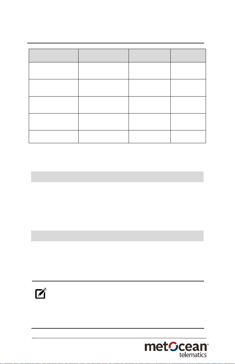
The iBCN-OEM head assembly is a modular component
that may be used in different power configurations as
outlined below:
Configuration
Power Source
Dimensions
Mass
iBCN
9x CR123A cells
Ø 2.2” x 15.5”
810g
iBCN Infinity
9x CR123A cells
Ø 2.63” x 15.4”
960g
iBCN-7
7x D Alkaline cells
(Lithium available)
Ø 2.2” x 20.75”
3550g (Alk)
3200g (Li)
iBCN-3
3x D Lithium cells
Ø 2.2” x 11.25”
1500g
iBCN – User Manual
TD 13 – 053
12
Table 1: MMI Power Configurations
4.2 Antenna
The iBCN is supplied with a dual band combined GPS
and Iridium patch antenna. It is integrated inside the
head assembly, pre-tuned at the factory, and is not user
serviceable.
4.3 Pressure Case
When mounting the pressure case, take care to prevent
any side loading on the head assembly. Over time, side
loading on this part could cause a leak.
NOTE:
To minimize corrosion, NEVER mount the
pressure case directly to metal. Isolate the pressure
case by wrapping it with vinyl tape or a similar material
at the contact points.
Configuration
Power Source
Dimensions
Mass
iBCN-RH
6x C Alkaline cells
(Lithium available)
Ø 3.5” x 4.0” +
Ø 1.75” x 21.5”
2700g
iBCN-RH2
9x CR123A cells
Ø 2.2” x 15.5”
810g
iBCN-RH2-M7
7x D Lithium cells
(Lithium available)
Ø 2.2” x 20.75”
3550g (Alk)
3200g (Li)
iBCN-RH2-M3
3x D Lithium cells
Ø 2.2” x 11.25”
1500g
iBCN-OEM
Custom Power
Ø 2.2” x 2.21”
220g
iBCN – User Manual
TD 13 – 053
13
5 Operating Instructions
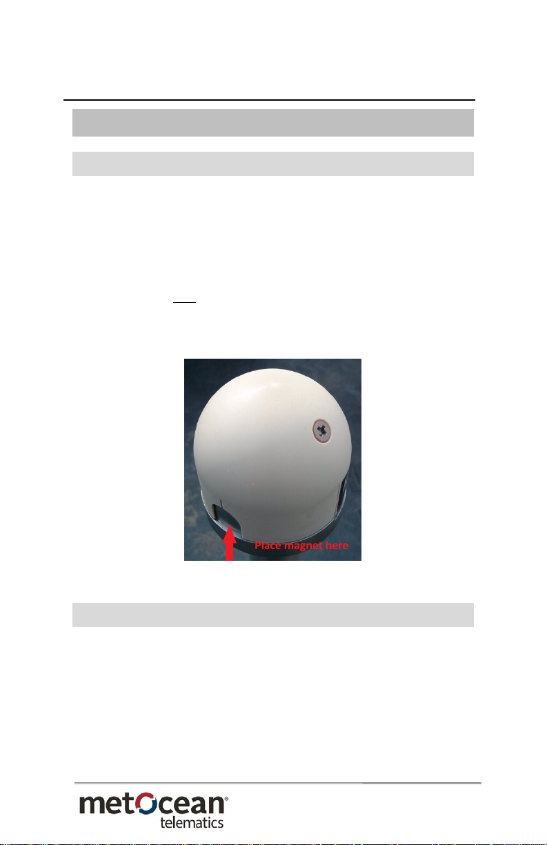
5.1 On/Off
The device may be forced to the low-power Sleep mode
by actuating the magnetic reed switch, located on the
head assembly (identified by a circle or flat surface) with
an externally placed magnet.
The device is ON by default when power is applied and
the magnet is used to force the assembled beacon to
Sleep for extended power savings.
Figure 1: Magnet Placement on Head Assembly
5.2 Batteries
The iBCN has several battery power options available.
Install batteries with the positive terminal towards the
head assembly.
The circuit is reverse polarity protected. Rechargeable
batteries are not recommended.
iBCN – User Manual
TD 13 – 053
14
Always remove batteries when the iBCN is not in use.
Please refer Section 7.2 for battery change details.
NOTE:
Following disconnecting the head assembly
from the batteries, wait for a period of two minutes
before reconnecting. This period of time is required to
let the circuit fully discharge and ensures that the
device will function optimally.
5.3 Test Operation
The following quick test verifies that the iBCN in
standard configuration is functioning properly:
1. Turn device ON by attaching power source (battery
tube) and ensuring the magnet is removed. For the –RH
version (Remote Head), confirm power is applied to the
head assembly.
2. Confirm the iBCN is transmitting Iridium messages by
using an Iridium message detector like the MetOcean
telematics iON Iridium Detector.
3. Alternatively, verify the transmitted data has been
received and processed by the configured data delivery
option. This step validates the Iridium modem
provisioning setup and messages are being delivered
properly.
4. iBCN IS READY TO BE DEPLOYED!

iBCN – User Manual
TD 13 – 053
15
6 Operation
The iBCN is primarily intended for locating and
recovering free drifting or moored, surface or
submerged assets at sea.
After being turned on, the iBCN can be submerged where
it is deactivated by detecting submergence. The iBCN can
be deployed underwater for up to 24 months.
The iBCN may be configured to use a GPS Satellite Check
to determine when the beacon has surfaced. While
submerged, the iBCN will not detect any GPS signal and
this is used to power down the electronics to conserve
battery power.
The sampling of GPS signal is a user-configurable option
to adjust surface response time while maintaining
suitable mission life.
The iBCN (7500 meter version only) is also equipped
with a conductivity sensor to monitor submergence
state. This is a lower power method of detecting the
surface compared to the GPS Satellite Check method.
The sensor samples for a period of one second at the
same interval as the GPS interval to a maximum of 5
minutes.
NOTE:
It may take up to 5 minutes after surfacing
for the first sensor sampling to occur. Depending on
sea conditions it may take a few intervals before the
iBCN realizes it has surfaced and begins to transmit
its location.

iBCN – User Manual
TD 13 – 053
16
The recommended short interval of 2-5 minutes can be
used for all deployments using conductivity water sense
to get notified about the location of your asset.
The iBCN can be reconfigured via Over-The-Air (OTA)
commands to lengthen the GPS/Reporting interval to
conserve battery power and limit data usage if necessary
or to shorten the interval for retrieval.
Due to specifics of the Iridium communication scheme,
the iBCN is able to receive incoming commands only
when it sends reports out or is scheduled to perform a
Mailbox check.
The surfaced iBCN will continue to send its GPS position
messages until it is manually turned off, the battery pack
is depleted, or it returns back to the submerged position.
iBCN – User Manual
TD 13 – 053
17
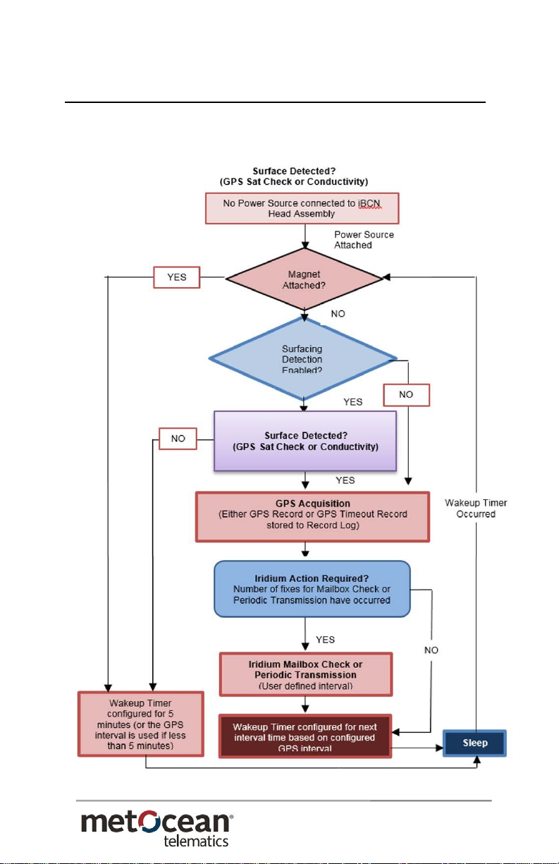
The following flow chart outlines the activation sequence
and timing of the iBCN operation.
Figure 2: iBCN Activation Sequence

iBCN – User Manual
TD 13 – 053
18
6.1 Operating Notes
The Bluetooth connection is available for at least 10
minutes upon initial power-up of the device with the
magnet removed.
Each Bluetooth command sent to the device resets the
Bluetooth timeout period extending the connection time.
The Bluetooth connection is shut down after the
connection time expires to conserve power.
To re-activate the Bluetooth connection, the power
source must be removed and re-attached. It is important
to leave the power source disconnected for at least 2
minutes before reconnecting to ensure a fresh power-up
sequence otherwise the Bluetooth connection may not
be enabled.
The default configuration GPS interval is 5 minutes with
a transmission occurring at every interval. This is a rapid
reporting behavior that is useful during testing and
initial deployment.
Re-configuration using the local Bluetooth connection or
MetOcean LiNC Web-based platform Over-The-Air
interface is recommended to extend mission life.
The iBCN starts in a “Test Mode” upon initial power-up
that will transmit GPS location every 5 minutes for 1
hour regardless of the pre-configured intervals.
After “Test Mode” expires, the iBCN will continue to
operate based on the pre-configured intervals.
This manual suits for next models
2
Table of contents


