iStartek VT900-L User manual

File Name
VT900-L User Manual
Ver.
1.3
Update
2018-09-10
Page
1 of 13
Copyright Statement © 2019 Shenzhen iStartek Technology Co., Ltd. All rights reserved.
iStartek Vehicle GPS Tracker
VT900-L 4G Tracker
User Manual V1.0

File Name
VT900-L User Manual
Ver.
1.3
Update
2018-09-10
Page
2 of 13
Copyright Statement © 2019 Shenzhen iStartek Technology Co., Ltd. All rights reserved.
Content
1、版权与免责声明.................................................................................................... 错误!未定义书签。
2、产品概述............................................................................................................ 错误!未定义书签。
3、产品功能............................................................................................................ 错误!未定义书签。
4、产品规格............................................................................................................ 错误!未定义书签。
5、产品和配件 ................................................................................................................................. 5
5.1、标准配件 .......................................................................................................................... 5
5.2、可选配件 .......................................................................................................................... 5
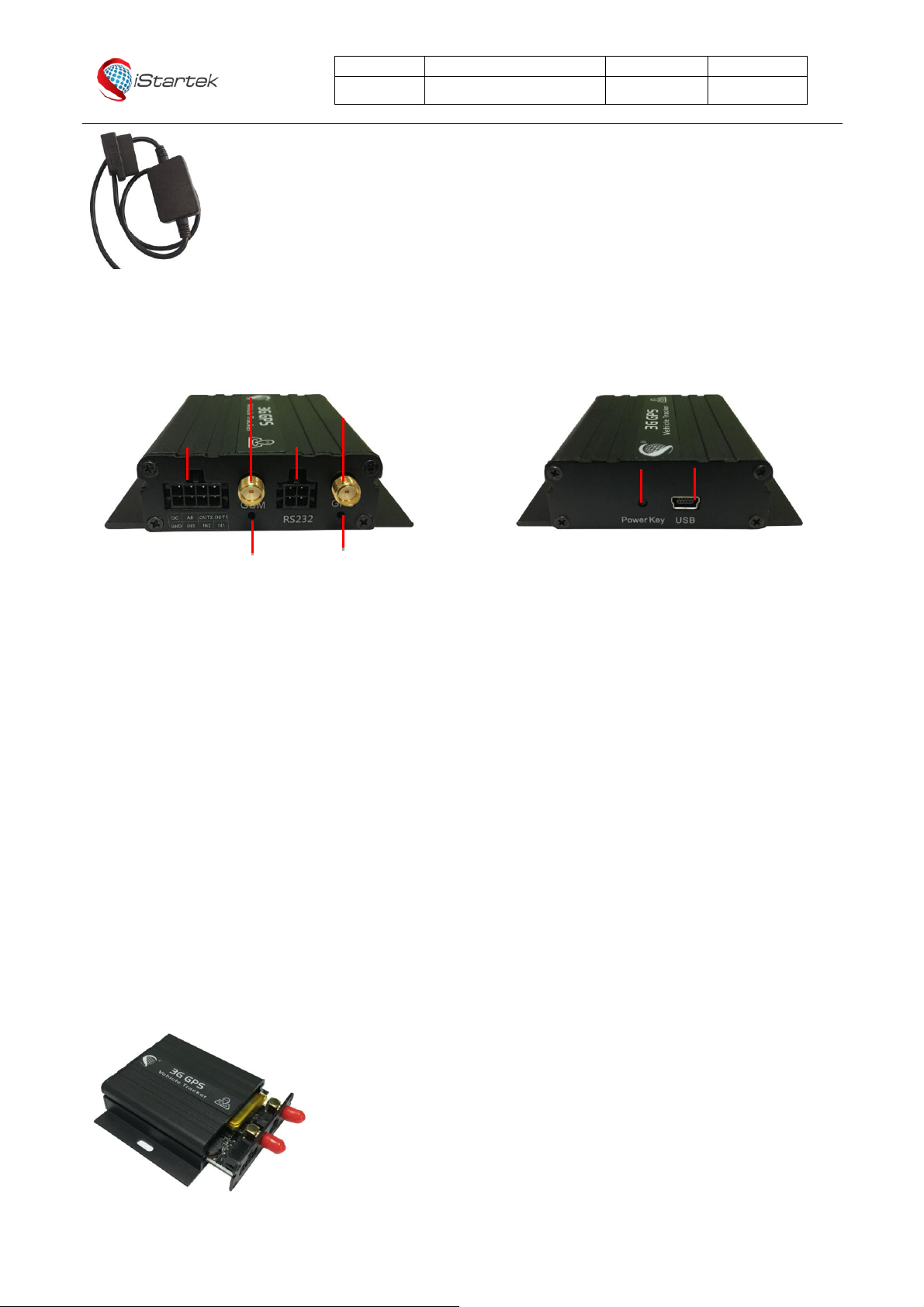
6、产品外观.................................................................................................................................... 6
7、产品使用.................................................................................................................................... 6
7.1、充电................................................................................................................................ 6
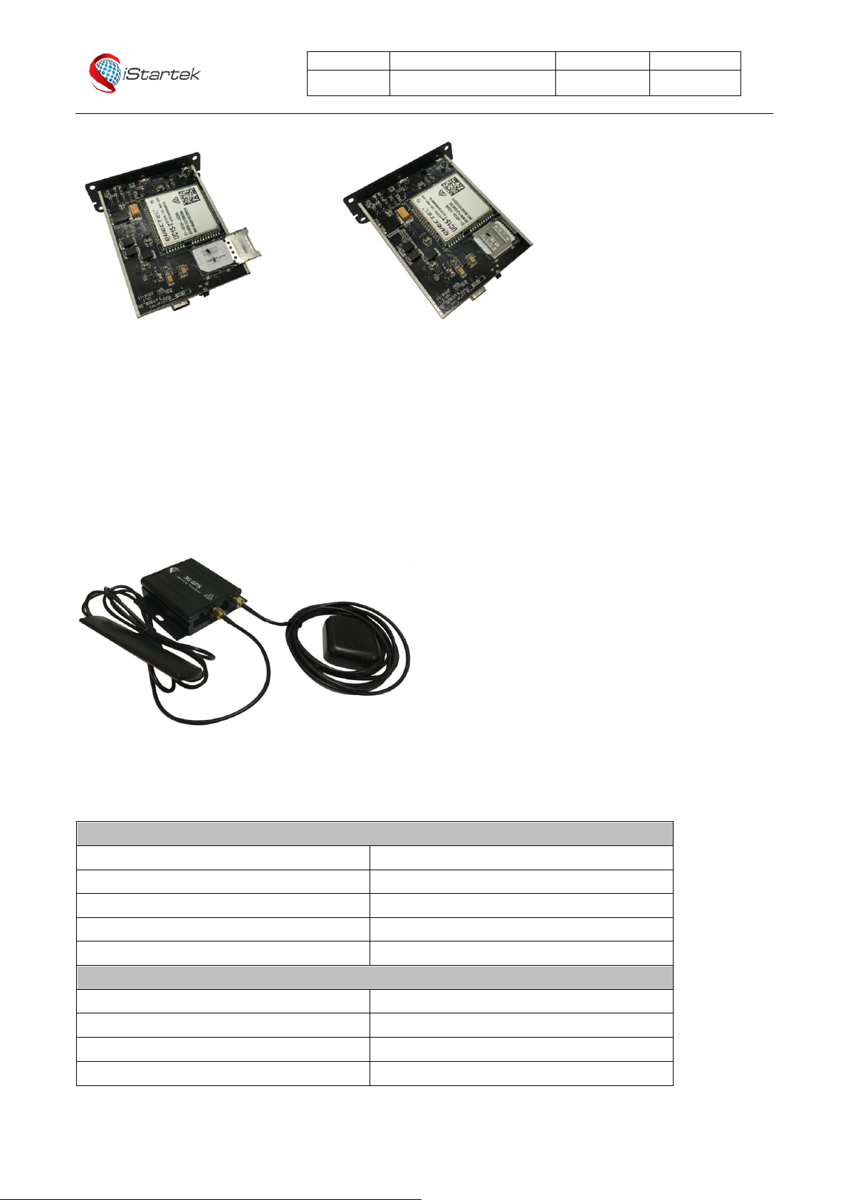
7.2、安装SIM卡........................................................................................................................ 6
7.3、安装GSM/GPS天线 ............................................................................................................. 7
7.4、设备开机 .......................................................................................................................... 7
7.5、电话定位追踪..................................................................................................................... 8
7.6、短信定位追踪..................................................................................................................... 8
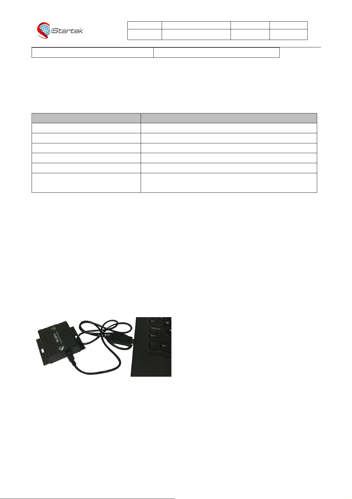
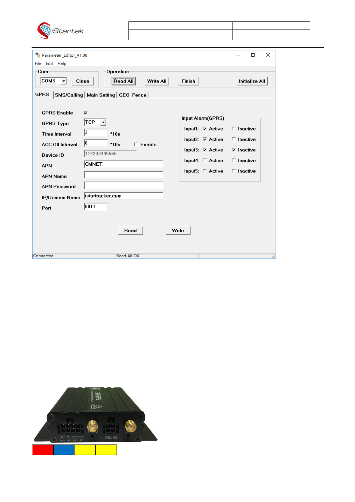
7.7、参数配置 .......................................................................................................................... 8
7.8、平台定位追踪..................................................................................................................... 9
8、产品安装.................................................................................................................................... 9
8.1、输入/输出线功能介绍........................................................................................................... 9
8.2、RS232接口 ..................................................................................................................... 10
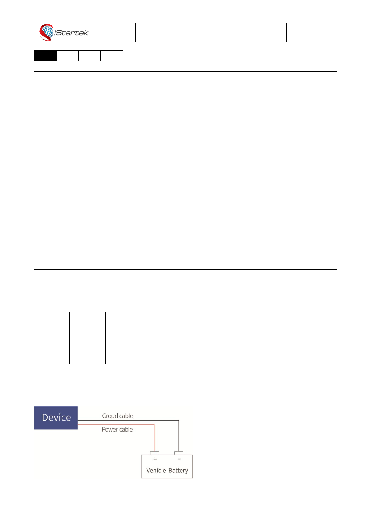
8.3、电源线/地线安装............................................................................................................... 10
8.4、数字输入线安装................................................................................................................ 11
8.5、模拟量输入安装................................................................................................................ 11
8.6、输出控制线安装................................................................................................................ 12
8.7、温度传感器安装(定制) .................................................................................................... 12
8.8、RFID读卡器安装............................................................................................................... 12
8.9、iButton安装(定制)......................................................................................................... 13
8.10、磁读卡器安装(定制)...................................................................................................... 13
8.11、超声波油量传感器安装...................................................................................................... 14
8.12、酒精传感器安装(定制)................................................................................................... 14
8.13、OBD盒子安装(定制)..................................................................................................... 14

File Name
VT900-L User Manual
Ver.
1.3
Update
2018-09-10
Page
3 of 13
Copyright Statement © 2019 Shenzhen iStartek Technology Co., Ltd. All rights reserved.
1. Copyright and Disclaimer
Copyright © 2019 Shenzhen iStartek Technology Co., Ltd.
iStartek and is a registered trademark of Shenzhen iStartek Technology Co., Ltd.
This user manual shallnot be reproducedfor any purpose or transmitted in any way without written authorization of iStartek
company.
iStartek shall not be liable for any direct or indirect damages (included but not limited to economic losses, personal damage,
loss of property and assets) caused by the use, non-use or improper use of this product or documentation.
2. Product Overview
VT900-L is a 4G LTE network based GPS Car tracker with inbuilt high-precision GPS positioning module. Device
report location and vehicle status to vehicle tracking platform through the LTE network, and performs real-time
monitoring, anti-theft and dispatch management of the vehicle. It can be applied to fleet management, public
transportation management, school bus management, taxi operation management, vehicle insurance
management, car leasing management and private car anti-theft.
VT900-L has built-in 8MB Flash memory. When the device cannot connect to the service platform to send data (no
GSM network, service platform downtime, etc.), the historical positioning data will be automatically saved. When
the device returns to normal, the historical positioning data will be automatically resending to server.
The VT900-L contains an RS232 port that can be connected to peripherals such as RFID and magnetic card readers
to perform identification and vehicle control for vehicle drivers. You can also read the car ECU data from the OBD
box.
3. Product Features
GPS+GSM Dual mode localization
Dual server data transmission(Optional)
Real time tracking
Track by time interval
Track by distance
Heading change report
Track by SMS command
SOS alarm
External power cut alarm
Engine, door status change alarm
Geo-fence
Overspeed alarm
GPS blind area alarm
Accelerated alarm
Deceleration alarm
Internal battery low power alarm

File Name
VT900-L User Manual
Ver.
1.3
Update
2018-09-10
Page
4 of 13
Copyright Statement © 2019 Shenzhen iStartek Technology Co., Ltd. All rights reserved.
External power supply low power alarm
Mileage report
8 MB Flash memory
GPS Log
FOTA
Authorization limit firmware upgrade and parameter configuration
Set different time interval when ACC ON、ACC OFF
Remotely control fuel/electricity
GSM anti-jamming(optional)
Tow alarm(optional)
RFID、iButton Driver identification(optional)
Buzzer alarm(optional)
Capacitive fuel sensor(optional)
Ultrasonic fuel sensor(optional)
Temperature sensor(optional)
Alcohol sensor(optional)
OBD Box(Optional)
4. Product Specification
Item
Specification
Size
65 x 61 x 26mm
Weight
106g
Input voltage
DC 9 - 36V/1.5A
Inbuilt battery
500mAh/3.7V
Standby
65mA/h
Working time
33hours in power saving mode and 7.5 hours in normal mode
Working temperature
-20℃~ 55℃(Normal temperature battery)
-10℃~ 80℃(High temperature battery)
Working humidity
5% to 95%
LTE/WCDMA/GSM Band
LMN:Cat-M/NB/GSM
LTE-FDD: B1/B2/B3/B4/B5/B8/B12/B13/B17/B18/B19/B20/B25*/B26*/B28
LTE-TDD: B39 (for Cat M only)
EGPRS: 850/900/1800/1900MHz
LEC(EU):Cat-1
LTE-FDD: B1/B3/B7/B8/B20/B28
WCDMA: B1/B8
GSM: B3/B8
LNS(US):Cat-1
LTE-FDD: B2/B4/B5/B12/B13/B25/B26

File Name
VT900-L User Manual
Ver.
1.3
Update
2018-09-10
Page
5 of 13
Copyright Statement © 2019 Shenzhen iStartek Technology Co., Ltd. All rights reserved.
WCDMA: B2/B4/B5
GPS Sensitivity
-165dB
Positioning Accuracy
2.5 meter
LED Indicator
2 LED indicators GPS/GSM status indicating
Antennas
External GSM antenna,external GPS antenna
Flash memory
8MB(16192 GPRS,256 SMS buffer)
Sensor
Vibration sensor
I/O
3 digital inputs (1 negative trigger,2 positive trigger)
1 analog input(0~24V)
2 outputs
1 RS232
1 USB for configuration
IN2 could be customized as AD2
IN2 could be customized as 1-wire
5. Product and Accessories
5.1、Standard accessories
Main Unit Power cable GPS Antenna GSM Antenna
5.2、Optional Accessories
RFID Reader RFID Tag iButton Reader iButton Tag
Ultrasonic Fuel Sensor Capacitive Fuel Sensor Temperature Sensor Relay
Magnetic Card Reader USB Cable Buzzer Alcohol Sensor

File Name
VT900-L User Manual
Ver.
1.3
Update
2018-09-10
Page
6 of 13
Copyright Statement © 2019 Shenzhen iStartek Technology Co., Ltd. All rights reserved.
OBD BOX
6. Product Appearance
7. Production Operation
7.1、Charging
For the first time using the VT900-L, please connect the DC (positive) andGND (ground) to the 12V or 24V power supply
for at least 2 hours to ensure sufficient power. After configurationand testing, install it on the vehicle.
7.2、Insert SIM Card
VT900-L support 2G. 3G. 4G network.
Please ensure that the SIM card has sufficient balance, and has opened the GPRS/3G/4G function andobtained the
correct APN of the SIM card;
Please make sure that the PIN lock functionof the SIM card has been turnedoff;
If you need to use the call to reply to the location information function, please make sure that the SIM card has caller ID
function;
Make sure the device is turned off before installing the SIM.
a. Unscrewthe front baffle screwand take out the PCBA
Power Port
RS232
GSM Connector
GPS Connector
GSM Indicator
GPS Indicator
ON/OFF
USB

File Name
VT900-L User Manual
Ver.
1.3
Update
2018-09-10
Page
7 of 13
Copyright Statement © 2019 Shenzhen iStartek Technology Co., Ltd. All rights reserved.
b. Insert SIM Card:
c. Fit on PCBA and screw on
7.3、GSM/GPS antenna connection
Connect GSMantenna on the SMA connector labeled"GSM" and connect the GPSantenna on the SMA connector labeled
"GPS" , also ensure that both antennas are tightened.
The GSM antenna can be hidden in any place away fromthe power supply and cannot be attached to the metal surface,
otherwise it will affect the GSM signalstrength.
GPS antenna is used to receive satellite signalin the sky and shouldbe fixed to face the sky and can not be installed in a
place with metal shielding.
7.4、Turn on VT900-L
Longpress the ON/OFF button for 3-5 sec, or connect to the external power supply, VT900-L will start up.
LED operation status:
GPS Indicator(blue)
On
Input is active
Off
Device Turn off or in sleeping mode
Flashing(every 0.1 sec)
GPS module is starting up or restarting
Flashing(0.1 sec on and 2.9 sec off)
VT900-L Received GPS signal
Flashing(1 sec on every 2 sec)
No GPSsignal
GSM Indicator(green)
On
A call is coming in/a call is being made
Off
Device Turn off or in sleeping mode
Flashing(every 0.1 sec)
GPS module is starting up or restarting
Flashing(0.1 sec on and 2.9 sec off)
VT900-GReceived GSM signal

File Name
VT900-L User Manual
Ver.
1.3
Update
2018-09-10
Page
8 of 13
Copyright Statement © 2019 Shenzhen iStartek Technology Co., Ltd. All rights reserved.
Flashing(1 sec on every 2 sec)
No GSM signal
7.5、Track by phone
Make a missed call to the tracker and it willreport its location by SMS with the following Google link format, clicking on the
link the location willbe shown directly on your mobile phone.
SMS content description:
142161102222,Current! 20171123 15:53,A,0Km/h,http://maps.google.com/?q=22.540103,114.082329
Content
Instruction
142161102222
ID number
Current!
Alarmcharacter, different alarm events have different alarmcharacter
20171123 15:53
Date and time,YYYYMMDD hh:mm
A
GPS status, A is valid, V is invalid
0Km/h
GPS speed
http://maps.google.com/?q=22.540103,114
.082329
Google link
7.6、Track by SMS
Send SMS command to VT900-L, W000000,100
The device will receive a text message with a link to Google maps. Clicking on the link will display the current
location of the device on Google maps.
Please refer to 《iStartek SMS Protocol》for SMS descriptions and more SMS commands.
7.7、Parameter Configuration
Download and install USB cable driver《PL2303_Prolific_Driver》。
Connect VT900-L to the computer via USB cable. OperatingParameter Editor configuration software and open the port.
Press the on/ off button for 1sec to make device enter Parameter Editor configurationstate.

File Name
VT900-L User Manual
Ver.
1.3
Update
2018-09-10
Page
9 of 13
Copyright Statement © 2019 Shenzhen iStartek Technology Co., Ltd. All rights reserved.
For more parameters configuration, please refer to the user guide of Parameter Editor.
7.8、Platformlocation tracking
You can set server IP, Port and APN, GPRS interval by SMS commands 011, 012, 013, 014, or you canuse Parameter
Editor software to configure related parameters.
For more SMS command functions and parameter configuration, please refer to《iStartek SMS Protocol》and
《Parameter Editor User Guide》。
8. Product Installation
1.1. 8.1、Functions introduction for Inputs/outputs
DC
AD
OUT2
OUT1

File Name
VT900-L User Manual
Ver.
1.3
Update
2018-09-10
Page
10 of 13
Copyright Statement © 2019 Shenzhen iStartek Technology Co., Ltd. All rights reserved.
GND
IN3
IN2
IN1
PIN
Color
Function
DC
Red
DC In (power input). Input voltage: 9V~36V. 12V/24V suggested.
GND
Black
Ground
IN1
White
Digital input 1, negative trigger.
Can be used to connect SOS button.
IN2
White
Digital input 2, positive trigger.
Can be used to connect the startingdoor trigger signal line and detect the status of the door.
IN3
White
Digital input 3, positive trigger.
Can be used to connect ACC and detect the ignition status of the car.
OUT1
Yellow
Output 1. Lowlevel (0V) when the output is valid, open leakage output (OD) when it is invalid.
The maximum withstandvoltage of open leakage output (invalid) is 45 v.
The maximum withstandcurrent at low voltage is 500 ma.
Externalrelays can be connected to remotely cut off the oil line/engine power supply, etc.
OUT2
Yellow
Output 2. Lowlevel (0V) when the output is valid, open leakage output (OD) when it is invalid.
The maximum withstandvoltage of open leakage output (invalid) is 45 v.
The maximum withstandcurrent at low voltage is 500 ma.
It can be connected with external buzzer alarm, etc.
AD
Blue
10-digit analog input, effective input voltage value is 0-24v.
Can be used to connect external sensor, such as fuel sensor, etc.
8.2、RS232 Port
RS232 portcan connect with RFID, magnetic card reader and other accessories.
1
DC 5V
output
3
VT900 RX
2
GND
4
VT900 TX
8.3、GND installation
Connect respectively the power cable andGND to the positive pole andnegative pole of the car battery to give Power
supply:

File Name
VT900-L User Manual
Ver.
1.3
Update
2018-09-10
Page
11 of 13
Copyright Statement © 2019 Shenzhen iStartek Technology Co., Ltd. All rights reserved.
8.4、Digital inputs installation
Input3 can be connected to the ignition switch of the car to detect the ignition.
Input1 or Input2 can be connected to the car door to detect the status of the door.
Input1 (VIL) can also be connected to PIN switch to detect the status of hood:
8.5、Analog Input (AD1) installation
Analog input range is 0-24v, it can be connectedto the voltage output type sensor, such as fuel sensor.
Input voltage calculation formula:Input Voltage=(AD*24)/1024
Example:
094506.000,A,2232.5412,N,11404.6919,E,0.00,,290709,,*12|1.7|110|0000|00AA,0000
AD = 0x00AA = 170
Input Voltage=(AD*24)/1024=(170*24)/1024=3.984375V.
Example: Analog input connect with fuel sensor,Yellow-green wire of the sensor is connected to the blue wire of VT900 L.
Output voltage of the sensor is 0V when the fuel tank is empty, Output voltage of the sensor is 5V when the fuel Tank is full.
Calculate the percentage of Remaining oil:
Oil percentage = (((AD*24)/1024)/5)*100%

File Name
VT900-L User Manual
Ver.
1.3
Update
2018-09-10
Page
12 of 13
Copyright Statement © 2019 Shenzhen iStartek Technology Co., Ltd. All rights reserved.
8.6、Output Control wire installation
Output can be connected with relay to cut off oil/electricity and control the vehicle. Can also be connected to a buzzer.
8.7、Temperature sensor installation (customized version)
Customized hardware and software versions are required when the device connect the temperature sensor.
Need to customize input2 to1-wire cable, change the AD line to the 5V voltage supply of the temperature sensor,the wiring
diagramas follows:
8.8、RFID Card Reader installation
Device connect with RFID Reader can prevent driver start vehicle illegally,the wiring diagramas follows:
When the driver starts the vehicle without swipingthe authorized card, it is considered to start illegally, and the device will

File Name
VT900-L User Manual
Ver.
1.3
Update
2018-09-10
Page
13 of 13
Copyright Statement © 2019 Shenzhen iStartek Technology Co., Ltd. All rights reserved.
automatically disconnect the oil and electricity and fail to start the vehicle.
Related SMS commands please refer to iStartek SMS protocoland iStartek GPRS Protocol.
8.9、iButton Installation (customized version)
Customized hardware and software versions are required, need to customize input2 to1-wire cable.
Device connect with ibutton can prevent driver start vehicle illegally,the wiring diagramas follows:
When the driver starts the vehicle without swiping the authorized card, it is considered to start illegally, and the device will
automatically disconnect the oil and electricity and fail to start the vehicle.
For related parameter setting instructions, please refer to iStartek SMS protocol and iStartek GPRS Protocol.
8.10、Magnetic Card Reader installation (customized)
Customize the software version for DLT.
For related parameter setting instructions, please refer to iStartek SMS protocol and iStartek GPRS Protocol.

File Name
VT900-L User Manual
Ver.
1.3
Update
2018-09-10
Page
14 of 13
Copyright Statement © 2019 Shenzhen iStartek Technology Co., Ltd. All rights reserved.
8.11、Ultrasonic fuel sensor installation
The height measurement range of ultrasonic fuelsensor is fixed at 0~100cm (100-200cm customizable), and the
corresponding output voltage range is 0~5V.
Formula to calculate oil height:h=(((AD*24)/1024)/5)*100cm
8.12、Alcohol sensor installation (Customized version)
Customized firmware version is required when the device is connected to an alcohol sensor.
The AD line of the device is connected to the voltage output line of the alcohol sensor, and the red line of the
alcohol sensor is connected to the 5V voltage. The wiring diagram is as follows:
8.13、OBD BOX installation (Customized version)
Customized firmware version is required for connecting with OBD Box. Customizable reading of the car's
individual data.
For related parameter setting instructions, please refer to iStartek SMS Protocol and iStartek GPRS Protocol.
The wiring diagram is as follows:
If you have anyother questions, please send an email to info@istartek.com, we are happyto serve you.
Table of contents
Other iStartek GPS manuals

iStartek
iStartek VT600 User manual

iStartek
iStartek VT140 User manual

iStartek
iStartek VT900 User manual

iStartek
iStartek VT900-E User manual

iStartek
iStartek VT500 User manual

iStartek
iStartek VT200-L User manual

iStartek
iStartek VT206 User manual

iStartek
iStartek PT21 User manual

iStartek
iStartek VT100-L User manual

iStartek
iStartek VT600 User manual