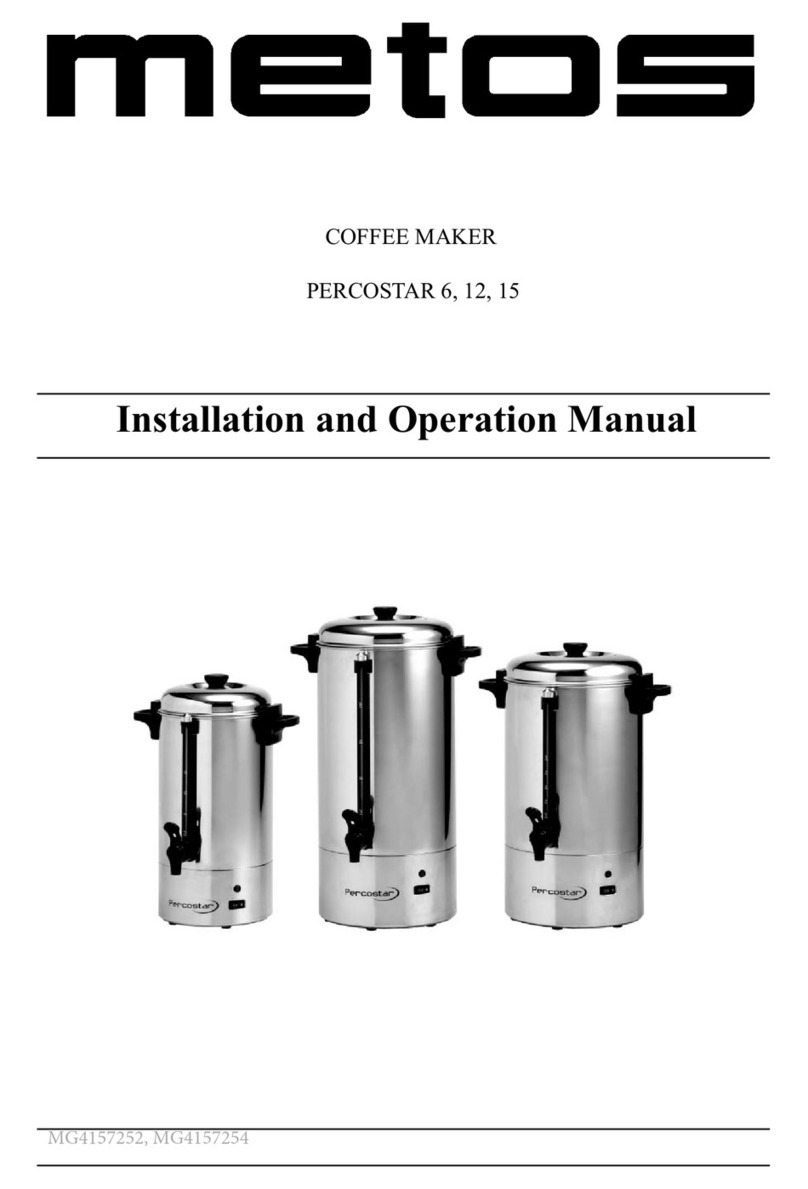
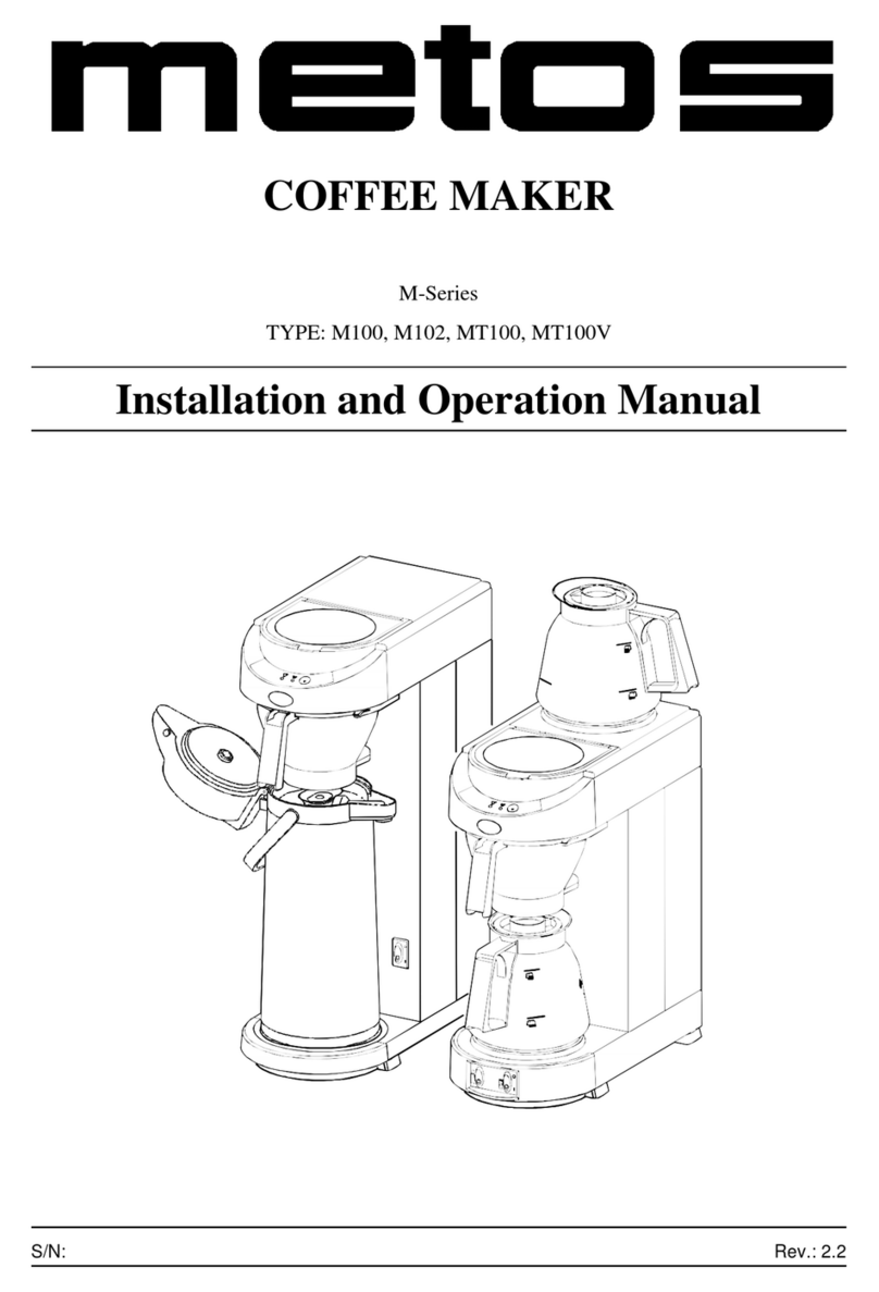
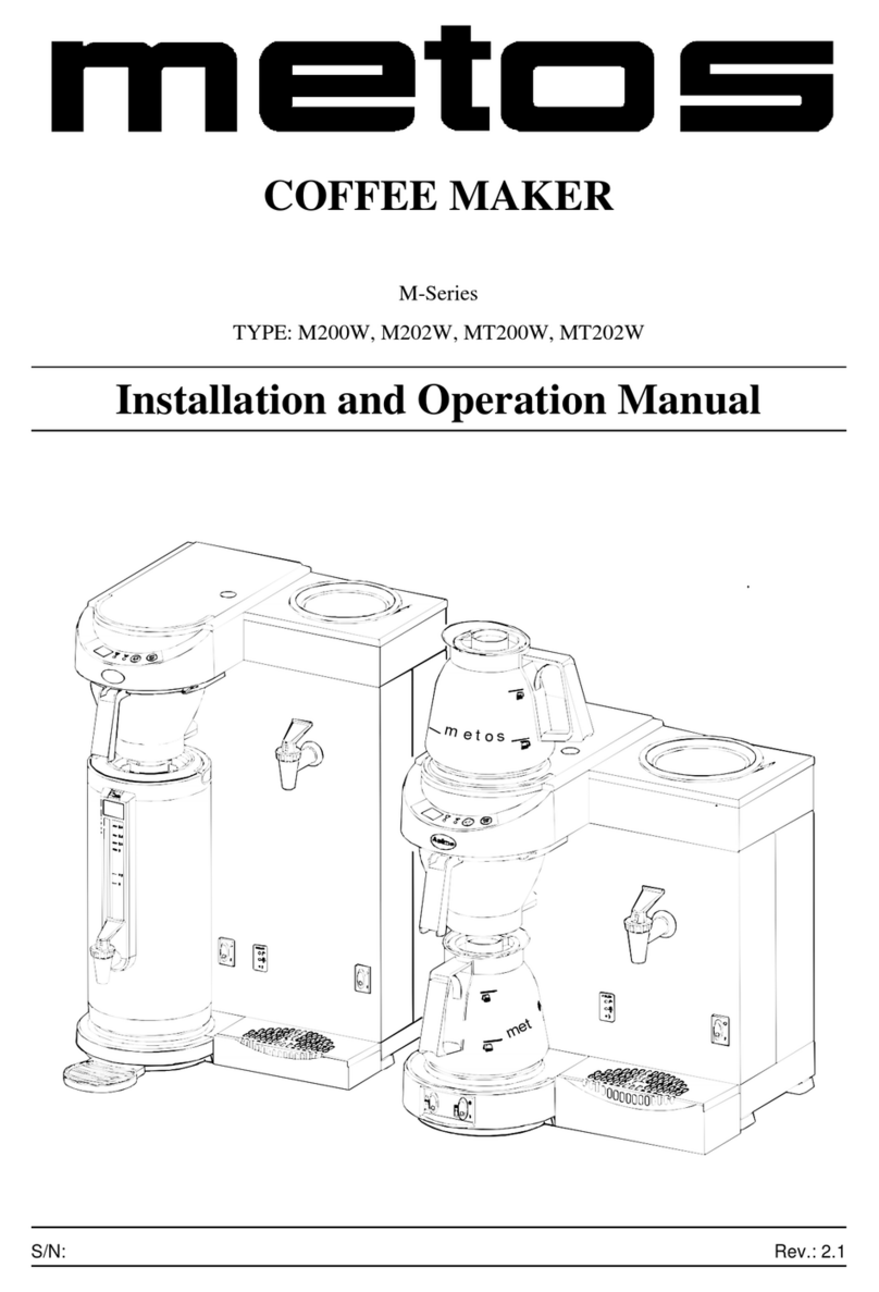
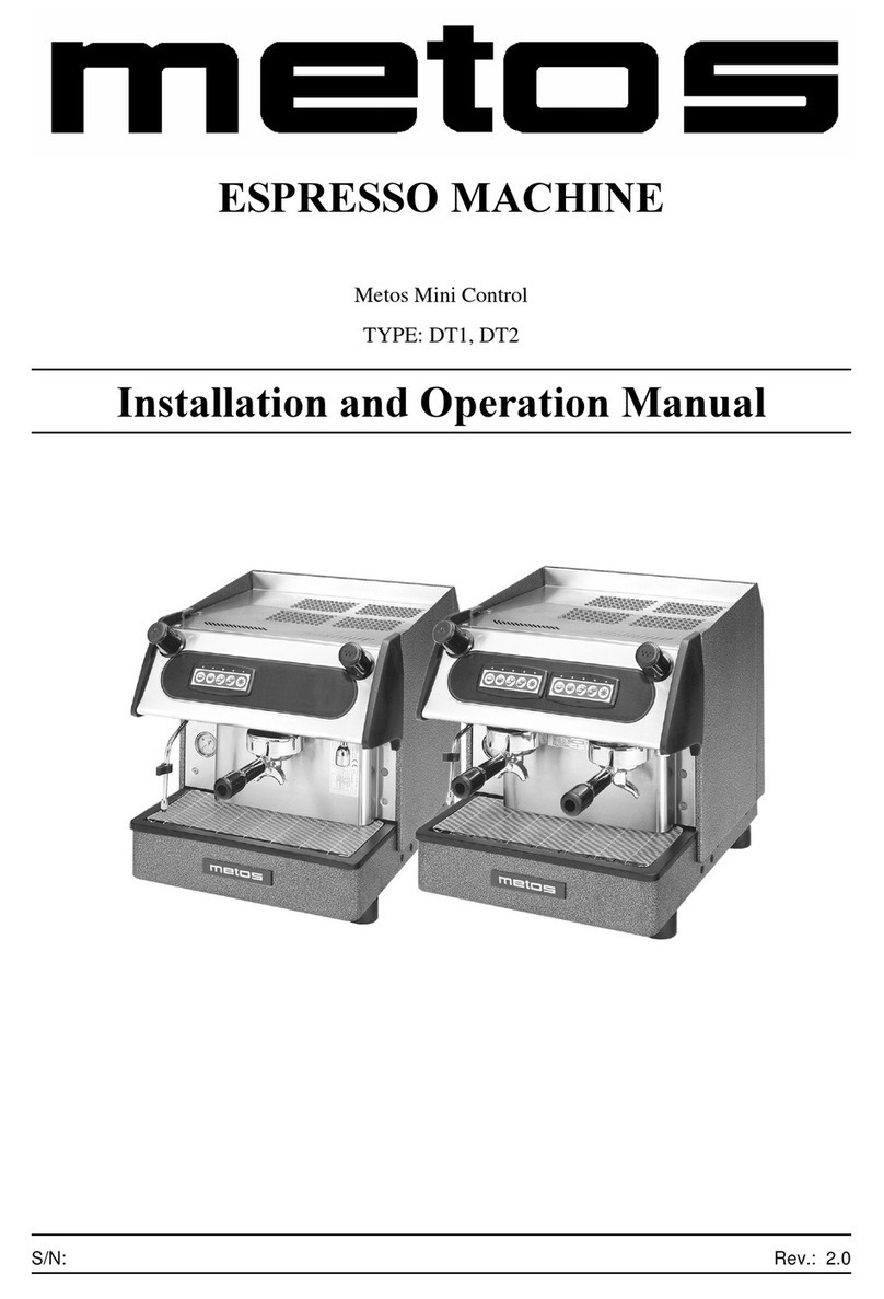
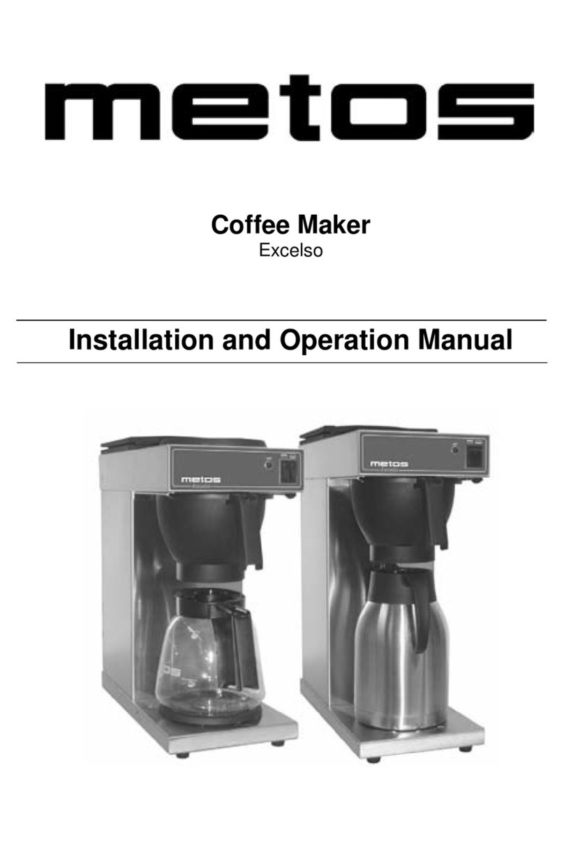
Metos CBW 5W User manual

BULK BREWING COFFEE MACHINE
METOS COMBI
CBW
TYPE: 5W, 1x5WR, 1x5WL, 2x5W, 10W, 1x10WR, 1x10WL, 2x10W, 20W, 1x20WR,
1x20WL, 2x20W
User Manual
S/N: Rev.: 2.2


13.5.2011 Rev. 2.2
Dear Customer,
Congratulations on deciding to choose a Metos appliance for your kitchen activities. You
made an excellent choice. We will do our best to make you a satisfied Metos customer
like thousands of customers we have around the world.
Please read this manual carefully. You will learn correct, safe and efficient working meth-
ods in order to get the best possible benefit from the appliance. The instructions and hints
in this manual will give you a quick and easy start, and you will soon note how nice it is
to use the Metos equipment.
All rights are reserved for technical changes.
You will find the main technical data on the rating plate fixed to the equipment. When you
need service or technical help, please let us know the serial number shown on the rating
plate. This will make it easier to provide you with correct service.
For your convenience, space is providedbelow for you to recordyour local Metos service
contact information.
METOS TEAM
Metos service phone number:...............................................................................................
Contact person:....................................................................................................................

13.5.2011 Rev. 2.2

13.5.2011 Rev.
1. General .......................................................................................................... 1
1.1 Symbols used in the manual .......................................................................................... 1
1.2 Symbols used on the appliance ...................................................................................... 1
1.3 Checking the relationship of the appliance and the manual .......................................... 1
2. Safety .............................................................................................................. 2
2.1 Warnings ........................................................................................................................ 2
2.1.1 Installation ............................................................................................................. 2
2.1.2 Use ......................................................................................................................... 2
2.1.3 Maintenance and troubleshooting .......................................................................... 2
2.2 Safeguards ..................................................................................................................... 3
2.2.1 On/off switch ......................................................................................................... 3
2.2.2 STOP button .......................................................................................................... 3
2.2.3 Swivel arm and container detection ....................................................................... 3
2.2.4 Dry-boil protection ................................................................................................ 3
2.2.5 Warning indication display .................................................................................... 3
2.3 Disposal of the appliance ............................................................................................... 4
3. Functional description .................................................................................. 5
3.1 General .......................................................................................................................... 5
3.2 Models ........................................................................................................................... 5
3.3 Application of the appliance .......................................................................................... 6
3.3.1 Prohibited use/Use for other purposes ................................................................... 6
3.4 Construction [1x5W, 1x10W, 1x20W, 2x5W, 2x10W, 2x20W] ................................. 7
3.5 Contruction [5W, 10W, 20W] ...................................................................................... 9
3.6 Operating switches and indicator lights ..................................................................... 11
3.7 Display ........................................................................................................................ 12
3.8 Error reporting symbols ............................................................................................... 12
4. Operation instructions ............................................................................... 13
4.1 Before using the appliance .......................................................................................... 13
4.1.1 Flushing the flow heater system .......................................................................... 13
4.1.2 Flushing the boiler system ................................................................................... 14
4.1.3 First settings operator menu ................................................................................. 14
4.2 Operation procedures ................................................................................................... 14
4.2.1 Brewing coffee ..................................................................................................... 16
4.2.2 Brewing tea .......................................................................................................... 17
4.2.3 Timer function ..................................................................................................... 18
4.2.4 Drawing off hot water [1x5W, 1x10W, 1x20W, 2x5W, 2x10W, 2x20W] ........ 19
4.2.5 Drawing off hot water [5W, 10W, 20W] ............................................................ 21
13.5.2011 Rev.
4.2.6 Temperature protection ........................................................................................ 22
4.2.7 The operator menu .............................................................................................. 22
4.2.8 Menu functions .................................................................................................... 23
4.2.9 Settings step by step ............................................................................................. 24
4.3 After use ...................................................................................................................... 45
4.3.1 Cleaning .............................................................................................................. 45
4.3.2 Periodic descaling activities ................................................................................. 48
5. Installation ................................................................................................... 49
5.1 General ........................................................................................................................ 49
5.2 Unpacking [1x5, 1x10, 1x20, 2x5, 2x10, 2x20, 1x5W, 1x10W, 1x20W, 2x5W, 2x10W,
2x20W] .............................................................................................................................. 50
5.3 Unpacking [5W, 10W, 20W] ....................................................................................... 51
5.4 Preparation for positioning .......................................................................................... 51
5.5 Water connection ......................................................................................................... 52
5.5.1 Water treatment .................................................................................................... 52
5.6 Water drainage ............................................................................................................. 52
5.7 Electrical connection ................................................................................................... 53
5.8 Connection on a counter .............................................................................................. 54
5.9 Mounting on a wall [5W, 10W, 20W] ......................................................................... 54
6. Troubleshooting .......................................................................................... 56
7. Technical specifications .............................................................................. 57

13.5.2011 Rev. 2.2
General
1
1. General
Carefully read the instructions in this manual as they contain important information re-
garding proper, efficient and safe installation, use and maintenance of the appliance.
Keep this manual in a safe place for eventual use by other operators of the appliance.
The installation of this appliance must be carried out in accordance with the manufactur-
er’s instructions and following local regulations. The connection of the appliance to the
electric and water supply must be carried out by qualified persons only.
Persons using this appliance should be specifically trained in its operation.
Switch off the appliance in the case of failure or malfunction. The periodical function
checks requested in the manual must be carried out accordingto theinstructions. Have the
appliance serviced by a technically qualified person authorized by the manufacturer and
using original spare parts.
Not complying with the above may put the safety of the appliance in danger.
1.1 Symbols used in the manual
This symbol informs about a situation where a safety risk might be at hand. Given instruc-
tions are mandatory in order to prevent injury.
This symbol informs about the right way to perform in order to prevent bad results, appli-
ance damage or hazardous situations.
This symbol informs about recommendations and hints that help to get the best perform-
ance out of the appliance.
This symbol informs about a function that has to be taken into account in self-control.
1.2 Symbols used on the appliance
This symbol on a part informs about electrical terminals behind the part. The removal of
the part must be carried out by qualified persons only.
1.3 Checking the relationship of the appliance and the manual
The rating plate of the appliance indicates the serial number of the appliance. If the man-
uals are missing, it is possible to order new ones from the manufacturer or the local rep-
resentative. When ordering new manuals it is essential to quote the serial number shown
on the rating plate.

13.5.2011 Rev. 2.2
Safety
2
2. Safety
2.1 Warnings
2.1.1 Installation
• Place the appliance at buffet height and on a firm, level base, in such a way that it
can be connected to the water supply and power supply.
• Connect the appliance to an earthed wall socket.
• Position the appliance in such a way that no damage can be caused if it leaks.
• Do not tilt the appliance, always position and move the appliance upright.
• Connect an overflow pipe to the drainage tube.
• Water always remains in the heating system: for this reason the appliance must not
be placed in an area where the temperature can fall below freezing point.
• When installing the appliance, always observe the local rules and use approved
materials and parts.
• The Installation chapter must again be followed when repositioning the appliance.
• Connect the appliance to the cold water mains.
2.1.2 Use
• Inspect the appliance before using it and check it for damage.
• Never submerge or spray the appliance.
• Do not press the buttons with a sharp object.
• Protect the controls against dirt and grease.
• During use some parts will become very hot.
• Do not position the container on open fire, or hot plate.
• First disconnect the electric cable before transporting the container.
• It is advisable to take the plug out of the socket and close the water tap if the ap-
pliance is not going to be used for longer periods of time
2.1.3 Maintenance and troubleshooting
• Observe the descaling intervals indicated by the descaling indicator symbol.
• Overdue maintenance to the heating system can result in high repair costs and an-
nulment of the guarantee.
• Do not leave the appliance unattended when maintenance is being performed.

13.5.2011 Rev. 2.2
Safety
3
• When descaling the appliance, it is advisable to wear safety glasses and protective
gloves.
• Wash your hands after descaling.
• Have all repairs carried out by a qualified technician.
• The plug must be taken out of the socket if the appliance has to be opened for
cleaning or repairs.
2.2 Safeguards
The appliance is fitted with the following safe guards
2.2.1 On/off switch
The on/off switch is used to switch the appliance on and off. Remember that the appliance
can still be live after being switched off! For this reason you should always remove the
plug from the socket to render the appliance voltage-free.
2.2.2 STOP button
The coffee making process can be interrupted at any point using the STOP button located
on the control panel.
2.2.3 Swivel arm and container detection
This appliance is equipped with a safety device through which it is only possible to start
the brewing process if the swivel arm and container are in the correct position. If the swiv-
el arm and/or container are moved out of position during the brewing process, the brewing
process is interrupted, a swivel arm and/or container symbol appears in the display and
there is a sound signal (2x short). Once the positioning fault has been resolved the brewing
process can be restored by pressing the START button.
2.2.4 Dry-boil protection
This appliance is equipped with a dry-boil protection. This protection triggers if the heat-
ing elements overheat owing to a fault. Once the fault has been resolved, the dry-boil pro-
tection can be reset at the outside of the appliance. The most common cause of the dry-
boil protection being triggered is not descaling the heating system in time.
2.2.5 Warning indication display
A technical fault is reported by displaying an error code in the display. The relevant prob-
lem can be localised and resolved with the help of this code. In this case see chapter 13-
Troubleshooting.

13.5.2011 Rev. 2.2
Safety
4
2.3 Disposal of the appliance
No appliance lasts forever. When the time comes to discard your appliance it will usually
be possible to return it to your dealer. If this is not the case, ask your municipal council
about the alternatives for recycling the materials. All plastic parts have been given stand-
ard codes. The parts of the appliance such as the printed circuit board and accompanying
parts form electrical and electronic waste. The metal body is made of stainless steel and
can be completely dismantled.

13.5.2011 Rev. 2.2
Functional description
5
3. Functional description
3.1 General
The ComBi-line 5 - 20 is a professional coffee maker, equipped with a continuous flow
heater. It is very easy to use. The user can choose from a number of fixed set amounts via
a control panel with a graphic display which also offers information about the current
process of the appliance. Specific requirements and wishes concerning brewing quantity,
etc. can be accessed and programmed by the operator via a PIN. The operator also has the
possibility of reading counters and activating a descaling program.
3.2 Models
This manual covers the following coffeemakers of the ComBi-line range:

13.5.2011 Rev. 2.2
Functional description
6
3.3 Application of the appliance
3.3.1 Prohibited use/Use for other purposes
This machine can only be used for brewing and distributing coffee and/or tea. The use of
the appliance for other purposes is not permitted and may be hazardous. The manufacturer
cannot be held liable for losses caused by using the appliance for purposes other than
those indicated here or by incorrect use.

13.5.2011 Rev. 2.2
Functional description
7
3.4 Construction [1x5W, 1x10W, 1x20W, 2x5W, 2x10W, 2x20W]

13.5.2011 Rev. 2.2
Functional description
8
1. Socket L/R for container heating
2. ON/OFF switch coffee system
3. Hot water tap
4. Drip tray with grid
5. Base plate
6. Control panel
6.1 On/Off button boiler system
6.2 STOP button / Back button (without changing)
6.3 Illuminated display
6.4 Selection button brew volume 1
6.5 Selection button brew volume 2
6.6 Selection button brew volume 3
6.7 Selection button brew volume 4
6.8 START button / Accept button (save)
6.9 Timer button
6.10 On/Off button container heating L/R
7. Vapor escape opening boiler system
8. Dry-boil protection
9. Swivel arm
10. Descale filling opening coffee brewing system
11. Descale filling opening boiler system
12. Insulated lid
13. Blender - transport disk
14. Dry-boil protection hot water system
15. Water distributor lid
16. Basket filter
17. Integrated gauge glass
18. Handle
19. Coffee tap
20. Socket with splash protection
21. Pilot light
22. Drain hose coffee brewing system
23. Drain hose hot water system

13.5.2011 Rev. 2.2
Functional description
9
3.5 Contruction [5W, 10W, 20W]

13.5.2011 Rev. 2.2
Functional description
10
1. Socket L/R for container heating
2. ON/OFF switch coffee- and boiler system
3. Hot water tap
4. Drip tray with grid
5. Wall bracket
6. Control panel
6.1 On/Off button boiler system
6.2 STOP button / Back button (without changing)
6.3 Illuminated display
6.4 Selection button brew volume 1
6.5 Selection button brew volume 2
6.6 Selection button brew volume 3
6.7 Selection button brew volume 4
6.8 START button / Accept button (save)
6.9 Timer button
6.10 On/Off button container heating L/R
7. Vapor escape opening boiler system
8. Dry-boil protection coffee brewing system
9. Swivel arm
10. Descale filling opening coffee brewing system
11. Descale filling opening boiler system
12. Dry-boil protection hot water system
13. Drain hose coffee brewing system
14. Drain hose hot water system

13.5.2011 Rev. 2.2
Functional description
11
3.6 Operating switches and indicator lights
A Selection buttons (4x) The selection buttons
are used to select the standard brewing
amount. The chosen amount confirmed us-
ing the display and can be increased or de-
creased using the same selection buttons, as
required.
B STOP buttonUse the STOP button to cancel
a selection or to (emergency) stop a process.
An emergency stop results in the process be-
ing lost,so it must be executed again. This
button can also be used as a cancellation but-
ton if theoperator menu is activated.
C Boiler button Use the hot water button to
switch on the hot water system. After being
switched on, a tapsymbol appears at the top
of the display. The hot water system can be
switched off again using the same button.
D DisplayThe display informs the user about
the status of the most important functions of
the appliance.
E START buttonUse the START button to
start a brewing process. First choose the
brewing amount with one of the selection
buttons. This buttoncan also be used as a
confirmation button if the operator menu is
activated.
F Timer buttonUse the timer button to pro-
gram the brewing process for use at a later
point of time.
G Container heating buttons (2x)Use the con-
tainer heating button to switch the power
sockets that are on the side of the column
ON/OFF. ATTENTION: Only usethe power
sockets for the container heating, do not con-
nect any other electrical appliances. (Maxi-
mum capacity 100W).
H On/Off-switchThis switch is used to turn the
coffee making system ON (I) or OFF (0).
I Power socket

13.5.2011 Rev. 2.2
Functional description
12
3.7 Display
3.8 Error reporting symbols
I Boiler systemThe hot water system is switched
on. The tap symbol can be replaced by the actu-
al boilertemperature display via the operator
menu.
J Brew volume (4x)Each selection button (4x)
displays a pre-programmed brewing amount.
The amountscan be set completely as required
via the settings menu.
K ClockReal time indicator
L Timer; (flashing)The timer function is activat-
ed.
M Scale indicatorOne of the systems must be des-
caled at the first opportunity. Look up 'descal-
ing' in theoperator menu.
N Swivel arm in positionThe swivel arm is in the
correct position above a filter. If the swivel arm
is moved away the symbol disappears from the
display.
O Container in positionThe coffee container with
filter unit is in the correct position. If the con-
tainer is taken away the symbol disappears from
the display.
P Container heatingThe heating of the coffee con-
tainer is switched on. If the heating is switched
offthe symbol disappears from the display.
Q Leaking outThe dripping symbol is displayed if
the hot water dosing is stopped and the filter
unit is leaking.
Container position failureThis symbol appears in the display if the coffee container gets out of
position during a brewing process. The arrow shows on which side the problem occurs.
Swivel armnot in positionThis symbol appears in the display ifthe swivel arm gets out of position
during a making process. The arrow shows on which side the problem occurs.
Swivel armnot in position for new brewing process This symbolappears in the display if a brew-
ing process is started and there is (still) no swivel arm in position above the filter unit.
Press START buttonThis symbol appears after the swivel arm and/or container fault has been re-
solved. For your own safety the start button must always be pressed again. If this report is re-
sponded to within 10 minutes the brewing process will restart and be completed.
If the START button is pressed only after 10 minutes, a cross symbol with a flashing clock ap-
pears in order to indicate that the brewing process can no longer be restored and should be con-
sidered lost.

13.5.2011 Rev. 2.2
Operation instructions
13
4. Operation instructions
4.1 Before using the appliance
When used for the first time the appliance works according to the standard factory set-
tings.
The various settings can be altered by trained, authorized personnel. See “Operator
menu”.
This chapter will explain the coffee brewing and hot water system process.
• when the appliance is used for the first time.
• when the appliance has not been used for more than 1 week, for example after a
holiday period.
4.1.1 Flushing the flow heater system
1. Open the water tap and check if the swivel connections are not leaking.
2. Put the cable with inlet plug into the back of the container and insert the plug into
the socket of the flow water heater (fig. 1-1).
3. Check if the containers are positioned correctly, with a filter unit (still without cof-
fee), and position the swivel arm above the centre of the filter.
4. Switch the appliance on by putting the ON/OFF switch (fig. 1-2) in position I, the
display (fig. 1-5.2)lights up and you will hear a beeping sound. Then the display
will indicate the standard choices.
5. Press selection button 2 (fig. 1-5.4) and confirm your choice by pressing the
START button (fig. 1-5.7). The coffee system starts filling and the brewing proc-
ess starts. In the display appears the text: BREWING. With the STOP button
(fig.1-5.1) the brewing process can be interrupted at any moment. When the wa-
tersupply stops coming out of the swivel arm, you will hear a beeping sound (1x
short). In the display appears the text: LEAKING. The leaking time is set as stand-
ard to approx. 5 minutes, and its ending is indicated by a beeping sound (3x short).
6. Empty the container with the drainage tap (fig. 1-15).
7. Position the swivel arm above the other filter and follow the above procedure once
again if the model is equipped with two containers.
8. Once the container is empty the coffee maker is ready for use.

13.5.2011 Rev. 2.2
Operation instructions
14
4.1.2 Flushing the boiler system
• Switch on temperature indication in display (See “Show temperature” (menu 4.1)
• Change temperature (“Temperature” (menu 4.2))
• Switch on the continuous heating function 97+ (See Switch on the continuous
heating function 97°C+)
The hot water system steam outlet can be found on the top of the tower. Steam can escape
through this opening during normal heating and heating with the continuous heating func-
tion (97°C+) switched on! Do not touch the moisture outlet. There is a danger of burning.
• Press the hot water system on/off button ( ). The hot water system fills itself
automatically, and then heats up. A flashing tap symbol appears in the display.
• The tap symbol stops flashing when the hot water system is hot enough (90°C).
The hot water system can be switched off at any moment by pressing the on/off
button again ( ). The tap symbol disappears from the display and the system
will no longer refill or heat up.
• Draw off approx. 2 litres of water using the no-drip tap (fig. 1-3) and throw it away.
The hot water system fills itself automatically with fresh water.
• The boiler system is now ready for use.
4.1.3 First settings operator menu
The following details are set in the operator menu immediately after being used for the
first time. Please note: The default language setting is English. To gain access to the op-
erator menu system settings see chapter “The operator menu”.
4.2 Operation procedures
This chapter describes the daily use of the appliance by partly qualified personnel. When
the machine is used for the first time, it works in accordance with the standard factory set-
tings. The different settings can be changed later by trained, qualified personnel. See “The
operator menu” for more details.
Inspect the appliance before using it and check it for damage.
Never submerge or spray the appliance.
Do not press the buttons with a sharp object.
Protect the controls against dirt and grease.
System settings (Systeminstellungen) (menu 2)
2.0 Language
2.1 Time
2.2 Date
Coffee settings (menu 3)
3.9 Descale indicator
3.10 Coffee dosing
This manual suits for next models
11
Table of contents
Other Metos Coffee Maker manuals

Metos
Metos MELITTA CUP BREAKFAST User manual

Metos
Metos M100 User manual

Metos
Metos Excelso User manual

Metos
Metos PERCOSTAR 6 User manual

Metos
Metos M200 User manual

Metos
Metos DT1 User manual

Metos
Metos 5 User manual

Metos
Metos Next 4157950 User manual

Metos
Metos M-Series User manual

Metos
Metos MELITTA CUP User manual