Metrodata WCM5100 User manual

WCM5100
Managed Ethernet Extender
V8.38
User Manual
DATE: 10
th
April 2014
DOCUMENT NO:
76
-
02
-
08
7
REVISION: G
PREPARED BY: Ian Banbrook
Metrodata Ltd
Fortune House, Crabtree Office Village
Eversley Way, Egham Surrey, TW20 8RY, UK
Tel +44 1 784 744700
Fax: +44 1 784 744730
E-Mail: support@metrodata.co.uk

METRODATA LTD WCM5100
User Manual
76-02-087 Rev G
2 of
134
METRODATA LTD
No part of this publication may be reproduced, transmitted,
transcribed, stored in a retrieval system, or translated into any
language or computer language, in any form or by any means,
electronic, mechanical, magnetic, optical, chemical, manual or
otherwise, without the prior written permission of
Metrodata Ltd, Fortune House,
Crabtree Office Village, Eversley Way,
Egham, Surrey, TW20 8RY, United Kingdom.
DISCLAIMER
Metrodata Ltd makes no representations or warranties with respect
to the contents hereof and specifically disclaims any implied
warranties or merchantability or fitness for any particular purpose.
Further, Metrodata Ltd reserves the right to revise this publication
and to make changes from time to time in the content hereof without
obligation of Metrodata Ltd to notify any person of such revision or
changes.
Copyright Ó2014 by Metrodata Ltd,
All Rights Reserved

METRODATA LTD WCM5100
User Manual
76-02-087 Rev G
3 of
134
Document Revision History
4th April 2011 XA Document Created
15th April 2011 XB Updated for Multiple VC modes
20th May 2011 A Document Released
29th June 2011 B Document typos corrected
New feature VC-3 allocation added
22nd August 2011 C Updated to add multiple VC-3 with VCAT
and LCAS support
5th September 2013 D Updated manual for 8.23 software
22nd November 2013 E Updated for 8.31 Software
28th February 2014 F Updated for 8.37 software, and addition
on loop back functions.
10th April 2014 G Updated for 8.38 software

METRODATA LTD WCM5100
User Manual
76-02-087 Rev G
4 of
134
TABLE OF CONTENTS
1INTRODUCTION ........................................................................................................10
1.1 WCM5100 Rear Panel ....................................................................................................................................11
1.2 Safety...............................................................................................................................................................11
1.3 Electro Magnetic Compatibility......................................................................................................................12
1.3.1 EN55022 Statement .................................................................................................................................12
1.3.2 FCC Declaration......................................................................................................................................12
1.4 WEEE Directive ..............................................................................................................................................12
1.5 RoHS Compliance ...........................................................................................................................................12
2INSTALLATION .........................................................................................................13
2.1 WCM5100 Rear Panel ...................................................................................................................................13
2.1.1 Mains Power............................................................................................................................................13
2.1.2 DC Power................................................................................................................................................13
2.2 Base Label and Bit Switches ...........................................................................................................................14
2.2.1 WCM5100 Base Label.............................................................................................................................14
2.2.2 Bit Switches.............................................................................................................................................14
2.2.2.1 Bit switch 1, Boot Mode 0...............................................................................................................14
2.2.2.2 Bit switch 2, Boot Mode 1...............................................................................................................15
2.2.2.3 Bit switch 3, DHCP.........................................................................................................................15
2.2.2.4 Bit switch 4, Framing......................................................................................................................15
2.2.2.5 Bit switch 5, Timing Mode..............................................................................................................15
2.2.2.6 Bit switch 6,Unused........................................................................................................................16
2.2.2.7 Bit switch 7, SFP Mode...................................................................................................................16
2.2.2.8 Bit switch 8, Factory Default...........................................................................................................16
2.3 Rackmounting .................................................................................................................................................17
3WCM5100 APPLICATIONS .......................................................................................18
3.1 WCM5100 Normal Mode................................................................................................................................18
3.2 WCM5100 VLAN Trunk Mode ......................................................................................................................18
3.3 VLAN Mode ....................................................................................................................................................19
3.4 S-Tag Mode .....................................................................................................................................................19
4QUICK START CONFIGURATION ............................................................................20
4.1 Cold Start the Unit ..........................................................................................................................................20
4.2 Access the WCM .............................................................................................................................................20
4.3 Logging onto WCM5100 .................................................................................................................................21
4.3.1 User Interface Navigation.........................................................................................................................22

METRODATA LTD WCM5100
User Manual
76-02-087 Rev G
5 of
134
4.4 Configure the WAN interface .........................................................................................................................23
4.4.1 WCM5100 WAN Configuration...............................................................................................................23
4.5 Set IP Address .................................................................................................................................................24
4.6 Set Default Route ............................................................................................................................................25
4.7 Save the Configuration....................................................................................................................................26
5ADVANCED CONFIGURATION ................................................................................27
5.1 System Configuration......................................................................................................................................27
5.1.1 Setting the Time and Date........................................................................................................................28
5.1.2 Setting the Node Name ............................................................................................................................29
5.1.3 Access Control.........................................................................................................................................30
5.1.3.1 Password ........................................................................................................................................30
5.1.3.1.1 Password Recovery ....................................................................................................................31
5.1.3.2 ‘View’User....................................................................................................................................31
5.1.3.3 Super Me........................................................................................................................................31
5.1.3.4 TACACS+......................................................................................................................................32
5.1.3.4.1 Authentication............................................................................................................................32
5.1.3.4.2 Timeout .....................................................................................................................................32
5.1.3.4.3 Retries........................................................................................................................................32
5.1.3.4.4 Server ........................................................................................................................................33
5.1.3.4.5 Encryption Key ..........................................................................................................................33
5.1.4 Welcome Screen......................................................................................................................................34
5.1.5 Software Version .....................................................................................................................................36
5.1.6 Serial Number..........................................................................................................................................36
5.1.7 Output Config..........................................................................................................................................37
5.1.8 Input Config ............................................................................................................................................37
5.1.9 Warm Start ..............................................................................................................................................37
5.1.10 Cold Start............................................................................................................................................38
5.1.11 Event Logs..........................................................................................................................................38
5.1.11.1 System Event Log...........................................................................................................................39
5.1.11.2 Alarm Event Log............................................................................................................................39
5.1.11.3 Config Event Log ...........................................................................................................................40
5.2 Operational Modes..........................................................................................................................................41
5.2.1 VLAN Mode............................................................................................................................................41
5.2.2 Backplane Summary ................................................................................................................................41
5.2.3 Flow Control............................................................................................................................................42
5.2.4 Max Frame Size.......................................................................................................................................42
5.2.5 Rate Limiting Mode.................................................................................................................................43
5.2.6 Priority Management................................................................................................................................44
5.2.6.1 DSCP->C-Tag Mapping..................................................................................................................44
5.2.6.2 Queue Priorities..............................................................................................................................45
5.2.6.3 VLAN Override..............................................................................................................................46
5.2.7 RSTP.......................................................................................................................................................47
5.2.7.1 Mode..............................................................................................................................................47
5.2.7.2 Priority ...........................................................................................................................................47
5.2.7.3 Max Age.........................................................................................................................................47
5.2.7.4 Hello Time .....................................................................................................................................48
5.2.7.5 Forward Delay................................................................................................................................48
5.2.7.6 Tx Hold..........................................................................................................................................48
5.2.7.7 Version...........................................................................................................................................48
5.2.7.8 Status..............................................................................................................................................49
5.2.7.8.1 Port Role....................................................................................................................................49
5.2.7.8.2 Port State ...................................................................................................................................49

METRODATA LTD WCM5100
User Manual
76-02-087 Rev G
6 of
134
5.3 Port Set Up Menu............................................................................................................................................50
5.3.1 LAN Port.................................................................................................................................................51
5.3.1.1 State...............................................................................................................................................51
5.3.1.2 Link Status .....................................................................................................................................51
5.3.1.3 Cable Tester....................................................................................................................................52
5.3.1.4 Auto Negotiation ............................................................................................................................52
(Max)...........................................................................................................................................................52
5.3.1.5 Speed..............................................................................................................................................52
5.3.1.6 (Max) Duplex .................................................................................................................................53
5.3.1.7 Negotiated......................................................................................................................................53
5.3.1.8 MDI/MDIX ....................................................................................................................................54
5.3.1.9 L2 Management..............................................................................................................................54
5.3.1.9.1 Tagging and Priority...................................................................................................................55
5.3.1.9.1.1 C-VLAN Mode....................................................................................................................55
5.3.1.9.1.1.1 VLAN Allocation.........................................................................................................55
5.3.1.9.1.1.2 Untagged......................................................................................................................56
5.3.1.9.1.1.3 Default VLAN .............................................................................................................56
5.3.1.9.1.1.4 Priority Source .............................................................................................................56
5.3.1.9.1.1.5 Default Priority............................................................................................................57
5.3.1.9.1.1.6 Control C-VLAN .........................................................................................................57
5.3.1.9.1.2 QinQ/S-VLAN Mode ..........................................................................................................57
5.3.1.9.1.2.1 Port Mode ....................................................................................................................58
5.3.1.9.1.2.2 S-VLAN (Access Port).................................................................................................58
5.3.1.9.1.2.3 Priority Source (Access Port)........................................................................................58
5.3.1.9.1.2.4 Default Priority (Access Port).......................................................................................59
5.3.1.9.1.2.5 S-VLAN Allocation (Trunk Port ).................................................................................59
5.3.1.9.1.2.6 EtherType (Trunk Port) ................................................................................................59
5.3.1.9.1.2.7 Control S-VLAN..........................................................................................................59
5.3.1.9.2 OAM .........................................................................................................................................60
5.3.1.9.2.1 OAM Mode.........................................................................................................................60
5.3.1.9.2.2 OAM Status.........................................................................................................................61
5.3.1.9.2.3 OAM Counters....................................................................................................................62
5.3.1.9.2.4 OAM Events........................................................................................................................62
5.3.1.9.3 RSTP .........................................................................................................................................63
5.3.1.9.3.1 RSTP Port Priority...............................................................................................................63
5.3.1.9.3.2 RSTP Port Cost ...................................................................................................................63
5.3.1.9.3.3 RSTP Port Fast....................................................................................................................63
5.3.1.10 Link Loss Forwarding.....................................................................................................................64
5.3.1.11 Rate Limiting..................................................................................................................................64
5.3.1.11.1 Limiting....................................................................................................................................65
5.3.1.11.2 CIR...........................................................................................................................................65
5.3.1.11.3 CBS..........................................................................................................................................65
5.3.1.12 Counters.........................................................................................................................................66
5.3.2 SFP Port ..................................................................................................................................................67
5.3.2.1 SFP Type........................................................................................................................................67
5.3.2.2 State...............................................................................................................................................67
5.3.2.3 Link State.......................................................................................................................................67
5.3.2.4 Speed..............................................................................................................................................68
5.3.2.5 SFP Management............................................................................................................................69
5.3.2.5.1 Device Details............................................................................................................................69
5.3.2.5.2 Notifications ..............................................................................................................................70
5.3.2.6 L2 Management..............................................................................................................................70
5.3.2.7 Link Loss Forwarding.....................................................................................................................71
5.3.2.8 Rate Limiting..................................................................................................................................71
5.3.2.9 Counters.........................................................................................................................................71
5.3.3 VCG........................................................................................................................................................72
5.3.3.1 State...............................................................................................................................................72
5.3.3.2 Encapsulation .................................................................................................................................73
5.3.3.2.1.1 GFP FCS.............................................................................................................................73

METRODATA LTD WCM5100
User Manual
76-02-087 Rev G
7 of
134
5.3.3.2.1.2 Strip MAC FCS...................................................................................................................73
5.3.3.2.1.3 Payload Scrambler...............................................................................................................73
5.3.3.3 LCAS/VCAT..................................................................................................................................74
5.3.3.4 LCAS Status...................................................................................................................................74
5.3.3.5 Layer 2 management.......................................................................................................................74
5.3.3.6 Link Loss Forwarding.....................................................................................................................75
5.3.3.7 Rate Limiting..................................................................................................................................75
5.3.3.8 Counters.........................................................................................................................................75
5.3.4 SDH Ports................................................................................................................................................77
5.3.4.1 State...............................................................................................................................................77
5.3.4.2 SFP Type........................................................................................................................................77
5.3.4.3 SFP Management............................................................................................................................78
5.3.4.3.1 Device Details............................................................................................................................78
5.3.4.3.2 Notifications ..............................................................................................................................79
5.3.4.4 Active Port .....................................................................................................................................79
5.3.4.5 Fallback Timeout............................................................................................................................80
5.3.4.6 Timing............................................................................................................................................80
5.3.4.7 Framing..........................................................................................................................................80
5.3.4.8 Overhead........................................................................................................................................81
5.3.4.8.1 C1/J0 Selection ..........................................................................................................................81
5.3.4.8.2 J0 Transmit ................................................................................................................................81
5.3.4.8.3 J0 Expected................................................................................................................................81
5.3.4.8.4 Receiving...................................................................................................................................82
5.3.4.8.5 E1 Value....................................................................................................................................82
5.3.4.9 Payload...........................................................................................................................................82
5.3.4.10 Unused Tributaries Send.................................................................................................................82
5.3.5 VC-4 Configuration .................................................................................................................................83
5.3.5.1 State...............................................................................................................................................83
5.3.5.2 Path Signal Label............................................................................................................................84
5.3.5.3 Receiving .......................................................................................................................................84
5.3.5.4 J1 Transmit.....................................................................................................................................84
5.3.5.5 J1 Expected ....................................................................................................................................84
5.3.5.6 Receiving .......................................................................................................................................84
5.3.5.7 RDI Type........................................................................................................................................84
5.3.5.8 VCG...............................................................................................................................................85
5.3.6 VC-3 .......................................................................................................................................................86
5.3.6.1 State...............................................................................................................................................86
5.3.6.2 Path Signal Label............................................................................................................................86
5.3.6.3 Receiving .......................................................................................................................................86
5.3.6.4 J1 Transmit.....................................................................................................................................87
5.3.6.5 J1 Expected ....................................................................................................................................87
5.3.6.6 Receiving .......................................................................................................................................87
5.3.6.7 RDI Type........................................................................................................................................87
5.3.6.8 VCG...............................................................................................................................................87
5.4 V.24 Setup .......................................................................................................................................................88
5.4.1 Usage ......................................................................................................................................................88
5.4.2 Console Set Up........................................................................................................................................89
5.4.2.1 Terminal Type ................................................................................................................................89
5.4.2.2 via Modem .....................................................................................................................................89
5.4.2.3 Baud Rate.......................................................................................................................................90
5.4.2.4 Parity..............................................................................................................................................90
5.4.2.5 Data Bits.........................................................................................................................................91
5.4.2.6 Stop Bits.........................................................................................................................................91
5.4.2.7 Load New Config ...........................................................................................................................91
5.5 Management Entity.........................................................................................................................................92
5.5.1 Proxying..................................................................................................................................................92
5.5.1.1 Server Mode Proxy.........................................................................................................................93

METRODATA LTD WCM5100
User Manual
76-02-087 Rev G
8 of
134
5.5.1.1.1 Proxying ....................................................................................................................................93
5.5.1.1.2 Host Interface.............................................................................................................................93
5.5.1.1.3 DHCP ........................................................................................................................................93
5.5.1.1.4 IP Address..................................................................................................................................94
5.5.1.1.5 Network Mask............................................................................................................................94
5.5.1.2 Client Mode Proxy..........................................................................................................................94
5.5.1.2.1 Interface.....................................................................................................................................94
5.5.2 Interface ..................................................................................................................................................95
5.5.2.1 State...............................................................................................................................................95
5.5.2.2 Physical Address.............................................................................................................................95
5.5.2.3 DHCP.............................................................................................................................................96
5.5.2.4 IP Address......................................................................................................................................96
5.5.2.5 Network Mask ................................................................................................................................96
5.5.2.6 AT Table ........................................................................................................................................96
5.5.2.7 Statistics.........................................................................................................................................97
5.5.2.8 c-VLAN .........................................................................................................................................97
5.5.2.9 QinQ/S-VLAN ...............................................................................................................................97
5.5.2.10 TAG 802.1p Priority.......................................................................................................................97
5.5.3 IP.............................................................................................................................................................98
5.5.3.1 Default TTL....................................................................................................................................98
5.5.3.2 DSCP Priority.................................................................................................................................98
5.5.3.3 Routing Table.................................................................................................................................99
5.5.3.3.1 Add a new Route........................................................................................................................99
5.5.3.3.2 Delete a Route..........................................................................................................................100
5.5.3.4 Forwarding...................................................................................................................................100
5.5.3.5 Statistics.......................................................................................................................................100
5.5.4 UDP ......................................................................................................................................................102
5.5.4.1 Statistics.......................................................................................................................................102
5.5.5 TCP.......................................................................................................................................................102
5.5.5.1 Statistics.......................................................................................................................................103
5.5.5.2 Connection Table..........................................................................................................................103
5.5.6 SNMP Management...............................................................................................................................104
5.5.6.1 Read/Write/Trap Community........................................................................................................104
5.5.6.2 Contact Person..............................................................................................................................104
5.5.6.3 Node Name...................................................................................................................................105
5.5.6.4 Location .......................................................................................................................................105
5.5.6.5 Managers......................................................................................................................................105
5.5.6.6 Statistics.......................................................................................................................................106
5.5.6.7 Trap Alarms..................................................................................................................................107
5.5.6.7.1 LAN Port Trap Definitions.......................................................................................................107
5.5.6.7.2 SFP Port Trap Defintions..........................................................................................................108
5.5.6.7.3 VCG Port Trap Defintions........................................................................................................109
5.5.6.7.4 WAN Port Trap Defintions.......................................................................................................109
5.5.6.7.5 VC-4 Traps ..............................................................................................................................110
5.5.6.7.6 VC-3 Traps ..............................................................................................................................111
5.5.7 Telnet / SSH..........................................................................................................................................113
5.5.7.1 TELNET.......................................................................................................................................113
5.5.7.2 SSH..............................................................................................................................................113
5.5.7.3 Timeout........................................................................................................................................113
5.5.8 TFTP .....................................................................................................................................................114
5.5.8.1 TFTP Configuration......................................................................................................................114
5.5.8.1.1 Client Mode .............................................................................................................................114
5.5.8.1.1.1 Remote IP..........................................................................................................................114
5.5.8.1.1.2 Get New Software .............................................................................................................115
5.5.8.1.1.3 Boot S/W Upgrade.............................................................................................................116
5.5.8.1.1.4 Get Confuration File..........................................................................................................117
5.5.8.1.1.5 Put Configuration File........................................................................................................117
5.5.8.1.1.6 put Report..........................................................................................................................117
5.5.8.1.2 Server Mode.............................................................................................................................118

METRODATA LTD WCM5100
User Manual
76-02-087 Rev G
9 of
134
5.5.9 Ping.......................................................................................................................................................119
5.6 Saving the Configuration ..............................................................................................................................120
5.7 Global Status .................................................................................................................................................121
5.7.1 Interface ................................................................................................................................................121
5.7.2 State ......................................................................................................................................................121
5.7.3 Test .......................................................................................................................................................122
5.7.4 Alarms...................................................................................................................................................122
5.7.4.1 LAN Port Alarms..........................................................................................................................123
5.7.4.2 SFP Port Alarms ...........................................................................................................................123
5.7.4.3 VCG Alarms.................................................................................................................................124
5.7.4.4 SDH Ports.....................................................................................................................................125
5.7.4.4.1 VC-4........................................................................................................................................125
5.7.4.4.2 VC-3 Alarms............................................................................................................................126
5.7.5 Mode, Speed, Duplex.............................................................................................................................126
5.7.6 VLAN Allocation ..................................................................................................................................127
5.8 ALARM EXTENSION .................................................................................................................................128
5.8.1 Clear Alarm Outputs..............................................................................................................................128
5.8.2 Alarm Actions........................................................................................................................................129
5.9 Performance Data .........................................................................................................................................130
5.9.1 Interface ................................................................................................................................................130
5.9.2 Display Mode ........................................................................................................................................130
5.9.3 Summary Style ......................................................................................................................................131
5.9.4 Physical Layer Stats...............................................................................................................................131
5.10 Circuit / Flow Tests...................................................................................................................................132
5.10.1 Port Loops.........................................................................................................................................132
5.10.1.1 PHY Loops...................................................................................................................................133
5.10.1.2 Timeout........................................................................................................................................133
5.10.1.3 LAN/SFP Loop Modes .................................................................................................................133
5.10.1.4 WAN Loops .................................................................................................................................134
METRODATA LTD WCM5100
User Manual
76-02-087 Rev G
10 of
134
1 INTRODUCTION
The Metrodata WCM5100 allows for the extension of an Ethernet Service over an SDH,
Wide Area Network Connection. The WCM5100 is a managed unit allowing for the
effective demarcation between LAN and WAN services. Management of the WCM5100 is
achieved using either Telnet/SSH or SNMP (V1/V2c) via either the LAN or WAN ports.
In cases where management is not required, or undesired, the WCM5100 can operate
standalone with simple configuration options provided using bit switches located on the
underside of the unit.
The Metrodata WCM5100 is a manageable multiport Ethernet Switch with an SDH uplink,
supporting automatic fallback when using dual SFP modules. The WCM5100 provides two
10/100/1000BaseT Auto Negotiating, Auto switching Ports as well as a single SFP port
supporting either 1000Base-X or 100Base-FX SFP modules. The WCM5100 operates as a
layer 2 bridge and as such may be used to extend a LAN segment over an SDH WAN link.
The WCM5100 has an internal LAN switch offering full wire-speed switching between
ports. The WCM5100 uses MAC address filtering to filter all local traffic and only forward
traffic destined for remote stations. Each of the WCM5100’s LAN ports support automatic
cross-over switching and will therefore connect directly to a Hub/Switch/Router or PC End
Station.
The WCM5100 has support for both tagged and untagged frames, with both VLAN C-Tag,
and Provider Bridge S-Tag (QinQ) modes supported.
The WCM5100 supports either IP DSCP, or IEEE802.1p based traffic prioritisation with
outgoing traffic being queued in one of four priority queues.
The WCM5100 supports link OAM, IEEE802.3ah and RSTP for loop prevention.
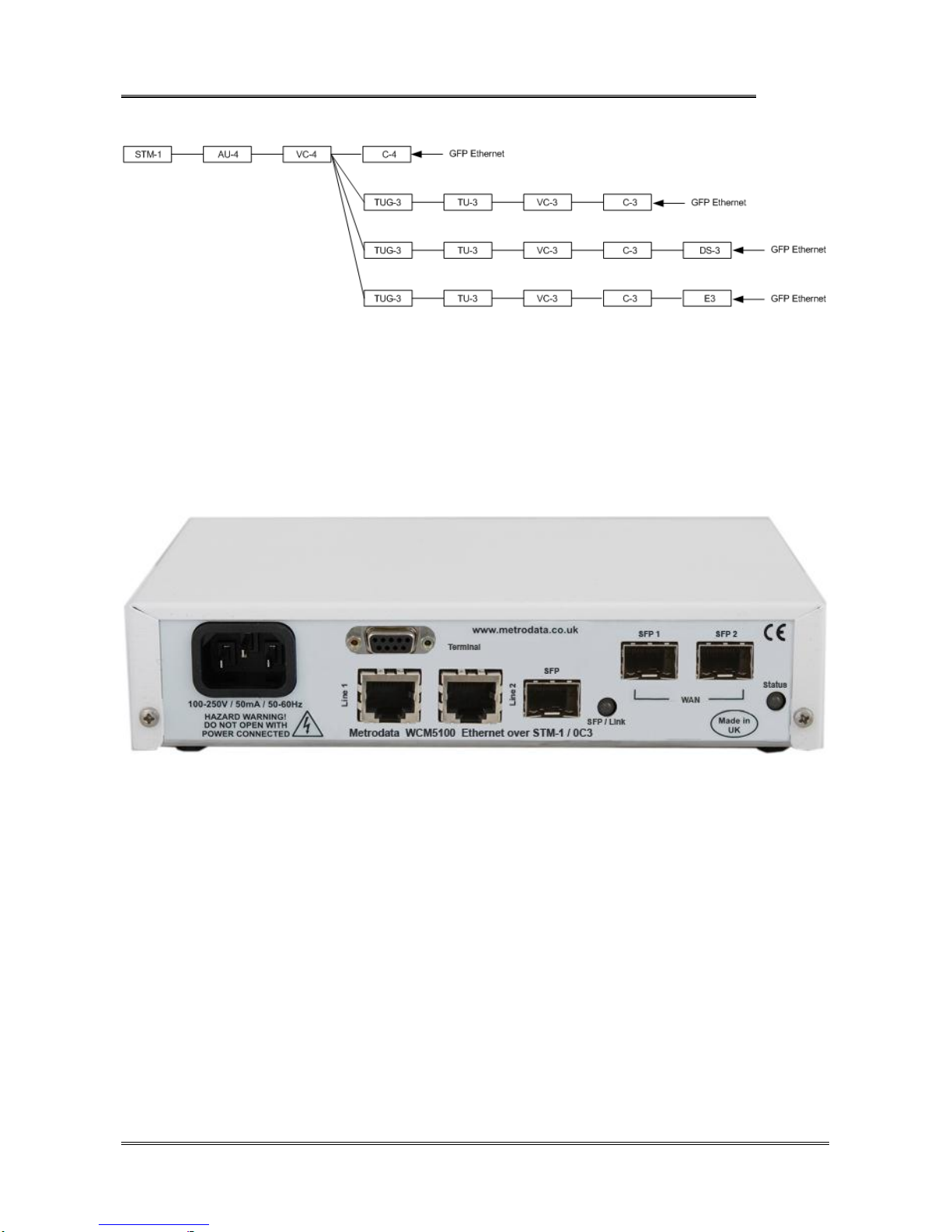
The WCM5100 performs GFP frame encapsulation and supports the VC-4 and VC-3 EoS (
Ethernet over Sonet ) modes. Internal packet buffers enable the WCM5100 to smooth out
bursty traffic and prevent packet loss as the higher layer protocols rate adapt to the SDH
capacity.
METRODATA LTD WCM5100
User Manual
76-02-087 Rev G
11 of
134
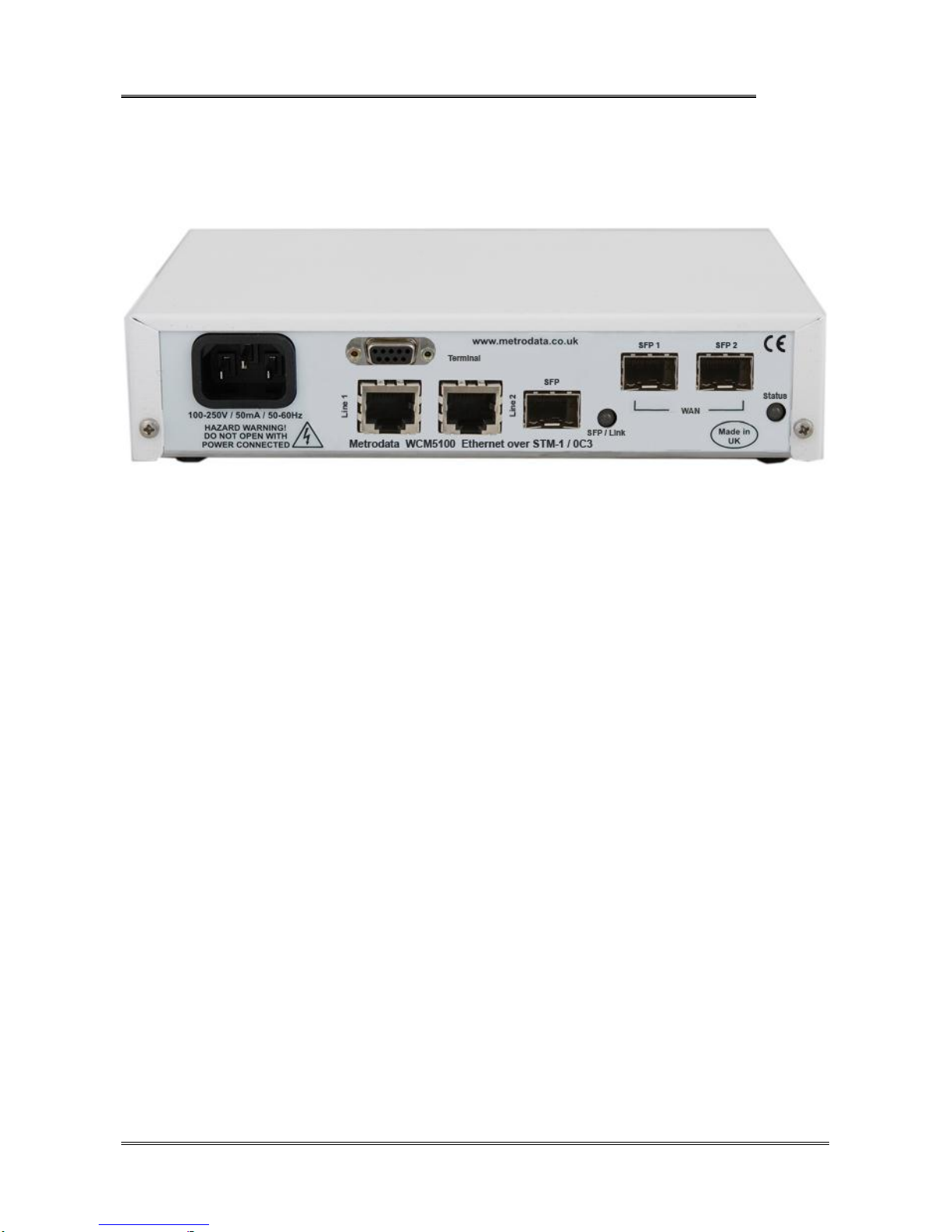
1.1 WCM5100 Rear Panel
The WCM5100 device is a compact unit, as shown below, occupying half a shelf in a
traditional 19inch rack. All power and data connectors and LED status indicators are
accessible from the rear of the unit.
1.2 Safety
The WCM5100 must not be connected to cabling which would be required by BS6701 to
equipped with over voltage protection. The following ports on the WCM5100 are
designated SELV ( Safety Extra Low Voltage ) within the scope of EN41003
Terminal Port 9 Way D-Type
LAN Port(s) RJ45 10/100/1000BaseT
SFP
These ports must only be connected to SELV ports on other equipment in accordance with
EN60950 clause 2.3

METRODATA LTD WCM5100
User Manual
76-02-087 Rev G
12 of
134
1.3 Electro Magnetic Compatibility
In order to ensure EMC compliance, all signal and data cables must be shielded and use
screened connector shells. The cable screens must be terminated to the screened
connector shell and not connected to any pins of the connector. Failure to use the correct
connectors may compromise EMC compliance.
1.3.1 EN55022 Statement
The WCM5100 is a Class A product. In a domestic environment, this product may cause
radio interference, in which case the user will be required to take adequate measures.
1.3.2 FCC Declaration
This equipment has been tested and found to comply with the limits of the Class A digital
device, pursuant to Part 15 of the FCC rules. These limits are designed to provide
reasonable protection against harmful interference when the equipment is operated in a
commercial environment. This equipment generates, uses and can radiate radio frequency
energy and, if not installed and used in accordance with the Installation and Operation
manual, may cause harmful interference to the radio communications. Operation of this
equipment in a residential area is likely to cause harmful interference in which case the
user will be required to correct the interference at his own expense.
1.4 WEEE Directive
The WCM5100 is covered by Directive 2002/96/EC ( OJ:L37/24/2003 ) on Waste Electrical
and Electronic Equipment ( WEEE ) Units must therefore not be disposed of in standard
landfill.
1.5 RoHS Compliance
The WCM5100 is compliant with the EU RoHS Directive 2002/95/EC. The RoHS directive
bans the use of six hazardous materials in products placed on the market after July 1st
2006. The six banned materials are Lead, Mercury, Hexavalent Chromium,
Polybrominated Biphenys, Polybrominated Diphenyl Ethers and Cadmium.
The WCM5100 is manufactured using a lead free soldering process and as such is fully
RoHS 6/6 compliant.
METRODATA LTD WCM5100
User Manual
76-02-087 Rev G
13 of
134
2 INSTALLATION
2.1 WCM5100 Rear Panel
The WCM5100 is available with either AC Mains or DC power options.
2.1.1 Mains Power
The WCM5100 has an internal power supply and is supplied via an IEC mains power
socket. The WCM5100 operates over the wide range 100 to 250V AC and draws less
than 6 watts.
2.1.2 DC Power
The WCM5100 is available with an internal DC power supply with two variants available,
DC -48V ( 36 to 72V DC )
DC 24V ( 7 to 36V DC )
DC powered units have an external earth stud which must be securely connected to an
earth connection to ensure EMC compliance.

METRODATA LTD WCM5100
User Manual
76-02-087 Rev G
14 of
134
2.2 Base Label and Bit Switches
On the underside of the WCM5100 unit there are bit switches which may be used to
configure certain functions within the unit. The bit switches are used to configure the
default settings following a cold start.
2.2.1 WCM5100 Base Label
2.2.2 Bit Switches
The bit switches are used to configure the default settings following a cold start, either
from the console, or by powering on with switch 8 in the OFF position.
2.2.2.1 Bit switch 1, Boot Mode 0
This bit switch is used to determine whether the IP proxy management mode is enabled or
not. IP proxy mode utilises OAM to remotely manage a WCM5100 device.
ON Proxy Mode Disabled
OFF Proxy Mode Enabled,

METRODATA LTD WCM5100
User Manual
76-02-087 Rev G
15 of
134
2.2.2.2 Bit switch 2, Boot Mode 1
This bit switch is ignored if Proxy Mode is disabled. When Proxy mode is enabled, this
switch setting determines whether the unit acts as Master/Server, or Slave/Client.
ON Proxy Mode, Server
OFF Proxy Mode, Client
2.2.2.3 Bit switch 3, DHCP
This bit switch enables DHCP for IP address allocation.
ON DHCP Disabled
OFF DHCP Enabled
2.2.2.4 Bit switch 4, Framing
This bit switch determines the operating mode of the SDH WAN interface.
ON SONET OC-3
OFF SDH STM-1
This bit switch is currently unused on the WCM5100 which does not offer SONET
operation.
2.2.2.5 Bit switch 5, Timing Mode
This bit switch determines the timing source for the SDH WAN interface
ON Internal Timing
OFF Loop Timing
Note, it is vital that one end of SDH WAN link is set to internal, as loop/loop will give an
unstable system.

METRODATA LTD WCM5100
User Manual
76-02-087 Rev G
16 of
134
2.2.2.6 Bit switch 6,Unused
This bit switch is unused on the WCM5100,
2.2.2.7 Bit switch 7, SFP Mode
This bit switch is used to force the configuration of the SFP interface to match the SFP
type inserted.
ON 1000Base-X SFP
OFF 100Base-FX SFP
2.2.2.8 Bit switch 8, Factory Default
This bit switch will clear the stored configuration and return the unit to the default settings
as defined by the bit switches.
ON Normal Operation
OFF Factory Cold Start, load default settings
The main use of this switch it to ensure a unit can be accessed in the event that the
password has been lost.
METRODATA LTD WCM5100
User Manual
76-02-087 Rev G
17 of
134
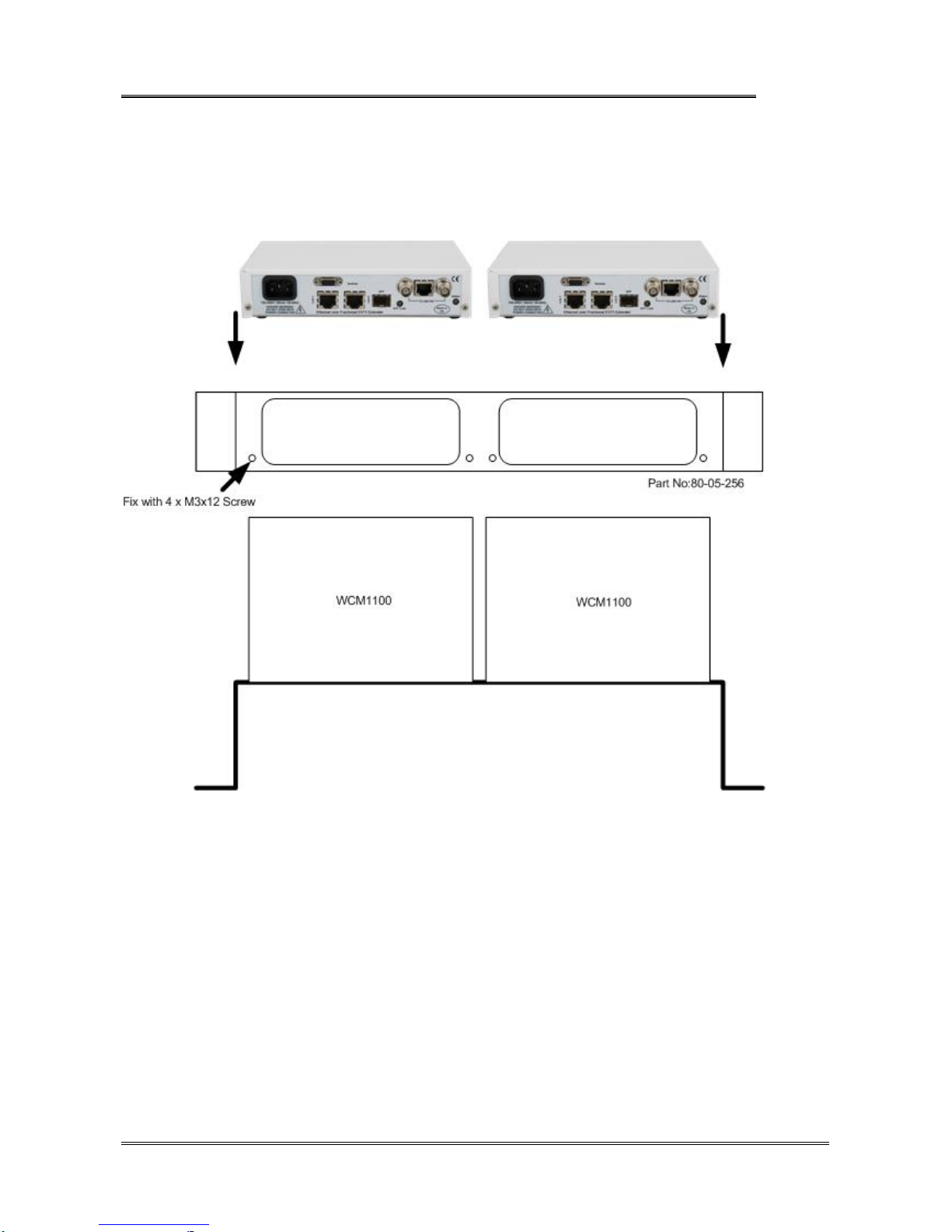
2.3 Rackmounting
The WCM5100 is a standalone, desktop unit however it may be mounted in a standard 19
inch rack using the rack mounting kit, part number 80-05-256.
To mount the WCM5100 in the 19 inch rack mount adaptor first remove the two M3x12
screws and washers from the rear panel of the unit. Then align the WCM5100 rear panel
with the mounting bracket, and secure the unit to the adaptor using the previously
removed screws.
When rack mounting, please ensure that the bit switches on the underside are correctly
configured prior to mounting the units in the rack.
METRODATA LTD WCM5100
User Manual
76-02-087 Rev G
18 of
134
3 WCM5100 APPLICATIONS
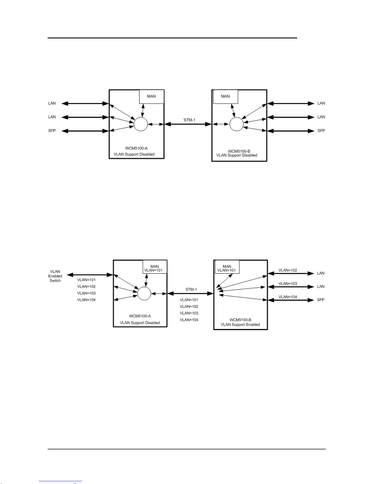
3.1 WCM5100 Normal Mode
In this application, the WCM5100 is operating with Traffic Isolation Disabled. In this mode,
the WCM5100 acts as a simple, layer 2, 5 port switch with packetsswitched based on MAC
address alone. The WCM5100 supports both local and remote switching, and forwarding
over the WAN trunk.
Management traffic is not isolated from the through data traffic, and both units may be
managed from any port.
3.2 WCM5100 VLAN Trunk Mode
In this application, WCM-A is connected to a VLAN enabled LAN switch. The LAN switch
is configured as a VLAN trunk and all packets are tagged with VLAN Tags. WCM-A is
operating with VLAN support enabled but all ports defined as Trunks. A VLAN ID is
allocated to the Manager and thus management traffic is isolated from the user traffic and
the management VLAN, in this case 101, can be used to manage the WCM’s. WCM1100-
B is configured with VLAN support enabled but each port is configured as an access port
and isolated to a single VLAN.
Trunk ports expect packets to be tagged, whilst access ports expect untagged packets and
will add tag and priority to incoming packets.

METRODATA LTD WCM5100
User Manual
76-02-087 Rev G
19 of
134
3.3 VLAN Mode
In this mode, both WCM units have VLAN support enabled, and all ports are defined as
access ports VLAN 101 is used as the management VLAN and in unit WCM-A the VLAN
group 101 includes the LAN Port 1, the Manager and the SDH WAN port. At the remote
end, The SFP port is disabled to prevent customer access to the WCM manager.
3.4 S-Tag Mode
In this mode, the WCM adds a, port based, S-TAG to all incoming traffic. Where customer
traffic is already VLAN tagged, this leads to double tagging or ‘QinQ’operation. The use
of the S-TAG enables the carrier to isolate customer traffic. Carrier management traffic is
carried with a separate S-Tag giving management access to both units, and on the
customer site the external management access is disabled.

METRODATA LTD WCM5100
User Manual
76-02-087 Rev G
20 of
134
4 QUICK START CONFIGURATION
The following guide gives a simple, quick start introduction to configuring the WCM5100
for Normal Mode operation as shown in section 2.1
4.1 Cold Start the Unit
When a WCM5100 is shipped from the factory it will be in the default condition, however
with previously used equipment this may not be the case. To return the unit to the default
state will require a power cycle and configuration of the bit switches.
The underside of the unit has a set of accessible bit switches and a label, as shown below
for the two products:
Ensure all other bit switches are in the desired default positions.
To cold start the unit, first set bit switch 8 (Cold Start) to the OFF (Return to Default
Settings) position. Power up the WCM5100, wait for the Status LED to come on in any
state, and then power down. To return to normal mode, return bit switch 8 to the ON
(Normal Operation) position.
4.2 Access the WCM
Initial access to the WCM5100 is made using the Terminal Port on the rear panel of the
unit. The Terminal port defaults to 19200baud, 8bit, No Parity, 1 Stop Bit. The 9 Way D-
Type is configured as a DCE port with standard pin out as shown below:
P
in
Direction
Signal
1 out DCD
2 out RXD*
3 In TXD*
4 In DTR
5 Signal Ground*
6 out DSR
7 In RTS
8 out CTS
9 no connect
Figure 3.3 Terminal Port Connector Pin Configuration
Other manuals for WCM5100
3
Table of contents
Other Metrodata Extender manuals

Metrodata
Metrodata MetroCONNECT WCM-Serial User manual

Metrodata
Metrodata WCM5100 User manual

Metrodata
Metrodata WCM5100 User manual

Metrodata
Metrodata WCM1100 User manual

Metrodata
Metrodata WCM5100 User manual

Metrodata
Metrodata WAN-in-a-CAN WC3445 User manual

Metrodata
Metrodata WCM1100 User manual

Metrodata
Metrodata WCM1400 BNC User manual


