Metrohm 872 User manual

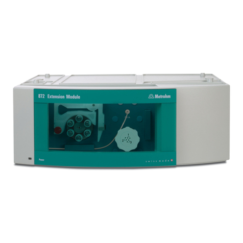
872 Extension Module
Liquid handling – 2.872.0060
Manual
8.872.8003EN


Metrohm AG
CH-9101 Herisau
Switzerland
Phone +41 71 353 85 85
Fax +41 71 353 89 01
www.metrohm.com
872 Extension Module
Liquid handling – 2.872.0060
Manual
8.872.8003EN 06. 2009 zst

Teachware
Metrohm AG
CH-9101 Herisau
This documentation is protected by copyright. All rights reserved.
Although all the information given in this documentation has been
checked with great care, errors cannot be entirely excluded. Should you
notice any mistakes please send us your comments using the address
given above.

■■■■■■■■■■■■■■■■■■■■■■ Table of contents
872 Extension Module – Liquid handling ■■■■■■■■ III
Table of contents
1 Introduction 1
1.1 Instrument description ......................................................... 1
1.2 Intended use ......................................................................... 2
1.3 About the documentation ................................................... 2
1.3.1 Content and scope .................................................................. 2
1.3.2 Symbols and conventions ........................................................ 2
1.4 Safety instructions ................................................................ 3
1.4.1 General notes on safety ........................................................... 3
1.4.2 Electrical safety ........................................................................ 3
1.4.3 Tubing and capillary connections ............................................. 4
1.4.4 Flammable solvents and chemicals ........................................... 4
1.4.5 Recycling and disposal ............................................................. 4
2 Overview of the instrument 5
2.1 Front ...................................................................................... 5
2.2 Rear ........................................................................................ 5
3 Functioning 6
3.1 10-port valve ......................................................................... 6
3.2 Transfer tubing ..................................................................... 8
3.3 Mixing vessel ......................................................................... 9
3.4 Peristaltic pump and injection valve ................................. 10
4 Assembly 12
4.1 General ................................................................................ 12
4.2 Mounting the extension module onto the IC instru-
ment ..................................................................................... 13
4.3 Mounting the extension module below the IC instru-
ment ..................................................................................... 16
4.4 Setting up the extension module next to the IC instru-
ment ..................................................................................... 19
4.5 Mounting the accessories .................................................. 23
5 Installation 26
5.1 About this chapter .............................................................. 26
5.2 Installation overview .......................................................... 26
5.3 Installation diagram .......................................................... 27

Table of contents ■■■■■■■■■■■■■■■■■■■■■■
IV ■■■■■■■■ 872 Extension Module – Liquid handling
5.4 10-port valve ....................................................................... 28
5.4.1 Connecting the 10-port valve ................................................ 28
5.5 Peristaltic pump .................................................................. 29
5.5.1 Principle of the peristaltic pump ............................................. 29
5.5.2 Installing the peristaltic pump ................................................ 30
5.6 Injection valve ..................................................................... 34
5.6.1 Connecting the injection valve ............................................... 34
5.6.2 Mode of operation of the injection valve ............................... 35
6 Start-up 37
7 Operation and maintenance 38
7.1 General information ........................................................... 38
7.1.1 Care ...................................................................................... 38
7.1.2 Maintenance by Metrohm Service .......................................... 38
7.1.3 Operation .............................................................................. 38
7.1.4 Shutting down ...................................................................... 39
7.2 Door ..................................................................................... 39
7.3 Peristaltic pump .................................................................. 39
7.3.1 Operation .............................................................................. 39
7.3.2 Maintenance ......................................................................... 40
7.4 Quality Management and validation with Metrohm ....... 42
8 Troubleshooting 43
8.1 Problems and their solutions ............................................. 43
9 Technical specifications 44
9.1 Reference conditions .......................................................... 44
9.2 Instrument ........................................................................... 44
9.3 Ambient conditions ............................................................ 44
9.4 Housing ............................................................................... 45
9.5 10-port valve ....................................................................... 45
9.6 Peristaltic pump .................................................................. 45
9.7 Injection valve ..................................................................... 46
9.8 Interfaces ............................................................................. 46
9.9 Safety specification ............................................................ 46
9.10 Electromagnetic compatibility (EMC) ................................ 46
9.11 Weight ................................................................................. 46
10 Conformity and warranty 47
10.1 Declaration of Conformity ................................................. 47

■■■■■■■■■■■■■■■■■■■■■■ Table of contents
872 Extension Module – Liquid handling ■■■■■■■■ V
10.2 Quality Management Principles ........................................ 48
10.3 Warranty (guarantee) ......................................................... 49
11 Accessories 50
11.1 Scope of delivery ................................................................ 50
11.2 Optional accessories ........................................................... 53
Index 56

Table of figures ■■■■■■■■■■■■■■■■■■■■■■
VI ■■■■■■■■ 872 Extension Module – Liquid handling
Table of figures
Figure 1 Front 872 Extension Module – Liquid handling .................................. 5
Figure 2 Rear 872 Extension Module – Liquid handling ................................... 5
Figure 3 10-port valve – positions ................................................................... 6
Figure 4 Valve switchover, normal and with secured position .......................... 7
Figure 5 6.1562.160 transfer tubing ............................................................... 8
Figure 6 6.2762.000 mixing vessel with cover ................................................. 9
Figure 7 Measuring volume – Filling the sample loop .................................... 10
Figure 8 Measuring volume – Aspirating sample segment ............................. 11
Figure 9 Setup versions ................................................................................. 13
Figure 10 Dismounting the bottle holder ......................................................... 14
Figure 11 Mounting the bottle holder ............................................................. 15
Figure 12 Removing the base tray ................................................................... 17
Figure 13 Mounting the base tray ................................................................... 18
Figure 14 Mounting the base tray ................................................................... 20
Figure 15 Mounting the bottle holder ............................................................. 21
Figure 16 Connecting the drainage tubings ..................................................... 22
Figure 17 Installation diagram ......................................................................... 27
Figure 18 Peristaltic pump ............................................................................... 29
Figure 19 Installing the pump tubing .............................................................. 30
Figure 20 Install pump tubing connection with filter ....................................... 31
Figure 21 Install pump tubing connection without filter .................................. 32
Figure 22 Injection valve - Measuring volume .................................................. 34
Figure 23 Injection valve – Positions ................................................................ 35
Figure 24 Pump tubing connection – Changing the filter ................................. 41

■■■■■■■■■■■■■■■■■■■■■■ 1 Introduction
872 Extension Module – Liquid handling ■■■■■■■■ 1
1 Introduction
1.1 Instrument description
Existing 850 Professional IC instruments can be expanded to include addi-
tional functions by means of extension modules. Every 850 Professional IC
instrument can be supplemented with up to 3 extension modules.
The 872 Extension Module – Liquid handling extends the possibilities
of inline sample preparation and liquid handling. Up to six auxiliary solu-
tions can be provided in the instrument. A mixing vessel that can be
mounted on the instrument allows the mixing of different solutions. The
872 Extension Module – Liquid handling makes guard column reactions
and pH adjustments possible - and much more.
The extension module is operated with MagIC Net software, just like the
IC instrument. When it is connected to an 850 Professional IC instrument,
MagIC Net recognizes the extension module automatically and checks its
functional capability. It controls and monitors the IC instrument as well as
the extension module, evaluates the measured data and administers it in a
database.
The 872 Extension Module – Liquid handling comprises the following
components:
10-port valve
The 10-port valve is utilized for sample preparation and serves as a switch-
over point between different liquids.
Peristaltic pump
The Peristaltic pump is used for pumping sample and auxiliary solutions. It
can rotate in both directions.
Injection valve
In Liquid Handling the injection valve is used for the measurement of pre-
cisely defined smaller volumes. The liquid is measured in the sample loop
and injected into the sample preparation process by means of valve
switchover.

1.2 Intended use ■■■■■■■■■■■■■■■■■■■■■■
2■■■■■■■■ 872 Extension Module – Liquid handling
1.2 Intended use
With the 872 Extension Module – Liquid handling, an 850 Profes-
sional IC instrument can be extended to include a broad range of addi-
tional sample preparation possibilities without having to modify the instru-
ment in between. For example calibration, ion exchange, guard column
reactions or a combination of several of them.
The present instrument is suitable for processing chemicals and flammable
samples. The usage of the 872 Extension Module therefore requires that
the user has basic knowledge and experience in the handling of toxic and
caustic substances. Knowledge with respect to the application of the fire
prevention measures prescribed for laboratories is also mandatory.
1.3 About the documentation
1.3.1 Content and scope
This document describes the 872 Extension Module – Liquid han-
dling, its assembly and connection to the IC instrument, as well as the
installation, operation and maintenance of the individual components.
Technical specifications, troubleshooting and information concerning
scope of delivery and optional accessories makes up the rest of the man-
ual.
This document does not on the other hand describe the functions of the
IC instrument - extension module unit, nor does it describe the capillary
connections that proceed from the extension module. For this purpose,
please refer to the manual for the IC instrument and that for the sample
processor.
Additional information concerning the configuration of MagIC Net can be
found on the online help for MagIC Net.
1.3.2 Symbols and conventions
The following symbols and styles are used in this documentation:
Cross-reference to figure legend
The first number refers to the figure number, the
second to the instrument part in the figure.
Instruction step
Carry out these steps in the sequence shown.

■■■■■■■■■■■■■■■■■■■■■■ 1 Introduction
872 Extension Module – Liquid handling ■■■■■■■■ 3
Warning
This symbol draws attention to a possible life hazard
or risk of injury.
Warning
This symbol draws attention to a possible hazard due
to electrical current.
Warning
This symbol draws attention to a possible hazard due
to heat or hot instrument parts.
Warning
This symbol draws attention to a possible biological
hazard.
Caution
This symbol draws attention to a possible damage of
instruments or instrument parts.
Note
This symbol marks additional information and tips.
1.4 Safety instructions
1.4.1 General notes on safety
WARNING
This instrument may only be operated in accordance with the specifica-
tions in this documentation.
This instrument has left the factory in a flawless state in terms of technical
safety. To maintain this state and ensure non-hazardous operation of the
instrument, the following instructions must be observed carefully.
1.4.2 Electrical safety
The electrical safety when working with the instrument is ensured as part
of the international standard IEC 61010.
WARNING
Only personnel qualified by Metrohm are authorized to carry out service
work on electronic components.

1.4 Safety instructions ■■■■■■■■■■■■■■■■■■■■■■
4■■■■■■■■ 872 Extension Module – Liquid handling
WARNING
Never open the housing of the instrument. The instrument could be
damaged by this. There is also a risk of serious injury if live components
are touched.
There are no parts inside the housing which can be serviced or replaced
by the user.
1.4.3 Tubing and capillary connections
CAUTION
Leaks in tubing and capillary connections are a safety risk. Tighten all
connections well by hand. Avoid applying excessive force to tubing
connections. Damaged tubing ends lead to leakage. Appropriate tools
can be used to loosen connections.
Check the connections regularly for leakage. If the instrument is used
mainly in unattended operation, then weekly inspections are manda-
tory.
1.4.4 Flammable solvents and chemicals
WARNING
All relevant safety measures are to be observed when working with
flammable solvents and chemicals.
■Set up the instrument in a well-ventilated location (e.g. laboratory
flue).
■Keep all sources of flame far from the workplace.
■Clean up spilled fluids and solids immediately.
■Follow the safety instructions of the chemical manufacturer.
1.4.5 Recycling and disposal
This product is covered by European Directive 2002/96/EC, WEEE – Waste
from Electrical and Electronic Equipment.
The correct disposal of your old equipment will help to prevent negative
effects on the environment and public health.
More details about the disposal of your old equipment can be obtained
from your local authorities, from waste disposal companies or from your
local dealer.

■■■■■■■■■■■■■■■■■■■■■■ 2 Overview of the instrument
872 Extension Module – Liquid handling ■■■■■■■■ 5
2 Overview of the instrument
2.1 Front
1 2 34
Figure 1 Front 872 Extension Module – Liquid handling
1Standby indicator 2Peristaltic pump
310-port valve 4Injection valve
2.2 Rear
In Out
Made by Metrohm Herisau Switzerland
12
Figure 2 Rear 872 Extension Module – Liquid handling
1Connector In
To connect the extension module to the IC
instrument or to another previously connec-
ted extension module.
2Connector Out
To connect an additional extension module.

3.1 10-port valve ■■■■■■■■■■■■■■■■■■■■■■
6■■■■■■■■ 872 Extension Module – Liquid handling
3 Functioning
3.1 10-port valve
The 10-port valve is used for sample preparation. For this, the central posi-
tion (3-11) can be connected to the 10 other positions, one after the
other, by means of the selector (3-13).
The transfer tubing is connected to the central position. Liquids can be
aspirated into the transfer tubing by one of the 10 positions with the aid
of a Dosino and then transported to any other position by reversing the
flow.
The following illustration shows a 10-port valve with a possible utilization
of the positions:
1
2
3
4
5
6
7
8
9
10
11
12
13
Figure 3 10-port valve – positions
1Position 1
Connector for the connection to e.g. the
injection valve in the extension module.
2Position 2
Connector for the connection to e.g. the
injection valve in the IC instrument.
3Position 3
Connector for the connection to e.g. the
mixing vessel.
4Position 4
Connector for the connection to an auxiliary
solution.
5Position 5
Connector for the connection to an auxiliary
solution.
6Position 6
Connector for the connection to an auxiliary
solution.
7Position 7
Connector for the connection to an auxiliary
solution.
8Position 8
Connector for the connection to e.g. the
waste container.
9Position 9
Connector for the connection to an auxiliary
solution.
10 Position 10
Connector for the connection to e.g. the ion
exchanger.

■■■■■■■■■■■■■■■■■■■■■■ 3 Functioning
872 Extension Module – Liquid handling ■■■■■■■■ 7
11 Central position
Connector connected with the transfer tub-
ing.
12 10-port valve
13 Selector
Can be rotated for selecting the active posi-
tion.
The selector can rotate in a clockwise or counterclockwise direction. Nor-
mally, the shortest path is selected when switching over to a new posi-
tion.
1
2
3
4
5
6
7
8
9
10
Secured positions
In order to avoid contaminations, any given position can be defined as
"secured". The secured position is moved to during switching only if it is
the goal of the switching procedure.
If the secured position lies along the shortest route during a valve switch-
over, then the longer path will automatically be selected.
Example: Switching from position 2 to position 5.
The shorter path travels via positions 3 and 4 (see illustration 4, left). If
however position 4 is defined as the secured position, then the 10-port
valve will automatically switch via the connectors 1 – 10 – 9 – 8 – 7 – 6
(see illustration 4, left).
X
1
2
3
4
5
6
7
8
9
10
1
2
3
4
5
6
7
8
9
10
Figure 4 Valve switchover, normal and with secured position

3.2 Transfer tubing ■■■■■■■■■■■■■■■■■■■■■■
8■■■■■■■■ 872 Extension Module – Liquid handling
3.2 Transfer tubing
The transfer tubing – a long coiled tubing (V=15 mL) – is used both for
"storing" various liquids and in order not to contaminate the Dosino with
these liquids. These liquid segments can be separated from one another
with air bubbles or water. With its pedestal (5-3), the transfer tubing can
be placed in one of the recesses of the bottle holder.
1
2
3
Figure 5 6.1562.160 transfer tubing
1Connector to the Dosino 2Connector to the 10-port valve
3Pedestal
For placing into the 6.2057.200 bottle
holder.
The transfer tubing is connected by means of a connector (5-2) with the
central position of the 10-port valve and by means of another connector
(5-1) with a Dosino.
The Dosino is responsible for the transport and dosing of the liquids and is
filled with a transfer solution (usually water). It can move defined volumes
of liquids in two directions: aspirate and eject.
■During aspiration, the liquid is suctioned out of the active position of
the 10-port valve through the central position and into the transfer
tubing.
■During ejection, the liquid that has collected in the transfer tubing is
transported through the central position of the 10-port valve and from
there to the active position.

■■■■■■■■■■■■■■■■■■■■■■ 3 Functioning
872 Extension Module – Liquid handling ■■■■■■■■ 9
3.3 Mixing vessel
The mixing vessel is connected with the 10-port valve, e.g. through posi-
tion 3. Various liquids can be mixed in the mixing vessel. This takes place
either by means of rapid injection of the liquids to be mixed or by the
introduction of air bubbles. The homogenized liquid can be transported
onward through the 10-port valve.
1
2
3
Figure 6 6.2762.000 mixing vessel with cover
1Cover for the 6.2762.010 mixing vessel
With two connector openings.
26.2762.000 mixing vessel
Can be put on the 6.2057.200 bottle holder.
3Connector
For the 10-port valve.
Like the other Metrohm sample vessels, the mixing vessel is made of poly-
propylene PP. It has an extremely smooth surface which permits no drop
formation. The mixing vessel can be readily rinsed out and dried. It can be
used for anions as well as for cations.

3.4 Peristaltic pump and injection valve ■■■■■■■■■■■■■■■■■■■■■■
10 ■■■■■■■■ 872 Extension Module – Liquid handling
3.4 Peristaltic pump and injection valve
The peristaltic pump and the injection valve are utilized for the precise
measurement of small volumes.
The liquid to be dosed, e.g. sample (7-1), is pumped with the peristaltic
pump (7-2) through the sample loop (7-4) on the injection valve (7-3).
The desired volume is defined precisely by the size of the selected sample
loop.
1
2
3
4
5
6
9
10
7
8
123
4
Figure 7 Measuring volume – Filling the sample loop
1Sample 2Peristaltic pump
3Injection valve 4Sample loop
Following the switchover of the valve (8-2), the measured sample seg-
ment (8-5) is conveyed by aspiration with the Dosino (8-1) through the
10-port valve (8-4) into the transfer tubing (8-6), from where it can be
conveyed onward to a different outlet.

■■■■■■■■■■■■■■■■■■■■■■ 3 Functioning
872 Extension Module – Liquid handling ■■■■■■■■ 11
1
2
3
4
5
6
9
10
7
8
1
2
3
4
5
6
Figure 8 Measuring volume – Aspirating sample segment
1Dosino 2Injection valve
3Container with transfer solution 410-port valve
5Sample 6Transfer tubing

4.1 General ■■■■■■■■■■■■■■■■■■■■■■
12 ■■■■■■■■ 872 Extension Module – Liquid handling
4 Assembly
4.1 General
The extension modules are fitted directly to the 850 Professional IC instru-
ment and connected with it via 6.2156.060 connection cable. Extension
modules have no power supply of their own, but rather draw the electric-
ity they require from the instrument with which they are connected.
Up to three extension modules can be connected to an 850 Professional
IC instrument. The following restrictions are to be taken into account:
Restrictions The 850 Professional IC instruments and their extension modules must not
have more than 4 identical components in common, i.e.:
■a maximum of 4 high pressure pumps,
■a maximum of 4 peristaltic pumps,
■a maximum of 4 injection valves,
■a maximum of 4 suppressors (MSM, SPM incl.),
BUT
■only a maximum of 3 degassers
■and a maximum of 3 CO2 suppressors (MCS)
NOTE
If all 4 high pressure pumps are being used at once, then not all of
them are permitted to run at maximum flow for longer periods of time.
Extension modules can be mounted in the following setup versions:
■above, between instrument and bottle holder (9-A), or
■below, between instrument and base tray (9-B), or
■next to the instrument (9-C) with a separate 6.2061.110 base tray and
a 6.2061.100 bottle holder (to be ordered additionally). For this, the
longer 6.2156.070 connection cable (to be ordered additionally), is
necessary, too.
Other manuals for 872
3
This manual suits for next models
1
Table of contents
Other Metrohm Control Unit manuals
