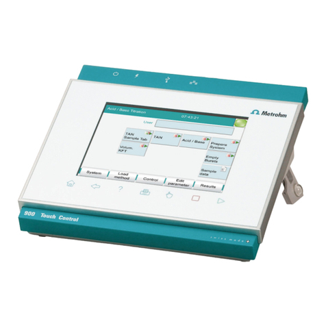
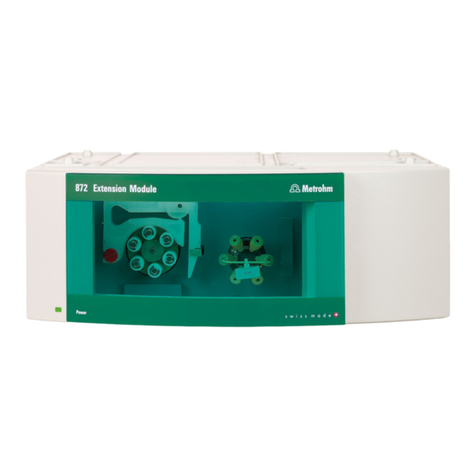
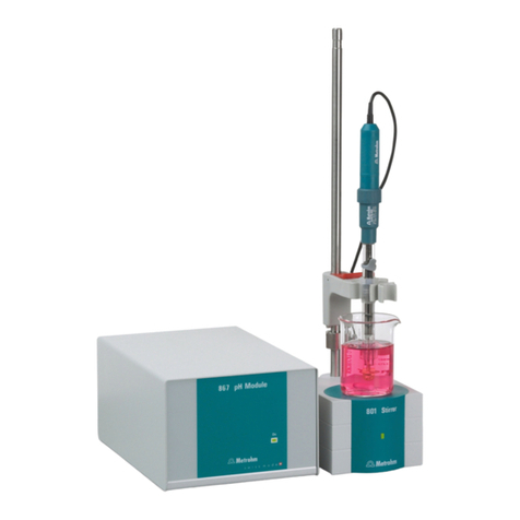
Metrohm OMNIS User manual

OMNIS Titration Module
Product manual
8.1002.8002EN / 2018-07-27


Metrohm AG
Ionenstrasse
CH-9100 Herisau
Switzerland
Phone +41 71 353 85 85
Fax +41 71 353 89 01
www.metrohm.com
OMNIS Titration Module
Product manual
8.1002.8002EN /
2018-07-27

Technical Communication
Metrohm AG
CH-9100 Herisau
This documentation is protected by copyright. All rights reserved.
This documentation has been prepared with great care. However, errors
can never be entirely ruled out. Please send comments regarding possible
errors to the address above.

■■■■■■■■■■■■■■■■■■■■■■ Table of contents
■■■■■■■■ III
Table of contents
1 Overview 1
1.1 OMNIS Titration Module – Product description ................. 1
1.2 OMNIS Titration Module – Product versions ...................... 1
1.3 About the documentation ................................................... 2
1.4 Additional information ......................................................... 3
1.4.1 Accessories .............................................................................. 3
2 Safety 4
2.1 Product safety ....................................................................... 4
2.2 Hazard levels ......................................................................... 4
2.3 Warning symbols .................................................................. 5
2.4 Intended use ......................................................................... 6
2.5 Residual risks ........................................................................ 6
2.5.1 General dangers at the workplace ........................................... 6
2.5.2 Danger from electrical potential ............................................... 7
2.5.3 Danger from biological substances .......................................... 8
2.5.4 Danger from highly flammable substances ............................... 8
2.5.5 Danger from careless transport ................................................ 9
2.5.6 Danger from leakage ............................................................... 9
2.6 Responsibility of the operator ............................................. 9
2.7 Personnel requirement ....................................................... 10
3 Functional description 11
3.1 System overview ................................................................. 11
3.1.1 System – Signals .................................................................... 11
3.1.2 System – Interfaces ................................................................ 12
3.2 OMNIS Titration Module – Overview ................................ 13
3.2.1 Magnetic stirrer – Overview ................................................... 15
3.2.2 Magnetic stirrer with accessories – Overview ......................... 16
3.2.3 Dosing unit – Overview .......................................................... 17
3.2.4 Bottle unit – Overview ........................................................... 21
3.2.5 Measuring Module Analog – Overview .................................. 23
3.2.6 Measuring Module Digital – Overview ................................... 24
3.2.7 OMNIS product with a volumetric KF titration cell – Over-
view ...................................................................................... 25
3.3 OMNIS Titration Module - Function .................................. 26
3.3.1 Magnetic stirrer – Function .................................................... 26
3.3.2 Dosing unit – Function ........................................................... 26
3.3.3 Bottle unit – Function ............................................................ 27

Table of contents ■■■■■■■■■■■■■■■■■■■■■■
IV ■■■■■■■■
3.3.4 Measuring Module Analog – Functional description ............... 28
3.3.5 Measuring Module Digital – Functional description ................ 29
3.3.6 Karl Fischer titration cell – Function ........................................ 29
3.4 OMNIS Titration Module – Indicators ............................... 29
3.5 Magnetic stirrer – Indicators and controls ....................... 30
3.6 OMNIS Titration Module - Interfaces ............................... 31
3.7 Measuring Module Analog – Interfaces ........................... 32
3.8 Measuring Module Digital – Interfaces ............................ 33
4 Transport and storage 34
4.1 Checking the delivery ......................................................... 34
4.2 Storing the packaging ........................................................ 34
5 Installation 35
5.1 Installation by Metrohm .................................................... 35
5.2 Setting up the product ....................................................... 35
5.3 Mounting the cylinder unit ................................................ 36
5.4 Magnetic stirrer – Installing the accessories .................... 39
5.5 OMNIS system – Mounting the measuring module ......... 41
5.6 Measuring module – Plugging in the electrode cable ..... 43
5.7 OMNIS system – Mounting the electrode ........................ 44
5.8 OMNIS Titration Module – Mounting the volumetric
Karl Fischer titration cell .................................................... 47
5.9 OMNIS titration system – Mounting the bottle unit ....... 59
6 Initial start-up 61
6.1 Initial start-up by Metrohm ............................................... 61
7 Operation and control 62
7.1 Operation ............................................................................ 62
7.2 Refitting the cylinder unit .................................................. 62
7.2.1 Dismantling the cylinder unit ................................................. 62
7.2.2 Mounting the cylinder unit .................................................... 65
7.3 Magnetic stirrer – Operation ............................................. 68
7.3.1 Switching the stirrer on and off .............................................. 68
7.3.2 Setting the stirring rate .......................................................... 69
8 Maintenance 70
8.1 General maintenance ......................................................... 70
8.2 Maintenance agreement .................................................... 71

■■■■■■■■■■■■■■■■■■■■■■ Table of contents
■■■■■■■■ V
8.3 Cleaning the product .......................................................... 72
8.3.1 Cleaning the OMNIS Liquid Adapter ...................................... 73
8.3.2 Dosing unit – Maintaining ..................................................... 75
8.3.3 Disassembling the cylinder unit .............................................. 75
8.3.4 Cleaning the cylinder unit ...................................................... 80
8.3.5 Cylinder unit – Cleaning the electrical contacts ....................... 82
8.3.6 Assembling the cylinder unit .................................................. 83
9 Malfunctions and troubleshooting 88
9.1 Troubleshooting .................................................................. 88
10 Disposal 89
11 Technical specifications 90
11.1 Ambient conditions ............................................................ 90
11.2 OMNIS Titration Module – Energy supply ........................ 90
11.3 OMNIS Magnetic Stirrer – Energy supply ......................... 90
11.4 OMNIS Measuring Module – Energy supply ..................... 90
11.5 OMNIS Titration Module – Dimensions ............................ 90
11.6 OMNIS Magnetic Stirrer – Dimensions ............................. 91
11.7 OMNIS Measuring Module – Dimensions ......................... 91
11.8 OMNIS Titration Module – Housing .................................. 91
11.9 OMNIS Magnetic Stirrer – Housing ................................... 92
11.10 OMNIS Measuring Module – Housing .............................. 92
11.11 OMNIS Titration Module – Connectors specifications .... 93
11.12 OMNIS Measuring Module Digital – Connectors specifi-
cations ................................................................................. 93
11.13 OMNIS Titration Module – Display specifications ........... 93
11.14 OMNIS Measuring Module Digital – Display specifica-
tions ..................................................................................... 94
11.15 OMNIS Measuring Module Analog – Measuring specifi-
cations ................................................................................. 94
11.16 OMNIS Titration Module – Liquid Handling specifica-
tions ..................................................................................... 95
11.17 Magnetic stirrer – Stirrer specifications ............................ 96


■■■■■■■■■■■■■■■■■■■■■■ Overview
■■■■■■■■ 1
1 Overview
1.1 OMNIS Titration Module – Product description
The OMNIS Titration Module is a titration module that is controlled by an
OMNIS Titrator. The OMNIS Titration Module is equipped with the follow-
ing functional units:
■Two plug-in positions at which a maximum of two measuring modules
can be fitted.
■One dosing unit with interchangeable cylinder units.
■One integrated magnetic stirrer, depending on the product version.
1.2 OMNIS Titration Module – Product versions
The product is available in the following versions:
Table 1 Product versions
Art. no. Designation Version feature
2.1002.0010 OMNIS Titration Module Without magnetic stirrer
2.1002.0110 OMNIS Titration Module With integrated magnetic
stirrer
The required numbers for the customer service can be found on the type
plate (see example):
1(01) = External article number 2(21) = Serial number
3(240) = Metrohm article number

About the documentation ■■■■■■■■■■■■■■■■■■■■■■
2■■■■■■■■
NOTE
Information on the accessories for the respective product version can
be obtained either on the Internet at http://www.metrohm.com or
via your regional Metrohm representative.
1.3 About the documentation
NOTE
Please read through this documentation carefully before putting the
product into operation.
The documentation contains important information and warnings
which you must follow in order to ensure safe operation of the prod-
uct.
Symbols and conventions
The following icons and formatting may appear in this documentation:
Cross-reference to figure legend
The first number refers to the figure number, the sec-
ond to the product part in the figure.
Instruction step
Carry out these steps in the sequence shown.
Method Designations for names of parameters, menu items,
tabs and dialog windows in the software.
File ▶ New Menu or menu item
Work area /
Properties
Menu paths in order to arrive at a particular position
in the software.
[Next] Button or key

■■■■■■■■■■■■■■■■■■■■■■ Overview
■■■■■■■■ 3
1.4 Additional information
Additional information concerning the topic can be found:
■in the Software Help
■in the Metrohm information portal on the Internet https://
guide.metrohm.com
1.4.1 Accessories
Up-to-date information on the scope of delivery and optional accessories
for your product can be found on the Internet. You can download this
information using the article number as follows:
Downloading the accessories list
1Enter https://www.metrohm.com/ into your Internet browser.
2Enter the article number of the product (e.g. 2.1001.0010) into the
search field.
The search result is displayed.
3Click on the product.
Detailed information regarding the product is shown on various tabs.
4On the Included parts tab, click Download the PDF.
The PDF file with the accessories data is created.
NOTE
When you receive your new product, we recommend downloading
the accessories list from the Internet, printing it out and keeping it for
reference purposes.

Product safety ■■■■■■■■■■■■■■■■■■■■■■
4■■■■■■■■
2 Safety
2.1 Product safety
This product exhibited no flaws in terms of technical safety at the time it
left the factory. To preserve this status and ensure non-hazardous opera-
tion of the product, the following instructions must be observed carefully.
2.2 Hazard levels
The following warning messages indicate the severity of the danger and
its possible effects.
DANGER
Immediate danger of life
Irreversible injuries that will result in death.
Warns of dangerous situations or unsafe actions that will most cer-
tainly cause severe injuries or death.
Lists measures to avoid hazard.
WARNING
Severe health hazards
Serious injuries that could result in death.
Warns of dangerous situations or unsafe actions that could result in
serious injuries or death.
Lists measures to avoid hazard.

■■■■■■■■■■■■■■■■■■■■■■ Safety
■■■■■■■■ 5
CAUTION
Health hazards or severe property damage
Warns of dangerous situations or unsafe actions that could result in
moderate injuries or considerable property damage.
Lists measures to avoid hazard.
2.3 Warning symbols
Make sure that any additional hazard symbols are marked on the product
for your operation of the product.
The following warning symbols in the documentation and at hazard areas
of the product point out hazard potentials:
– Warning of a hazard area
NOTE
Warning symbol on the product
If this warning symbol is on the product, read the respective docu-
mentation prior to installation and initial start-up.
– Warning of electric shock from electrical potential
– Warning of danger of fire and explosion from highly flammable
substances and gases
– Warning of danger of poisoning and chemical burns from chemi-
cal hazardous substances
– Warning of danger of infection and poisoning from biological
hazardous substances
– Warning of risk of injury from high temperatures

Intended use ■■■■■■■■■■■■■■■■■■■■■■
6■■■■■■■■
– Warning of cut injuries from pieces of broken glass and/or sharp
edges
– Warning of risk of injury by laser radiation
– Warning of dangerous optical radiation
2.4 Intended use
Metrohm products are used for the analysis and handling of chemicals.
Usage therefore requires the user to have basic knowledge and experience
in handling chemicals. Knowledge regarding the application of fire preven-
tion measures prescribed for laboratories is also mandatory.
Adherence to this technical documentation and compliance with the
maintenance specifications make up an important part of intended use.
Any utilization in excess of or deviating from the intended use is regarded
as misuse.
Specifications regarding the operating values and limit values of individual
products are contained in the "Technical specifications" section, if relevant.
Exceeding and/or not observing the mentioned limit values during opera-
tion puts people and components at risk. The manufacturer assumes no
liability for damage due to non-observance of these limit values.
The EU declaration of conformity loses its validity if modifications are car-
ried out on the products and/or the components.
2.5 Residual risks
2.5.1 General dangers at the workplace
Generally, the regulations and provisions of the regulatory institutions and
authorities in the field of work apply.
The instructions regarding the following areas have to be followed when
using the products:
■Work safety
■Handling mechanical installations
■Handling electricity
■Handling hazardous and environmentally damaging substances
■Handling hazardous and environmentally damaging liquids
■Disposing hazardous and environmentally damaging substances
If they are not followed, this may result in:

■■■■■■■■■■■■■■■■■■■■■■ Safety
■■■■■■■■ 7
■Disturbing, injuring and/or killing of people
■Malfunction and/or damage to instruments and infrastructure
■Damage and/or contamination of the environment
WARNING
General dangers at workplace
If the safety measures are not followed, working in a laboratory bears
a high risk of injury, which can endanger your life and health.
■Only professionally trained and qualified specialist personnel may
operate the products.
■Follow the applicable provisions concerning work safety and all
regulations on wearing protective clothing.
■Use suitable tools to perform your work.
■Check the fill level of waste bottles or waste canisters and analysis
vessels, and make sure they do not overflow.
■Use protective grounding when working with highly flammable
substances and gases.
2.5.2 Danger from electrical potential
WARNING
Electric shock from electrical potential
Risk of injury by touching live components or through moisture on
live parts.
■Never open the housing of the instrument.
■Protect live parts (e.g. power supply unit, power cord, connection
sockets) against moisture.
■If you suspect that moisture has gotten into the instrument, dis-
connect the instrument from the energy supply. Then notify Met-
rohm Service.
■Only personnel who have been issued Metrohm qualification may
perform service and repair work on electrical and electronic com-
ponents.

Residual risks ■■■■■■■■■■■■■■■■■■■■■■
8■■■■■■■■
2.5.3 Danger from biological substances
If the product is used for biological hazardous substances, it must be
marked in accordance with regulations.
In case of a return shipment to Metrohm or a Metrohm Service partner,
the product or product component has to be decontaminated and the
hazard symbol for biological hazardous substances must be removed. A
declaration of decontamination must be enclosed.
WARNING
Danger of infection and poisoning from biological hazardous
substances
Poisoning from toxins and/or infections from samples contaminated
with microorganisms.
■Clean and disinfect contaminated surfaces.
■Wear protective equipment.
■Use exhaust equipment when working with vaporizing hazardous
substances.
■Dispose of biologically contaminated substances properly.
2.5.4 Danger from highly flammable substances
WARNING
Danger of fire and explosion from highly flammable substances
and gases
Burns from fire and/or injuries from explosions.
■Avoid ignition sources.
■Use protective grounding.
■Use exhaust equipment.

■■■■■■■■■■■■■■■■■■■■■■ Safety
■■■■■■■■ 9
2.5.5 Danger from careless transport
WARNING
Risk of injury from careless transport
Injuries from spilled chemical and/or biological substances, falling
parts and pieces of broken glass.
■Remove loose parts (e.g. sample racks, sample beaker, bottles)
before transport.
■Remove liquids.
■Lift and transport the instrument with both hands on the base
plate.
■Lift and transport heavy instruments only according to instruc-
tions.
2.5.6 Danger from leakage
WARNING
Risk of injury by leakage
A risk of injury exists in connection with escaping liquids of leaking
parts and/or connection elements.
■Replace leaking parts and connection elements without delay.
■Tighten loose connecting elements.
■Use environmentally-friendly methods to dispose of escaping liq-
uids.
2.6 Responsibility of the operator
■Eliminate defects or damage which impair operating safety without
delay.
■Eliminate malfunctions which could impair safety without delay.
■The rules, regulations and instructions listed in the present document
are not the only valid ones. Comply with the applicable statutory rules,
government agency directives and regulations.
■Unauthorized modification of the products excludes any and all liability
on the part of the manufacturer for any damage resulting from this as
well as for any consequential damage. No modifications, attachments
or conversions which could impair safety may be carried out on the
products without the approval of the manufacturer.

Personnel requirement ■■■■■■■■■■■■■■■■■■■■■■
10 ■■■■■■■■
■Spare parts must meet the technical requirements established by the
manufacturer. Original spare parts always meet these requirements.
■Personnel must be familiar with this safety-relevant information and it
must be available for consultation at all times.
2.7 Personnel requirement
Only qualified personnel may operate the present product.
Qualified personnel are people authorized by the safety responsible to
carry out the necessary operations. They are capable of recognizing and
avoiding possible dangers. These people are qualified due to their profes-
sional training, experience and/or instruction. They know the relevant
standards, laws, provisions, accident prevention regulations and the com-
pany conditions.

■■■■■■■■■■■■■■■■■■■■■■ Functional description
■■■■■■■■ 11
3 Functional description
3.1 System overview
3.1.1 System – Signals
Visual signals
All products and components of the system that are equipped with multi-
color status displays indicate their respective status using colors and flash-
ing patterns.
The meaning of the colors and flashing patterns is explained in the follow-
ing table.
NOTE
Use of the flashing patterns
Not all products and components use all of the flashing patterns illus-
trated below.
However, the meaning of the flashing patterns is the same for all
products and components.
Signal Meaning
LED lights up yellow System start or initialization
LED flashes yellow (slowly) Ready for connection setup or
locking
LED flashes yellow (fast) Connection setup started or
locking underway
LED lights up green Ready for operation
LED flashes green (slowly) In operation
LED flashes red (fast) Malfunction or error

System overview ■■■■■■■■■■■■■■■■■■■■■■
12 ■■■■■■■■
3.1.2 System – Interfaces
The system provides the following interfaces:
Designation Abbrevia-
tion
Symbol Use
Metrohm Device Link MDL For connecting additional mod-
ules or products to a basic prod-
uct.
Human Interactive Device HID For connecting an external con-
trol product.
Metrohm Solution Identification MSI For connecting the OMNIS Liq-
uid Adapter.
Local Area Network LAN For connecting the product to a
local network.
USB connector USB For connecting USB devices.
Other manuals for OMNIS
1
Table of contents
Other Metrohm Control Unit manuals
Popular Control Unit manuals by other brands
Texas Instruments
Texas Instruments XIO2001 user guide
Metso
Metso NELDISC LW Series Installation maintenance and operating instructions
Pentair
Pentair FLECK 2750 Downflow Service manual
LCN
LCN ES7902 SEQ installation instructions
Cepex
Cepex PVC-U Series Installation and maintenance manual

Chargery
Chargery BMS16Pro Series manual
Conel
Conel CLEAR BOX operating instructions
Seneca
Seneca Z-8TC-LAB installation manual
Quectel
Quectel LG77L EVB user guide
Lawn Genie
Lawn Genie RJ Classic 54000 Installation and operating instructions
NXP Semiconductors
NXP Semiconductors Freescale TWR-WIFI-GS1500M Lab Guide
Supermicro
Supermicro MicroBlade MBI-6119M-C2 user manual
