Metrohm 940 Professional IC Vario ONE/ChS/LPG User manual

940 Professional IC Vario
940 Professional IC Vario ONE
Manual
8.940.8001EN /2017-07-31


Metrohm AG
CH-9100 Herisau
Switzerland
Phone +41 71 353 85 85
Fax +41 71 353 89 01
www.metrohm.com
940 Professional IC Vario
940 Professional IC Vario ONE
2.940.1100
Manual
8.940.8001EN /2017-07-31 zst

Technical Communication
Metrohm AG
CH-9100 Herisau
This documentation is protected by copyright. All rights reserved.
This documentation has been prepared with great care. However, errors
can never be entirely ruled out. Please send comments regarding possible
errors to the address above.

■■■■■■■■■■■■■■■■■■■■■■ Table of contents
940 Professional IC Vario ONE (2.940.1100) ■■■■■■■■ III
Table of contents
1 Introduction 1
1.1 Instrument description ......................................................... 1
1.2 Intended use ......................................................................... 3
1.3 Safety instructions ................................................................ 3
1.3.1 General notes on safety ........................................................... 3
1.3.2 Electrical safety ........................................................................ 3
1.3.3 Tubing and capillary connections ............................................. 4
1.3.4 Flammable solvents and chemicals ........................................... 5
1.3.5 Recycling and disposal ............................................................. 5
1.4 Symbols and conventions .................................................... 5
2 Overview of the instrument 7
2.1 Front ...................................................................................... 7
2.2 Rear ........................................................................................ 8
2.3 Feed-throughs for capillaries and cables .......................... 10
3 Installation 13
3.1 Setting up the instrument .................................................. 13
3.1.1 Packaging .............................................................................. 13
3.1.2 Checks .................................................................................. 13
3.1.3 Location ................................................................................ 13
3.2 Capillary connections in the IC system ............................. 13
3.3 Removing the handle ......................................................... 16
3.4 Removing transport locking screws .................................. 17
3.5 Connecting the drainage tubing and leak sensor ............ 18
3.5.1 Installing the drainage tubing ................................................ 18
3.5.2 Connecting the leak sensor .................................................... 20
3.6 Column thermostat ............................................................ 20
3.7 Connecting the eluent bottle ............................................. 21
3.8 Connecting the eluent degasser ........................................ 25
3.9 Installing the high-pressure pump .................................... 25
3.10 Installing an inline filter ..................................................... 26
3.11 Installing the pulsation absorber ...................................... 26
3.12 Injection valve ..................................................................... 27
3.13 Installing the conductivity detector .................................. 29
3.14 Installing the amperometric detector ............................... 30

Table of contents ■■■■■■■■■■■■■■■■■■■■■■
IV ■■■■■■■■ 940 Professional IC Vario ONE (2.940.1100)
3.15 Connecting the sample degasser (optional) ..................... 30
3.16 Connecting the instrument to a computer ....................... 32
3.17 Connecting the instrument to the power grid ................. 33
3.18 Initial start-up ..................................................................... 34
3.19 Connecting and rinsing the guard column ....................... 36
3.20 Connecting the separation column ................................... 38
3.21 Conditioning ........................................................................ 41
4 Operation 43
5 Operation and maintenance 44
5.1 IC system ............................................................................. 44
5.1.1 Operation .............................................................................. 44
5.1.2 Care ...................................................................................... 44
5.1.3 Maintenance by Metrohm Service .......................................... 44
5.1.4 Shutting down and recommissioning ..................................... 45
5.2 Capillary connections ......................................................... 46
5.3 Servicing the door .............................................................. 46
5.4 Column thermostat – Replacing the capillaries ............... 46
5.5 Handling the eluent ............................................................ 48
5.5.1 Manufacturing eluent ............................................................ 48
5.5.2 Changing the eluent .............................................................. 49
5.6 Servicing the eluent degasser ........................................... 49
5.7 Notes on operating the high-pressure pump ................... 50
5.8 Servicing the high-pressure pump .................................... 51
5.9 Servicing the inline filter .................................................... 64
5.10 Servicing the pulsation absorber ...................................... 67
5.11 Injection valve ..................................................................... 67
5.12 Servicing the detector ........................................................ 67
5.13 Rinsing the sample path .................................................... 67
5.14 Separation column ............................................................. 69
5.14.1 Separating efficiency .............................................................. 69
5.14.2 Protecting the separation column .......................................... 69
5.14.3 Storing the separation column ............................................... 69
5.14.4 Regenerating the separation column ...................................... 69
5.15 Quality management and qualification with Metrohm ... 70
6 Troubleshooting 71
6.1 ............................................................................................. 71

■■■■■■■■■■■■■■■■■■■■■■ Table of contents
940 Professional IC Vario ONE (2.940.1100) ■■■■■■■■ V
7 Technical specifications 75
7.1 Reference conditions .......................................................... 75
7.2 Instrument ........................................................................... 75
7.3 Ambient conditions ............................................................ 75
7.4 Housing ............................................................................... 76
7.5 Weight ................................................................................. 76
7.6 Leak sensor ......................................................................... 76
7.7 Column thermostat ............................................................ 76
7.8 Eluent degasser .................................................................. 77
7.9 High-pressure pump ........................................................... 77
7.10 Injection valve ..................................................................... 78
7.11 Detector ............................................................................... 78
7.12 Sample degasser ................................................................. 78
7.13 Power connection ............................................................... 78
7.14 Interfaces ............................................................................. 79
8 Accessories 80
Index 81

Table of figures ■■■■■■■■■■■■■■■■■■■■■■
VI ■■■■■■■■ 940 Professional IC Vario ONE (2.940.1100)
Table of figures
Figure 1 Front ................................................................................................. 7
Figure 2 Rear .................................................................................................. 8
Figure 3 Feed-throughs on the door .............................................................. 10
Figure 4 Openings for capillaries and cables .................................................. 11
Figure 5 Ducts for capillaries ......................................................................... 12
Figure 6 Removing the transport locking screws ............................................ 17
Figure 7 Installing the eluent bottle cap ........................................................ 21
Figure 8 Installing tubing weighting and aspiration filter ................................ 23
Figure 9 High-pressure pump with purge valve .............................................. 25
Figure 10 Inline filter ....................................................................................... 26
Figure 11 Pulsation absorber ........................................................................... 27
Figure 12 Exchanging the sample loop ............................................................ 28
Figure 13 Column thermostat ......................................................................... 47
Figure 14 High-pressure pump – Parts ............................................................. 51
Figure 15 High-pressure pump – Cross-section ................................................ 58
Figure 16 Tool for piston seal (6.2617.010) ..................................................... 59
Figure 17 Removing the piston cartridge from the pump head ........................ 59
Figure 18 Inserting the piston seal into the tool ............................................... 60
Figure 19 Parts of the piston cartridge ............................................................ 61
Figure 20 Inline filter – Removing the filter ...................................................... 65

■■■■■■■■■■■■■■■■■■■■■■ 1 Introduction
940 Professional IC Vario ONE (2.940.1100) ■■■■■■■■ 1
1 Introduction
1.1 Instrument description
The 940 Professional IC Vario is a professional ion chromatograph. It is dis-
tinguished by:
■Its intelligence: All of the functions are monitored, optimized and docu-
mented in an FDA-compatible manner. Intelligent components, such as
iColumns, save important data onto a chip.
■Its compact design: It has a small footprint.
■Its modularity: It provides flexibility for use in various applications. It
can hold up to three modules for different functions in its three draw-
ers. Individual modules can be swapped or added as needed.
■Its transparency: All components are easily accessible and located for
simple visibility and can be monitored during operation through a large
window.
■Its safety: The design separates the wet end and the electronics,
thereby preventing liquids from coming into contact with the electron-
ics to a large extent. A leak sensor is integrated into the wet end.
■Its environmental compatibility.
■Its low noise emissions.
■The intelligent MagIC Net software
The 940 Professional IC Vario is operated solely using the MagIC Net soft-
ware. A USB cable is used to connect the instrument to a computer with
MagIC Net installed. The intelligent software detects the instrument auto-
matically and checks its functionality. The software controls and monitors
the instrument, evaluates the measured data and manages it in a data-
base.
The 940 Professional IC Vario ONE consists of the following modules:
Housing
The sturdy housing contains the instrument's electronic components,
including their interfaces and three connections for separation columns
(two of which are built into the installed column thermostat). In addition,
the housing provides space for two detectors (conductivity detectors or
amperometric detectors) and up to three plug-ins with different functions.
Capillaries and cables can be fed into and out of the instrument through
several openings.

1.1 Instrument description ■■■■■■■■■■■■■■■■■■■■■■
2■■■■■■■■ 940 Professional IC Vario ONE (2.940.1100)
Leak sensor
The leak sensor detects leaking liquid that collects in the instrument's base
tray. Liquid that leaks in the instrument is routed to the base tray using
drainage tubing and detected there.
Column thermostat
The column thermostat regulates the temperature for the separation col-
umns and the eluent, thereby providing stable measuring conditions. The
interior of the column thermostat can be heated and cooled. There are
two column holders with chip readers in the column thermostat.
Eluent degasser
The eluent degasser removes gas bubbles and dissolved gases from the
eluent.
High-pressure pump
The intelligent and low-pulsation high-pressure pump pumps the eluent
through the IC system. It is equipped with a chip where its technical speci-
fications and "life history" (operating hours, service data, etc.) are stored.
Inline filter
Inline filters protect the separation column reliably from potential contami-
nation from the eluent. The filter pads with 2 µm pore size can be
replaced quickly and easily. They remove particles from the solutions, such
as bacteria and algae.
Pulsation absorber
The pulsation absorber protects the separation column from damage
caused by pressure fluctuations, e.g. when the injection valve is switched,
and reduces interfering pulsations during highly sensitive measurements.
Injection valve
The injection valve connects the eluent path to the sample path. By a
quick and precise switching of the valve, a quantity of sample solution
defined by the size of the sample loop is injected and flushed to the sepa-
ration column with the eluent.
Detector
Metrohm offers a series of different detectors for various analysis tasks. A
suitable detector type must be ordered as a separate device.
Sample degasser
The sample degasser removes gas bubbles and dissolved gases from the
sample.
■■■■■■■■■■■■■■■■■■■■■■ 1 Introduction
940 Professional IC Vario ONE (2.940.1100) ■■■■■■■■ 3
Separation column
The intelligent separation column separates different components accord-
ing to their interactions with the column. Metrohm separation columns
are equipped with a chip where their technical specifications and history
(start-up, operating hours, injections etc) are stored.
1.2 Intended use
The 940 Professional IC Vario ONE is used for the determination of cations
and anions without suppression using ion chromatography.
This instrument is suitable for processing chemicals and flammable sam-
ples. Usage of the 940 Professional IC Vario therefore requires the user to
have basic knowledge and experience in handling toxic and caustic sub-
stances. Knowledge regarding the application of fire prevention measures
prescribed for laboratories is also mandatory.
1.3 Safety instructions
1.3.1 General notes on safety
WARNING
This instrument may only be operated in accordance with the specifica-
tions in this documentation.
This instrument has left the factory in a flawless state in terms of technical
safety. To maintain this state and ensure non-hazardous operation of the
instrument, the following instructions must be observed carefully.
1.3.2 Electrical safety
The electrical safety when working with the instrument is ensured as part
of the international standard IEC 61010.
WARNING
Only personnel qualified by Metrohm are authorized to carry out service
work on electronic components.

1.3 Safety instructions ■■■■■■■■■■■■■■■■■■■■■■
4■■■■■■■■ 940 Professional IC Vario ONE (2.940.1100)
WARNING
Never open the housing of the instrument. The instrument could be
damaged by this. There is also a risk of serious injury if live components
are touched.
There are no parts inside the housing which can be serviced or replaced
by the user.
Supply voltage
WARNING
An incorrect supply voltage can damage the instrument.
Only operate this instrument with a supply voltage specified for it (see
rear panel of the instrument).
Protection against electrostatic charges
WARNING
Electronic components are sensitive to electrostatic charges and can be
destroyed by discharges.
Do not fail to pull the power cord out of the power socket before you
set up or disconnect electrical plug connections at the rear of the
instrument.
1.3.3 Tubing and capillary connections
CAUTION
Leaks in tubing and capillary connections are a safety risk. Tighten all
connections well by hand. Avoid applying excessive force to tubing con-
nections. Damaged tubing ends lead to leakage. Appropriate tools can
be used to loosen connections.
Check the connections regularly for leakage. If the instrument is used
mainly in unattended operation, then weekly inspections are manda-
tory.

■■■■■■■■■■■■■■■■■■■■■■ 1 Introduction
940 Professional IC Vario ONE (2.940.1100) ■■■■■■■■ 5
1.3.4 Flammable solvents and chemicals
WARNING
All relevant safety measures are to be observed when working with
flammable solvents and chemicals.
■Set up the instrument in a well-ventilated location (e.g. fume cup-
board).
■Keep all sources of flame far from the workplace.
■Clean up spilled liquids and solids immediately.
■Follow the safety instructions of the chemical manufacturer.
1.3.5 Recycling and disposal
This product is covered by European Directive 2012/19/EU, WEEE – Waste
Electrical and Electronic Equipment.
The correct disposal of your old instrument will help to prevent negative
effects on the environment and public health.
More details about the disposal of your old instrument can be obtained
from your local authorities, from waste disposal companies or from your
local dealer.
1.4 Symbols and conventions
The following symbols and formatting may appear in this documentation:
Cross-reference to figure legend
The first number refers to the figure number, the sec-
ond to the instrument part in the figure.
Instruction step
Carry out these steps in the sequence shown.
Method Dialog text, parameter in the software
File ▶ New Menu or menu item
[Next] Button or key
WARNING
This symbol draws attention to a possible life-threat-
ening hazard or risk of injury.

1.4 Symbols and conventions ■■■■■■■■■■■■■■■■■■■■■■
6■■■■■■■■ 940 Professional IC Vario ONE (2.940.1100)
WARNING
This symbol draws attention to a possible hazard due
to electrical current.
WARNING
This symbol draws attention to a possible hazard due
to heat or hot instrument parts.
WARNING
This symbol draws attention to a possible biological
hazard.
CAUTION
This symbol draws attention to possible damage to
instruments or instrument parts.
NOTE
This symbol highlights additional information and
tips.

■■■■■■■■■■■■■■■■■■■■■■ 2 Overview of the instrument
940 Professional IC Vario ONE (2.940.1100) ■■■■■■■■ 7
2 Overview of the instrument
2.1 Front
Figure 1 Front
1Bottle holder
Offers space for the eluent bottle(s) and
additional accessories.
2Detector chamber
Offers space for two embedded detectors
and additional accessories.
3Column holder
For a third separation column outside the
column thermostat.
4Column thermostat
With two column holders for two separation
columns.
5Inline filter 6Sample degasser
2.2 Rear ■■■■■■■■■■■■■■■■■■■■■■
8■■■■■■■■ 940 Professional IC Vario ONE (2.940.1100)
7Injection valve 8Pulsation absorber
9Base tray
With leak sensor.
10 Purge valve
For deaerating the high-pressure pump.
11 High-pressure pump 12 Eluent degasser
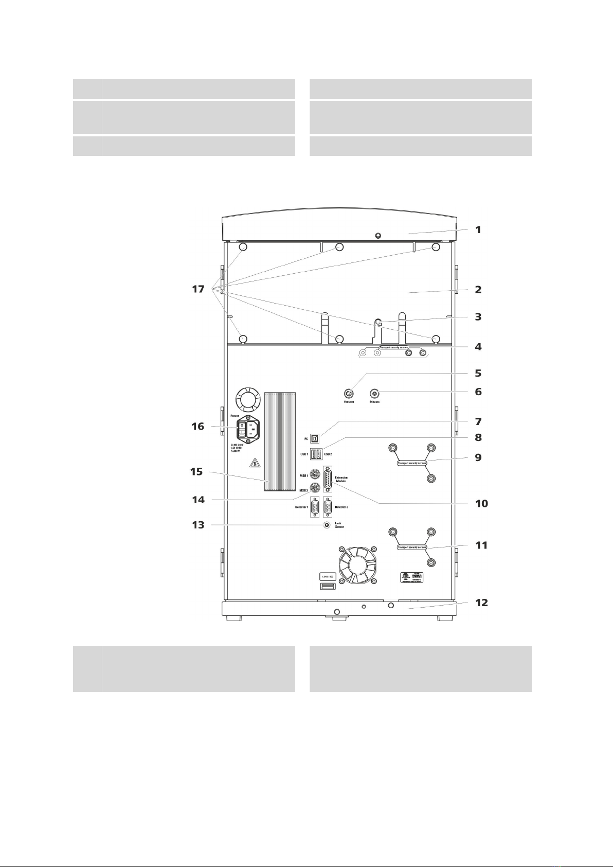
2.2 Rear
Figure 2 Rear
1Bottle holder
Offers space for the eluent bottle(s) and
additional accessories.
2Back panel
Removable. Enables access to the detector
chamber.

■■■■■■■■■■■■■■■■■■■■■■ 2 Overview of the instrument
940 Professional IC Vario ONE (2.940.1100) ■■■■■■■■ 9
3Drainage tubing connection
For connecting the drainage tubing, which
guides escaped liquids away from the detec-
tor chamber.
4Transport locking screws
For securing the vacuum pump(s) when
transporting the instrument. Up to two vac-
uum pumps can be installed in an instru-
ment. Only two transport locking screws are
used if just one vacuum pump is installed.
5Vacuum connection
For connecting an Extension Module that
has a degasser but not its own vacuum
pump. This connection has to be firmly
sealed with a stopper when not in use.
6Exhaust opening
Labeled Exhaust. For extracting the air from
the vacuum chamber.
7PC connection socket
For connecting the instrument to the com-
puter with the USB cable (6.2151.020).
8USB connection sockets
Labeled USB 1 and USB 2. For connecting
USB devices.
9Transport locking screws
For securing the high-pressure pump (in the
middle plug-in) when transporting the
instrument.
10 Extension Module connection socket
Labeled Extension Module. For connecting
the cable (6.2156.060) used for connecting
the instrument to the Extension Module.
11 Transport locking screws
For securing the high-pressure pump (in the
bottom plug-in) when transporting the
instrument. These screws are only installed if
a plug-in with a high-pressure pump is used
in the bottom slot.
12 Base tray
With leak sensor and leak sensor cable.
13 Leak sensor connection socket
Labeled Leak Sensor. For connecting the
leak sensor connection cable coiled up in
the base tray.
14 MSB connection sockets
Labeled MSB 1 and MSB 2. For connecting
MSB devices.
15 Cooler
For cooling the power supply unit. May
become hot!
16 Power socket
Power socket for connecting the power
cable and power switch for switching the
instrument on and off.
17 Knurled screws
For fastening the removable back panel.

2.3 Feed-throughs for capillaries and cables ■■■■■■■■■■■■■■■■■■■■■■
10 ■■■■■■■■ 940 Professional IC Vario ONE (2.940.1100)
2.3 Feed-throughs for capillaries and cables
Multiple openings are available for leading capillaries into the instrument
and for leading capillaries and cables out of the instrument:
■Openings on the door (see Figure 3, page 10)
■Openings on the back panel
■Ducts between the instrument and the base tray as well as between
the instrument and the bottle holder (see Figure 5, page 12)
Openings on the door
Figure 3 Feed-throughs on the door
1Luer connector
For connecting a capillary from inside and
for inserting a syringe (6.2816.020) from
outside. For manual sample injection.
2Opening for capillaries
For up to 3 capillaries.
An opening for up to 3 capillaries is located on the door of the instru-
ment.
The two Luer connections above are not actually openings; the capillaries
are fastened to the Luer connection from within using PEEK pressure
screws. You can use a syringe to inject or draw out liquid from the out-
side.

■■■■■■■■■■■■■■■■■■■■■■ 2 Overview of the instrument
940 Professional IC Vario ONE (2.940.1100) ■■■■■■■■ 11
Openings on the back panel
Figure 4 Openings for capillaries and cables
1Openings for capillaries 2Openings for cables
The removable back panel is outfitted with openings through which capil-
laries and cables can be lead out of the detector chamber.
Ducts for capillaries
There are ducts for capillaries between the instrument and base tray as
well as between the instrument and the bottle holder. The capillaries can
be fed to the front of the instrument from both sides of the instrument
and from the front of the instrument to the back of the instrument.

2.3 Feed-throughs for capillaries and cables ■■■■■■■■■■■■■■■■■■■■■■
12 ■■■■■■■■ 940 Professional IC Vario ONE (2.940.1100)
Figure 5 Ducts for capillaries
Other manuals for 940 Professional IC Vario ONE/ChS/LPG
3
Table of contents
Other Metrohm Medical Equipment manuals


