Metrohm Dialysis 6.5330.100 User manual

IC equipment
Dialysis 6.5330.100 | Dialysis Low Volume 6.5330.200
Manual
8.110.8028EN / 2018-09-07


Metrohm AG
CH-9100 Herisau
Switzerland
Phone +41 71 353 85 85
Fax +41 71 353 89 01
www.metrohm.com
IC equipment
Dialysis 6.5330.100 | Dialysis Low
Volume 6.5330.200
Manual
8.110.8028EN / 2018-09-07 ksah

Technical Communication
Metrohm AG
CH-9100 Herisau
This documentation is protected by copyright. All rights reserved.
This documentation has been prepared with great care. However, errors
can never be entirely ruled out. Please send comments regarding possible
errors to the address above.

■■■■■■■■■■■■■■■■■■■■■■ Table of contents
IC equipment Dialysis 6.5330.100 ■■■■■■■■ III
Table of contents
1 Introduction 1
1.1 Description of IC equipment: Dialysis | Dialysis Low Vol-
ume ........................................................................................ 1
1.2 Product versions .................................................................. 1
1.3 About the documentation ................................................... 2
1.4 Symbols and conventions .................................................... 2
2 Overview 4
2.1 Parts of the IC equipment: Dialysis | Dialysis Low Vol-
ume ........................................................................................ 4
2.2 Parts of the dialysis cell ........................................................ 5
2.3 Dialysis cell connectors ........................................................ 6
2.4 Mode of operation for dialysis ............................................ 7
3 Installation 8
3.1 Preparing the dialysis cell .................................................... 8
3.2 Connecting the dialysis cell ............................................... 12
3.3 Inserting the dialysis cell .................................................... 16
3.4 Conditioning the dialysis system ....................................... 18
4 Operation and maintenance 19
4.1 Operation ............................................................................ 19
4.1.1 Optimizing the dialysis ........................................................... 19
4.1.2 Recommended procedure for the dialysis ............................... 21
4.2 Maintenance ....................................................................... 23
5 Technical specifications 25
5.1 Dialysis cell (6.2729.100) ................................................... 25
5.2 Low Volume dialysis cell (6.2729.200) ............................. 25
5.3 Dialysis membrane (6.2714.010) ....................................... 25
5.4 Dialysis membrane (6.2714.030) ....................................... 25
6 Accessories 26
Index 27

Table of figures ■■■■■■■■■■■■■■■■■■■■■■
IV ■■■■■■■■ IC equipment Dialysis 6.5330.100
Table of figures
Figure 1 IC equipment: Dialysis | Dialysis Low Volume – Parts .......................... 4
Figure 2 Dialysis cell – Parts ............................................................................. 5
Figure 3 Dialysis cell – Connectors ................................................................... 6
Figure 4 Stopped-flow dialysis ......................................................................... 7
Figure 5 Area / transfer time diagram ............................................................ 20

■■■■■■■■■■■■■■■■■■■■■■ 1 Introduction
IC equipment Dialysis 6.5330.100 ■■■■■■■■ 1
1 Introduction
1.1 Description of IC equipment: Dialysis | Dialysis Low
Volume
The IC equipment: Dialysis 6.5330.100 | Dialysis Low Volume 6.5330.200
contains all accessory parts required for Inline Dialysis of matrix-contami-
nated samples (e.g. emulsions, samples containing fat and protein, body
fluids or waste waters with high pollution loads) directly before injection.
The main component of the IC equipment is the high-performance dialysis
cell. The ions travel through the semipermeable membrane, diffusing out
of the flowing sample and into the stationary acceptor solution, where
they are preconcentrated. The ion-preconcentrated acceptor solution is
then subsequently injected directly into the IC system.
To operate the dialysis cell, you need an IC system with a peristaltic pump
and a cell holder as well as a Sample Processor with a peristaltic pump.
1.2 Product versions
The IC equipment: Dialysis | Dialysis Low Volume is available in the follow-
ing versions.
Table 1 Product versions
Art. no. Designation Version feature Volume dialysis
cell
6.5330.100 IC equipment: Dialysis Dialysis cell (6.2729.100) 240 µL
6.5330.200 IC equipment: Dialysis Low Vol-
ume
Low Volume dialysis cell
(6.2729.200)
60 µL
The Low Volume dialysis cell (6.2729.200) requires a lower sample volume
than the dialysis cell (6.2729.100). The lower sample volume means that
transfer time, dialysis time, and the total analysis time are shorter.

1.3 About the documentation ■■■■■■■■■■■■■■■■■■■■■■
2■■■■■■■■ IC equipment Dialysis 6.5330.100
1.3 About the documentation
This manual describes the correct assembly and maintenance of the IC
equipment, as well as the installation of the capillary connections to and
from the dialysis cell. In addition, it describes how the dialysis works and
provides information on applying and optimizing the dialysis.
The installation of the peristaltic pump is not described in this manual. This
description can be found in the respective manuals for the ion chromato-
graph or respectively the Sample Processor.
CAUTION
Please read through this documentation carefully before putting the IC
equipment: Dialysis | Dialysis Low Volume into operation. The documen-
tation contains information and warnings which the user must follow in
order to ensure safe operation of the IC equipment: Dialysis | Dialysis
Low Volume.
1.4 Symbols and conventions
The following symbols and formatting may appear in this documentation:
Cross-reference to figure legend
The first number refers to the figure number, the sec-
ond to the instrument part in the figure.
Instruction step
Carry out these steps in the sequence shown.
Method Dialog text, parameter in the software
File ▶ New Menu or menu item
[Next] Button or key
WARNING
This symbol draws attention to a possible life-threat-
ening hazard or risk of injury.
WARNING
This symbol draws attention to a possible hazard due
to electrical current.

■■■■■■■■■■■■■■■■■■■■■■ 1 Introduction
IC equipment Dialysis 6.5330.100 ■■■■■■■■ 3
WARNING
This symbol draws attention to a possible hazard due
to heat or hot instrument parts.
WARNING
This symbol draws attention to a possible biological
hazard.
CAUTION
This symbol draws attention to possible damage to
instruments or instrument parts.
NOTE
This symbol highlights additional information and
tips.

2.1 Parts of the IC equipment: Dialysis | Dialysis Low Volume ■■■■■■■■■■■■■■■■■■■■■■
4■■■■■■■■ IC equipment Dialysis 6.5330.100
2 Overview
2.1 Parts of the IC equipment: Dialysis | Dialysis Low
Volume
Figure 1 IC equipment: Dialysis | Dialysis Low Volume – Parts
*Parts of IC equipment: Dialysis ** Parts of IC equipment: Dialysis Low
Volume

■■■■■■■■■■■■■■■■■■■■■■ 2 Overview
IC equipment Dialysis 6.5330.100 ■■■■■■■■ 5
2.2 Parts of the dialysis cell
Figure 2 Dialysis cell – Parts
1Stopper 2Donor chamber
3Sealing ring 4Acceptor chamber
5Washers 6Screws
For joining the acceptor and the donor
chamber.

2.3 Dialysis cell connectors ■■■■■■■■■■■■■■■■■■■■■■
6■■■■■■■■ IC equipment Dialysis 6.5330.100
2.3 Dialysis cell connectors
Figure 3 Dialysis cell – Connectors
1Donor chamber 2Acceptor chamber
3Outlet – Sample 4Inlet – Sample
5Inlet – Acceptor solution 6Outlet – Acceptor solution
NOTICE
The product number (6.2729.200) is only engraved in the Low Volume
dialysis cell.

■■■■■■■■■■■■■■■■■■■■■■ 2 Overview
IC equipment Dialysis 6.5330.100 ■■■■■■■■ 7
2.4 Mode of operation for dialysis
Figure 4 Stopped-flow dialysis
Sample is delivered continuously on the sample side of the dialysis cell.
After a rinsing phase, the acceptor flow is stopped. Because of the con-
centration gradient, the ions pass through the membrane. The acceptor
flow remains stationary until a concentration equilibrium is achieved
between the two cell halves. The concentration in the acceptor solution
thus matches the concentration of the original sample. Afterwards, the
acceptor solution is injected directly into the ion chromatograph.

3.1 Preparing the dialysis cell ■■■■■■■■■■■■■■■■■■■■■■
8■■■■■■■■ IC equipment Dialysis 6.5330.100
3 Installation
This chapter describes the assembly and connection of the dialysis cell and
the conditioning of the dialysis system.
Depending on the ion chromatograph, the dialysis cell may be placed at
different locations. Please observe the following recommendations:
■If you are working with an ion chromatograph that has a peristaltic
pump and a cell holder, then place the dialysis cell in the cell holder.
■If you are working with an ion chromatograph that has a peristaltic
pump but no cell holder, then place the dialysis cell holder
(6.2057.130) in the detector chamber of your ion chromatograph.
3.1 Preparing the dialysis cell
Required tools ■Dialysis cell
– Dialysis cell (6.2729.100)*
– Low Volume dialysis cell (6.2729.200)**
■Dialysis membrane (6.2714.010)
■Hex key (6.2621.070)
■Tweezers (6.2831.010)
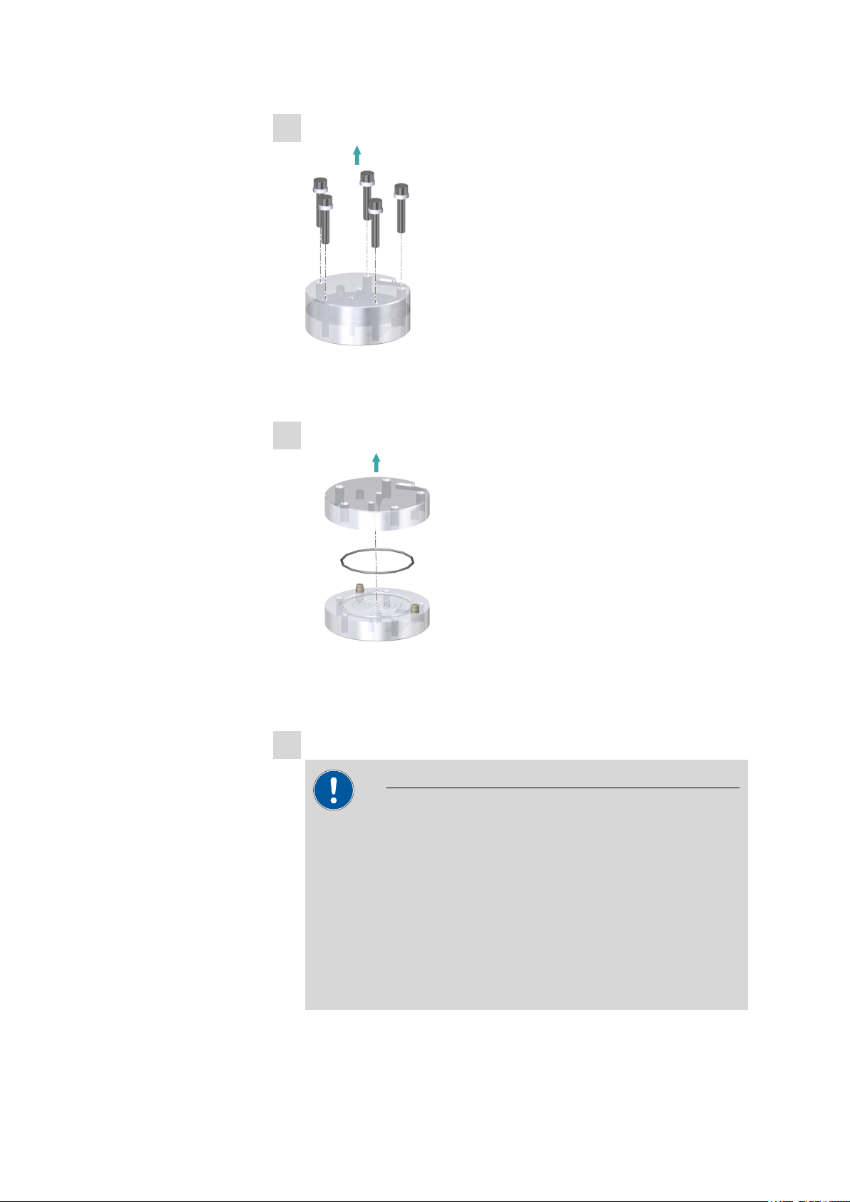
1Removing the stoppers
■Remove the four green stoppers.
■Turn the dialysis cell around and place it on a table.
The screws face upwards.
■■■■■■■■■■■■■■■■■■■■■■ 3 Installation
IC equipment Dialysis 6.5330.100 ■■■■■■■■ 9
2Removing the screws
■Loosen the screws with the hex key.
■Remove the screws with the washers and put them aside.
3Disassembling the dialysis cell
■Remove the upper part of the dialysis cell.
■Remove the sealing ring.
4Cleaning the dialysis cell
CAUTION
Damage to the dialysis cell
Organic solvents (e.g. acetone) corrode and damage the dialysis
cell material (PMMA).
■Use only ultrapure water or a water-ethanol mixture (70:30) for
cleaning the dialysis cell.
■For samples that contain organic components (e.g. solvents),
use the PEEK dialysis cell (6.2729.120). This cell has an excellent
chemical resistance to organic chemicals.

3.1 Preparing the dialysis cell ■■■■■■■■■■■■■■■■■■■■■■
10 ■■■■■■■■ IC equipment Dialysis 6.5330.100
■Thoroughly rinse off the sealing ring (2-3), the donor chamber
(2-2) and the acceptor chamber (2-4) of the dialysis cell with
ultrapure water.
■Dry all parts with a lint-free cloth.
5Wetting the dialysis membrane
NOTICE
In the package containing the dialysis membranes, you will find
sheets of different thicknesses and colors:
■The firm white cardboard is a cover protecting the filtration
membranes. Do not place it in the dialysis cell.
■The thin light-blue sheets are separation sheets placed between
two filtration membranes. Do not place them in the dialysis cell.
■The thin white sheets are the dialysis membranes. Use only
these for dialysis.
■Using the tweezers, take a new dialysis membrane out of the
package.
■Place the dialysis membrane in a petri dish filled with ultrapure
water and allow to hydrate for approx. two minutes.
6Inserting the dialysis membrane
NOTICE
Make sure that the water-soaked dialysis membrane does not dry
out before it is inserted, as it can otherwise no longer be used.

■■■■■■■■■■■■■■■■■■■■■■ 3 Installation
IC equipment Dialysis 6.5330.100 ■■■■■■■■ 11
■Place the sealing ring back in the recess.
■Using the tweezers, place the wet dialysis membrane centrally
inside the sealing ring onto the cell.
7Assembling the dialysis cell
■Place the upper part of the dialysis cell on the lower part in such a
way that the two guide bolts fit exactly into the two bore holes.
8Screwing the dialysis cell together
■Screw the five screws with the washers in the dialysis cell by hand
first.
■Then firmly tighten them with the hex key in crosswise sequence.
3.2 Connecting the dialysis cell ■■■■■■■■■■■■■■■■■■■■■■
12 ■■■■■■■■ IC equipment Dialysis 6.5330.100
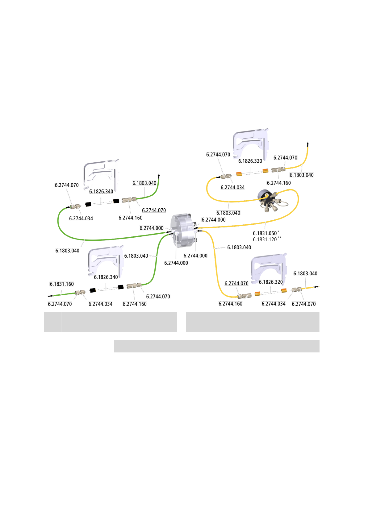
3.2 Connecting the dialysis cell
This chapter describes how to establish the capillary connections of the
dialysis system. It does not, however, describe the tubing configuration for
the peristaltic pump. Please refer to the chapter "Installing the peristaltic
pump" in the manual for the Sample Processor or the ion chromatograph
for this information.
*Parts of IC equipment: Dialysis ** Parts of IC equipment: Dialysis Low
Volume
Connections for acceptor solution
Required accessories ■Dialysis cell
– Dialysis cell (6.2729.100)*
– Low Volume dialysis cell (6.2729.200)**
■PTFE capillary, 0.5 mm ID / 1 m (6.1803.040)
■Pump tubing LFL (orange/yellow), 3 stoppers (6.1826.320)
■Pump tubing LFL (black/black), 3 stoppers (6.1826.340)
■PEEK capillary
– 0.5 mm ID / 40 cm (6.1831.050)*
– 0.25 mm ID / 45 cm (6.1831.120)**

■■■■■■■■■■■■■■■■■■■■■■ 3 Installation
IC equipment Dialysis 6.5330.100 ■■■■■■■■ 13
■PEEK capillary, 0.5 mm ID / 70 cm (6.1831.160)
■Pressure screw PVDF (6.2744.000)
■Coupling olive/UNF 10/32 (6.2744.030)
■Pressure screw, short (6.2744.070)
■Pump tubing connection with locking nut (6.2744.160)
We recommend using the peristaltic pump in the ion chromatograph for
conveying the acceptor solution.
The acceptor solution is pumped with two pump tubings with yellow/
orange stoppers (6.1826.320). Additional information on the tubing con-
figuration of the peristaltic pump can be found in the chapter "Installing
the peristaltic pump" in the manual for your ion chromatograph.
1Preparing two pump tubings for the sample
Use the two pump tubings with black stoppers (6.1826.340) for con-
veying the sample. Proceed as follows for each tubing:
■Attach the coupling olive/UNF 10/32 (6.2744.034) to the inlet.
■Attach the pump tubing connection with locking nut
(6.2744.160) to the outlet (see chapter "Installing the peristaltic
pump" in the manual for the ion chromatograph or in the man-
ual for the Sample Processor).
2Preparing two pump tubings for the acceptor solution
Use the two pump tubings with orange/yellow stoppers (6.1826.320)
for conveying the acceptor solution. Proceed as follows for each tub-
ing:
■Attach the coupling olive/UNF 10/32 (6.2744.034) to the inlet.
■Attach the pump tubing connection with locking nut
(6.2744.160) to the outlet (see chapter "Installing the peristaltic
pump" in the manual for the ion chromatograph or in the man-
ual for the Sample Processor).

3.2 Connecting the dialysis cell ■■■■■■■■■■■■■■■■■■■■■■
14 ■■■■■■■■ IC equipment Dialysis 6.5330.100
3Connecting the sample inlet
■Tighten the PEEK capillary, 0.5 mm ID / 70 cm (6.1831.160), to
the inlet of the pump tubing with black stoppers (6.1826.340)
using a pressure screw (6.2744.070).
Connect the other end of the PEEK capillary to the needle of the
Sample Processor (see manual for the Sample Processor).
■Tighten a PTFE capillary, 0.5 mm ID / 1 m (6.1803.040), to the
outlet of the pump tubing with black stoppers (6.1826.340) using
a pressure screw (6.2744.070).
Tighten the other end of the PTFE capillary to the sample inlet of
the dialysis cell (3-4) using a pressure screw (6.2744.000).
4Connecting the sample outlet
■Tighten a PTFE capillary 0.5 mm ID / 1 m (6.1803.040), to the
sample outlet of the dialysis cell (3-3) using a pressure screw
(6.2744.000).
Tighten the other end of the PTFE capillary to the inlet of the sec-
ond pump tubing with black stoppers (6.1826.340) using a pres-
sure screw (6.2744.070).
This manual suits for next models
1
Table of contents
Other Metrohm Medical Equipment manuals


Popular Medical Equipment manuals by other brands


AbleNet
AbleNet iTalk4 Series Getting started

InfuSystem
InfuSystem Cardinal Health CATALYST Patient Quick Reference Guide

Trumpf
Trumpf HELION S Service manual

Haag-Streit
Haag-Streit BP 900 Instructions for use

Getinge
Getinge ARJOHUNTLEIGH Maxi Air Transfer Instructions for use

Boston Scientific
Boston Scientific VERCISE DBS Handbook