Erbe EIP 2 User manual

2018-0780116-261
SERVICE MANUAL
EIP 2
V 1.0.x
V 1.1.x
ELECTROSURGERY


SERVICE MANUAL
EIP 2

Registered trademarks of Erbe Elektromedizin GmbH: AUTO CUT®, AXUS®, BICISION®, BiClamp®, classicCOAG®, classic-
CUT®, CLEVERCAP®, DeCo®, dryCUT®, endoCUT®, endoCOAG®, ERBE®, erbe power your performance.®, ERBECRYO®,
ERBEFLO®, ERBEFLO AeroRinse®, ERBEJET®, ERBELift®, ERBOKRYO®, FIAPC®, forcedCOAG®, Hybrid knife®,
HybridKnife®, ICC 200®, ICC 80®, KYRON®, NESSY®, NESSY Ω®, PLURA®, preciseAPC®, Preflow®, pulsedAPC®,
ReMode®, REMODE®, softCOAG®, sprayCOAG®, swiftCOAG®, The Color Blue®, thermoSEAL®, twinCOAG®, VIO®.
Service Manual Art. No. 80116-261
All rights to this manual, in particular rights of duplication, dissemination and translation, are reserved. No part of this man-
ual may be reproduced in any form (by photocopying, microfilming or other methods) or processed, duplicated or dissem-
inated by the use of electronic systems without the written consent of Erbe Elektromedizin GmbH.
The information contained in this manual may be amended or supplemented without prior notice and represents no obli-
gation on the part of Erbe Elektromedizin GmbH.
Printed by Erbe Elektromedizin
Printed in Germany
Copyright © Erbe Elektromedizin GmbH, Tübingen 2018

5 / 56
Table of Contents
80116-261
2018-07
Table of Contents
1Safety information . . . . . . . . . . . . . . . . . . . . . . . . . . . . . . . . . . . . . . . 7
Classification of the safety information. . . . . . . . . . . . . . . . . . . . . . . . . . . . . . . . . 7
Knowledge of the User Manual . . . . . . . . . . . . . . . . . . . . . . . . . . . . . . . . . . . . . . . 7
Protection from the risk of electric shock . . . . . . . . . . . . . . . . . . . . . . . . . . . . . . . 7
Electrostatically sensitive components . . . . . . . . . . . . . . . . . . . . . . . . . . . . . . . . . 8
Liability and warranty . . . . . . . . . . . . . . . . . . . . . . . . . . . . . . . . . . . . . . . . . . . . . . . 8
2Modifications. . . . . . . . . . . . . . . . . . . . . . . . . . . . . . . . . . . . . . . . . . . . 9
3Unit description. . . . . . . . . . . . . . . . . . . . . . . . . . . . . . . . . . . . . . . . . 11
Unit variants . . . . . . . . . . . . . . . . . . . . . . . . . . . . . . . . . . . . . . . . . . . . . . . . . . . . . 11
Factory setting . . . . . . . . . . . . . . . . . . . . . . . . . . . . . . . . . . . . . . . . . . . . . . . . . . . 11
Controls . . . . . . . . . . . . . . . . . . . . . . . . . . . . . . . . . . . . . . . . . . . . . . . . . . . . . . . . . 12
Controls at the front. . . . . . . . . . . . . . . . . . . . . . . . . . . . . . . . . . . . . . . . . . . . . 12
Symbols. . . . . . . . . . . . . . . . . . . . . . . . . . . . . . . . . . . . . . . . . . . . . . . . . . . . . . . 13
Controls at the rear . . . . . . . . . . . . . . . . . . . . . . . . . . . . . . . . . . . . . . . . . . . . . 13
Description of function . . . . . . . . . . . . . . . . . . . . . . . . . . . . . . . . . . . . . . . . . . . . . 14
4Technical Data . . . . . . . . . . . . . . . . . . . . . . . . . . . . . . . . . . . . . . . . . . 15
5Installation. . . . . . . . . . . . . . . . . . . . . . . . . . . . . . . . . . . . . . . . . . . . . 17
Installation possibilities . . . . . . . . . . . . . . . . . . . . . . . . . . . . . . . . . . . . . . . . . . . . 17
6Circuit Descriptions . . . . . . . . . . . . . . . . . . . . . . . . . . . . . . . . . . . . . . 19
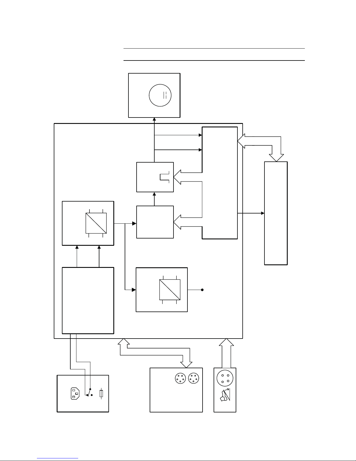
Block diagram EIP 2 (120 V / 230 V) . . . . . . . . . . . . . . . . . . . . . . . . . . . . . . . . . 20
Block diagram EIP 2 (100 V). . . . . . . . . . . . . . . . . . . . . . . . . . . . . . . . . . . . . . . . . 21
Beschreibung der einzelnen Baugruppen . . . . . . . . . . . . . . . . . . . . . . . . . . . . . . 22
Line input . . . . . . . . . . . . . . . . . . . . . . . . . . . . . . . . . . . . . . . . . . . . . . . . . . . . . 22
Transformer . . . . . . . . . . . . . . . . . . . . . . . . . . . . . . . . . . . . . . . . . . . . . . . . . . . 22
Bridge-connected rectifier. . . . . . . . . . . . . . . . . . . . . . . . . . . . . . . . . . . . . . . . 22
Switching controller . . . . . . . . . . . . . . . . . . . . . . . . . . . . . . . . . . . . . . . . . . . . . 22
Monitoring the motor control . . . . . . . . . . . . . . . . . . . . . . . . . . . . . . . . . . . . . 22
Motor control . . . . . . . . . . . . . . . . . . . . . . . . . . . . . . . . . . . . . . . . . . . . . . . . . . 22
Microcontroller . . . . . . . . . . . . . . . . . . . . . . . . . . . . . . . . . . . . . . . . . . . . . . . . . 23
CAN module (optional). . . . . . . . . . . . . . . . . . . . . . . . . . . . . . . . . . . . . . . . . . . 23
Footswitch . . . . . . . . . . . . . . . . . . . . . . . . . . . . . . . . . . . . . . . . . . . . . . . . . . . . 23
Control panel . . . . . . . . . . . . . . . . . . . . . . . . . . . . . . . . . . . . . . . . . . . . . . . . . . 23
Motor. . . . . . . . . . . . . . . . . . . . . . . . . . . . . . . . . . . . . . . . . . . . . . . . . . . . . . . . . 23

Table of Contents
6 / 56
80116-261
2018-07
7Service programs . . . . . . . . . . . . . . . . . . . . . . . . . . . . . . . . . . . . . . . . 25
Calling up service program mode. . . . . . . . . . . . . . . . . . . . . . . . . . . . . . . . . . . . . 25
Navigating between service programs. . . . . . . . . . . . . . . . . . . . . . . . . . . . . . . . . 25
Leaving the service program mode . . . . . . . . . . . . . . . . . . . . . . . . . . . . . . . . . . . 25
Description of service programs. . . . . . . . . . . . . . . . . . . . . . . . . . . . . . . . . . . . . . 26
Service program S1 Flow test. . . . . . . . . . . . . . . . . . . . . . . . . . . . . . . . . . . . . .26
Service program S2 LED Test . . . . . . . . . . . . . . . . . . . . . . . . . . . . . . . . . . . . . .27
Service program S3 Continuous running / Burn-In . . . . . . . . . . . . . . . . . . . .28
Service program S4 Version output . . . . . . . . . . . . . . . . . . . . . . . . . . . . . . . . .29
Service program S5 Automatic pressure control. . . . . . . . . . . . . . . . . . . . . . .30
8Remedying malfunctions. . . . . . . . . . . . . . . . . . . . . . . . . . . . . . . . . . 31
9Maintenance and servicing . . . . . . . . . . . . . . . . . . . . . . . . . . . . . . . . 33
Technical safety check, national regulations, trained persons . . . . . . . . . . . . . . 33
Test intervals . . . . . . . . . . . . . . . . . . . . . . . . . . . . . . . . . . . . . . . . . . . . . . . . . . . . . 33
Technical safety check . . . . . . . . . . . . . . . . . . . . . . . . . . . . . . . . . . . . . . . . . . . . . . 34
Important information. . . . . . . . . . . . . . . . . . . . . . . . . . . . . . . . . . . . . . . . . . . .34
User manual and visual inspections. . . . . . . . . . . . . . . . . . . . . . . . . . . . . . . . .35
Tests to be conducted in accordance with the national specifications
and regulations . . . . . . . . . . . . . . . . . . . . . . . . . . . . . . . . . . . . . . . . . . . . . . . . .35
Performance tests . . . . . . . . . . . . . . . . . . . . . . . . . . . . . . . . . . . . . . . . . . . . . . .35
10 Replacing components . . . . . . . . . . . . . . . . . . . . . . . . . . . . . . . . . . . 37
Change pump head . . . . . . . . . . . . . . . . . . . . . . . . . . . . . . . . . . . . . . . . . . . . . . . . 37
Change gear motor . . . . . . . . . . . . . . . . . . . . . . . . . . . . . . . . . . . . . . . . . . . . . . . . 39
Change main board . . . . . . . . . . . . . . . . . . . . . . . . . . . . . . . . . . . . . . . . . . . . . . . . 44
11 Spare parts. . . . . . . . . . . . . . . . . . . . . . . . . . . . . . . . . . . . . . . . . . . . . 47
Abbreviations . . . . . . . . . . . . . . . . . . . . . . . . . . . . . . . . . . . . . . . . . . . . . . . . . . . . . 47
EIP 2 without ECB . . . . . . . . . . . . . . . . . . . . . . . . . . . . . . . . . . . . . . . . . . . . . . . . . 48
EIP 2 with ECB . . . . . . . . . . . . . . . . . . . . . . . . . . . . . . . . . . . . . . . . . . . . . . . . . . . 52

7 / 56
1 •Safety information
80116-261
2018-07
CHAPTER 1
Safety information
Classification of the safety information
Knowledge of the User Manual
The User Manual for this unit constitutes an integral part of this Service
Manual. For performing servicing activities it is assumed that the reader
has knowledge of the User Manual, especially procedures for installation,
putting into operation, and handling.
Protection from the risk of electric shock
WARNING! The WARNING! safety indication refers to a risk of personal injury.
CAUTION! The CAUTION! safety indication refers to a risk of damage to property.
ATTENTION! The ATTENTION! safety indication refers to a risk which can cause
equipment to become unserviceable.
IMPORTANT! The IMPORTANT! designation indicates application information and
other particularly important information.
WARNING! The supply voltage must match the voltage specified on the rating
plate. Connect the unit / the equipment cart to a properly installed
grounded outlet. Only use the Erbe power cord or an equivalent power
cord for this purpose. The power cord must bear the national test sym-
bol.
For safety reasons, multiple outlets and extension cords should not be
used. If their use is unavoidable, they also must be provided with proper
grounding.
WARNING! Unplug the power cord from the outlet before exchanging parts of the
unit or cleaning it.
WARNING! Do not plug a wet power cord into the unit or into an outlet.

1 •Safety information
8/ 56
80116-261
2018-07
Electrostatically sensitive components
Liability and warranty
WARNING! Do not touch any unprotected wires or conductive surfaces while the
unit is opened and under voltage.
WARNING! Blown line fuses may only be replaced by a competent technician. Only
replacement fuses of the rating specified on the unit's name plate may
be used. Before resuming operation the unit must be subjected to a
performance test by a competent technician.
CAUTION! This unit contains electrostatically sensitive components. Work at an
anti-static workplace while repairing the unit. Wear a grounding arm-
band while working with electrostatically sensitive components. Hold
the circuit boards by their non-conducting corners. Use an anti-static
container for transporting electrostatically sensitive components and
the circuit boards.
ATTENTION! Adjustments, tests, modifications, maintenance and repair work may
only be performed by Erbe or persons trained by Erbe. If the work is not
performed by trained persons, Erbe accepts no liability and warranty
rights become void.
It is recommended that the technical safety check also be performed by
Erbe or persons trained by Erbe.
ATTENTION! Only use original Erbe spare parts. The manufacturer accepts no liability
and the warranty rights becomes void if original spare parts are not
used.

9 / 56
2 •Modifications
80116-261
2018-07
CHAPTER 2
Modifications
From V 1.1.x
Hardware
No changes
Software
Component affected Description of the modification
Service programs New Service program:
S 5 Automatic pressure control

2 •Modifications
10 / 56
80116-261
2018-07

11 / 56
3 •Unit description
80116-261
2018-07
CHAPTER 3
Unit description
Unit variants
The EIP 2 (Erbe Irrigation Pump) is available in the following unit variants:
•230 V with ECB socket
1
•230 V without ECB socket
•120 V without ECB socket
•100 V with ECB socket
•100 V without ECB socket
Factory setting
The EIP 2 has the following settings when it is delivered by the manufac-
turer:
•Quick activation button I = 30%
2
•Quick activation button II = 50%
•Quick activation button III = 80%
•Automatic pressure control activated
for units up to software version 1.0.0
•Automatic pressure control deactivated
(for units from software version 1.1.0)
1. ECB = Erbe Communication Bus for connecting the EIP 2 to a VIO electrosurgical unit.
2. Flow in % relative to the maximum flow of 500 ml/min.
IMPORTANT! Once settings have been changed and saved they still apply even after
the unit has been restarted. A reset (= switching the unit back to the
factory setting) is not possible.

3 •Unit description
12 / 56
80116-261
2018-07
Controls
Controls at the front
Fig. 3-1
IMPORTANT! This chapter contains an overview of the controls of the unit(s). The rel-
evant User Manual for the unit(s), knowledge of which is assumed for
servicing work, provides detailed information about how to use the
unit(s).
1
2
3
4
56
7
8
9
1Power switch
2 Quick activation button I (30 % of capacity1/ approx. 150 ml/min)
3Quick activation button II (50 % of capacity / approx. 250 ml/min)
4Quick activation button III (80 % of capacity / approx. 400 ml/min)
5Flow display
6Up / Down buttons
7Activation button
8Pump head lid
9Direction arrow for irrigation liquid
1. Flow in % relative to the maximum flow of 500 ml/min.

13 / 56
3 •Unit description
80116-261
2018-07
Symbols
Read User Manual.
The unit meets the requirements of Type CF and is protected against the
effects of a defibrillator discharge.
Never place your fingers in the pump head.
Controls at the rear
Fig. 3-2
1
2
3
4
5
1Optional ECB socket (ECB = Erbe Communication Bus) for connecting
the EIP 2 to a VIO electrosurgical unit
2Footswitch socket
3Potential equalization
4 Power connection
5Power fuse

3 •Unit description
14 / 56
80116-261
2018-07
Description of function
Peristaltic pump principle The EIP 2 (Erbe Irrigation Pump) is a peristaltic pump. This operating prin-
ciple is based on pressing or squeezing a flexible pump hose at one or
more points and on movement of the squeezed point in the desired direc-
tion of liquid flow. For this reason peristaltic pumps are sometimes re-
ferred to as peristaltic squeeze pumps. Movement of the squeezed point is
accomplished with the aid of a pump rotor that has rollers around its pe-
rimeter. Flow is determined by rotor speed (speed of motion of the
squeezed point) and internal cross-section of the hose.
Advantages of peristaltic pumps With peristaltic pumps the medium and the pump do not come into contact
with one another. Therefore peristaltic pumps are particularly suited for
metering a very wide range of media. As opposed to other types of pump
like diaphragm pumps, with peristaltic pumps it is very easy to adapt the
material of the pump hose, or components coming into contact with the
medium, to the product being pumped. A pump hose is selected and used
that is chemically suited for the product being pumped ("milled hose").

15 / 56
4 •Technical Data
80116-261
2018-07
CHAPTER 4
Technical Data
Power supply for devices with 230 V
Nominal line voltage Line current Power fuse Nominal line frequency
230 V ± 10% 200 mA T 0.2 A 50 / 60 Hz
Power input in Standby Mode 5 W
Power input at max. irrigation flow 20 W
Potential equalization terminal Yes
Power supply for devices with 120 V
Nominal line voltage Line current Power fuse Nominal line frequency
120 V ± 10% 400 mA T 0.4 A 50 / 60 Hz
Power input in Standby Mode 3 W
Power input at max. irrigation flow 20 W
Potential equalization terminal Yes
Power supply for devices with 100 V
Nominal line voltage Line current Power fuse Nominal line frequency
100 V ± 10 % 315 mA T 0.315 A 50 / 60 Hz
Power input in Standby Mode 3 W
Power input at max. irrigation flow 20 W
Potential equalization terminal Yes
Operating mode
Continuous duty Yes

4 •Technical Data
16 / 56
80116-261
2018-07
Dimensions and weight
Width x height x depth 205 x 125 x 170 mm (without pump head)
Width x height x depth 205 x 125 x 210 mm (with pump head)
Weight 3 kg
Ambient conditions for transport and storage of unit
Tem perature -40 °C to + 70 °C
Relative humidity 10% – 95%
Ambient conditions for operation of unit
Tem perature +10 °C to + 40 °C
Relative humidity 15% – 80%, noncondensing
Acclimatizing
If the unit has been stored or transported at temperatures below +10 °C or above +40 °C, the unit will
require approx. 3 hours to acclimatize at room temperature.
Standards
Classification according to EC Directive 93/42/EEC II a
Protection class as per EN 60 601-1 I
Type as per EN 60 601-1 CF

17 / 56
5 •Installation
80116-261
2018-07
CHAPTER 5
Installation
Installation possibilities
For EIP 2 (Erbe Irrigation Pump) there are three installation possibilities:
•Installation on an Erbe VIO Cart.
•Installation on an Erbe Universal Cart.
•EIP 2 as a stand alone variant.
These installation possibilities are described in the User Manual for the
EIP 2 and the User Manuals for the above equipment carts.

5 •Installation
18 / 56
80116-261
2018-07

19 / 56
6 •Circuit Descriptions
80116-261
2018-07
CHAPTER 6
Circuit Descriptions

6 •Circuit Descriptions
20 / 56
80116-261
2018-07
Block diagram EIP 2 (120 V / 230 V)
Fig. 6-1
M
AC
DC
DC
DC
Line input
Transformer Bridge-
connected
Switching
Mainboard Microcontroller
Motor
Control panel
Monitoring
the
motor
control
Motor
control
(PWM)
CAN module
(optional)
120 V
230 V
ECB 1
ECB 2
2 x 9 V
1.33 A
24 V
24 V
5 V
ECB Erbe Communication Bus
U-Motor
U-Motor
I-Motor
5 V
rectifier
controller
Table of contents
Other Erbe Medical Equipment manuals

Erbe
Erbe VIO 200 D User manual

Erbe
Erbe 20183-070 Operating instructions

Erbe
Erbe ERBOTOM ICC 300 User manual

Erbe
Erbe VIO 3 User manual

Erbe
Erbe 20191-331 Operating instructions

Erbe
Erbe VIO 100 C User manual

Erbe
Erbe ESM 2 User manual

Erbe
Erbe 20321-040 User manual

Erbe
Erbe 20195-080 User manual

Erbe
Erbe 20134-004 Operating instructions