Metrohm 6.5330.110 User manual

IC equipment
IC equipment: Inline-Ultrafiltration (6.5330.110)
Manual
8.110.8037EN / 2014-02-20


Metrohm AG
CH-9100 Herisau
Switzerland
Phone +41 71 353 85 85
Fax +41 71 353 89 01
www.metrohm.com
IC equipment
IC equipment: Inline-Ultrafiltration
(6.5330.110)
Manual
8.110.8037EN / 2014-02-20 zst

Technical Communication
Metrohm AG
CH-9100 Herisau
This documentation is protected by copyright. All rights reserved.
This documentation has been prepared with great care. However, errors
can never be entirely ruled out. Please send comments regarding possible
errors to the address above.

■■■■■■■■■■■■■■■■■■■■■■ Table of contents
IC equipment: Inline-Ultrafiltration ■■■■■■■■ III
Table of contents
1 Introduction 1
1.1 Description of the IC equipment: Inline-Ultrafiltration ...... 1
1.2 About the documentation ................................................... 1
1.3 Symbols and conventions .................................................... 2
2 Overview 3
2.1 Parts of the IC equipment: Inline-Ultrafiltration ................ 3
2.2 Components of the ultrafiltration cell ................................ 3
2.3 Connectors of the ultrafiltration cell ................................... 4
2.4 Mode of operation for ultrafiltration .................................. 5
3 Installation 6
3.1 Preparing the ultrafiltration cell .......................................... 6
3.2 Connecting the ultrafiltration cell ..................................... 10
3.3 Inserting the ultrafiltration cell ......................................... 13
3.4 Deaerating the ultrafiltration cell ...................................... 15
4 Operation and maintenance 17
4.1 Operation ............................................................................ 17
4.1.1 Service life of the filtration membrane .................................... 17
4.1.2 Selecting the filtration membrane .......................................... 18
4.2 Maintenance ....................................................................... 19
5 Technical specifications 21
5.1 Ultrafiltration cell (6.2729.110) ......................................... 21
5.2 Filtration membrane (6.2714.020) .................................... 21
5.3 Dialysis membrane (6.2714.030) ....................................... 21
6 Accessories 22
Index 23

Table of figures ■■■■■■■■■■■■■■■■■■■■■■
IV ■■■■■■■■ IC equipment: Inline-Ultrafiltration
Table of figures
Figure 1 IC equipment: Inline-Ultrafiltration – Parts .......................................... 3
Figure 2 Ultrafiltration cell – Parts .................................................................... 3
Figure 3 Ultrafiltration cell – Connectors ......................................................... 4
Figure 4 Connecting the ultrafiltration cell ..................................................... 10

■■■■■■■■■■■■■■■■■■■■■■ 1 Introduction
IC equipment: Inline-Ultrafiltration ■■■■■■■■ 1
1 Introduction
1.1 Description of the IC equipment: Inline-Ultrafiltra-
tion
The IC equipment: Inline-Ultrafiltration (6.5330.110) contains all accesso-
ries required for Inline Ultrafiltration of difficult samples directly before
injection.
The main component of the IC equipment: Inline-Ultrafiltration is the high-
performance ultrafiltration cell. This cell is suitable for the filtration of sam-
ples that pose particular requirements with regard to filtration effective-
ness and sample throughput.
The two channels of a peristaltic pump are required for pumping the sam-
ple and the filtrate.
1.2 About the documentation
This manual describes the correct assembly and maintenance of the IC
equipment: Inline-Ultrafiltration, the installation of the capillary connec-
tions to and from the ultrafiltration cell and how to mount the holder on
both the Sample Processor and the IC instrument.
The installation of the peristaltic pump is not described in this manual. This
description can be found in the respective manuals for the ion chromato-
graph or the Sample Processor.
CAUTION
Please read through this documentation carefully before putting the IC
equipment: Inline-Ultrafiltration into operation. The documentation
contains information and warnings which the user must follow in order
to ensure safe operation of the IC equipment: Inline-Ultrafiltration.

1.3 Symbols and conventions ■■■■■■■■■■■■■■■■■■■■■■
2■■■■■■■■ IC equipment: Inline-Ultrafiltration
1.3 Symbols and conventions
The following symbols and formatting may appear in this documentation:
Cross-reference to figure legend
The first number refers to the figure number, the sec-
ond to the instrument part in the figure.
Instruction step
Carry out these steps in the sequence shown.
Method Dialog text, parameter in the software
File ▶ New Menu or menu item
[Next] Button or key
WARNING
This symbol draws attention to a possible life-threat-
ening hazard or risk of injury.
WARNING
This symbol draws attention to a possible hazard due
to electrical current.
WARNING
This symbol draws attention to a possible hazard due
to heat or hot instrument parts.
WARNING
This symbol draws attention to a possible biological
hazard.
CAUTION
This symbol draws attention to possible damage to
instruments or instrument parts.
NOTE
This symbol highlights additional information and
tips.

■■■■■■■■■■■■■■■■■■■■■■ 2 Overview
IC equipment: Inline-Ultrafiltration ■■■■■■■■ 3
2 Overview
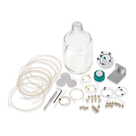
2.1 Parts of the IC equipment: Inline-Ultrafiltration
6.1803.080
6.2831.010
6.2057.030
6.2744.160
6.2621.0706.2744.030
6.2744.070
6.2744.000
6.2729.110
6.1826.320
6.1826.390
6.1803.050
6.2714.020
6.1831.060
6.1831.160
Figure 1 IC equipment: Inline-Ultrafiltration – Parts
2.2 Components of the ultrafiltration cell
Figure 2 Ultrafiltration cell – Parts
1Stoppers 2Upper chamber

2.3 Connectors of the ultrafiltration cell ■■■■■■■■■■■■■■■■■■■■■■
4■■■■■■■■ IC equipment: Inline-Ultrafiltration
3Sealing ring 4Lower chamber
5Washers 6Screws
For joining the upper and the lower part of
the cell.
2.3 Connectors of the ultrafiltration cell
Figure 3 Ultrafiltration cell – Connectors
1Upper chamber 2Lower chamber
3Filtrate outlet
Labeled OUT.
4Sample inlet
Labeled IN.
5Sample outlet
Labeled OUT.

■■■■■■■■■■■■■■■■■■■■■■ 2 Overview
IC equipment: Inline-Ultrafiltration ■■■■■■■■ 5
2.4 Mode of operation for ultrafiltration
The peristaltic pump delivers a continuous flow of sample solution at a
high rate through the lower chamber of the ultrafiltration cell. The sample
flows along the filtration membrane and then to the waste container.
At the same time, the peristaltic pump's second channel generates a vac-
uum in the upper chamber of the ultrafiltration cell, thus pulling the sam-
ple solution through the filtration membrane. The filtrate reaches the sam-
ple loop and is then injected.
Less than 20% of the original sample solution volume is analyzed as fil-
trate. The remainder flows directly into the waste container.

3.1 Preparing the ultrafiltration cell ■■■■■■■■■■■■■■■■■■■■■■
6■■■■■■■■ IC equipment: Inline-Ultrafiltration
3 Installation
This chapter describes how to assemble the ultrafiltration cell, how to fas-
ten the ultrafiltration cell to the Sample Processor or in the ion chromato-
graph and how to connect the ultrafiltration cell to the peristaltic pump
and the injection valve.
Depending on the device combination, the ultrafiltration cell may be
placed at different locations. Please observe the following recommenda-
tions:
Devices Peristaltic pump Ultrafiltration cell
Sample Processor with
peristaltic pump and ion
chromatograph
on the Sample Processor on the Sample Processor
Only ion chromatograph,
type Prep 1
on the ion chromatograph on the ion chromatograph
Only ion chromatograph
with peristaltic pump
on the ion chromatograph in the detector chamber of
the ion chromatograph
with cell holder
(6.2057.120)
3.1 Preparing the ultrafiltration cell
Inserting the filtration membrane
Required accessories ■Ultrafiltration cell (6.2729.110)
■Filtration membrane (6.2714.020)
■5 mm hex key for IC Sample Processors (6.2621.070)
■Plastic tweezers (6.2831.010)
1Removing the stoppers

■■■■■■■■■■■■■■■■■■■■■■ 3 Installation
IC equipment: Inline-Ultrafiltration ■■■■■■■■ 7
■Remove the 3 green stoppers.
■Turn the ultrafiltration cell around and place it on a table. The
screws face upwards.
2Removing the screws
■Loosen the screws with the hex key.
■Remove the screws with the washers and put them aside.
3Disassembling the ultrafiltration cell
■Remove the upper chamber of the ultrafiltration cell.
■Remove the sealing ring.
4Cleaning the ultrafiltration cell
CAUTION
Damage to the ultrafiltration cell
Organic solvents (e.g. acetone) corrode and damage the ultrafiltra-
tion cell material (PMMA).
Use only ultrapure water or a water-ethanol mixture (70:30) for
cleaning the ultrafiltration cell.

3.1 Preparing the ultrafiltration cell ■■■■■■■■■■■■■■■■■■■■■■
8■■■■■■■■ IC equipment: Inline-Ultrafiltration
■Thoroughly rinse off the sealing ring, the upper chamber and the
lower chamber of the ultrafiltration cell with ultrapure water.
■Dry all parts with a lint-free cloth.
5Wetting the filtration membrane
NOTICE
In the package containing the filtration membranes, you will find
sheets of different thicknesses and colors:
■The firm white cardboard is a cover protecting the filtration
membranes. Do not insert the cover into the ultrafiltration cell.
■The thin light-blue sheets are separation sheets placed between
2 filtration membranes. Do not insert the separation sheets into
the ultrafiltration cell.
■The thin white sheets are the filtration membranes. Only insert
the filtration membranes into the ultrafiltration cell.
■Using the tweezers, take a new filtration membrane out of the
package.
■Place the filtration membrane in a petri dish filled with ultrapure
water and allow to hydrate for approx. 2 minutes.
6Inserting the filtration membrane
NOTICE
The water-soaked filtration membrane must not dry out before it is
inserted. Otherwise it can no longer be used.

■■■■■■■■■■■■■■■■■■■■■■ 3 Installation
IC equipment: Inline-Ultrafiltration ■■■■■■■■ 9
■Place the sealing ring back in the recess.
■Using the tweezers, place the wet filtration membrane centrally
inside the sealing ring onto the cell.
7Assembling the ultrafiltration cell
■Place the upper chamber of the ultrafiltration cell on the lower
chamber in such a way that the 2 guide bolts exactly fit into the 2
bore holes.
8Screwing the ultrafiltration cell together
■Screw the 5 screws with the washers in the ultrafiltration cell by
hand first.
■Then firmly tighten them with the hex key in crosswise sequence.

3.2 Connecting the ultrafiltration cell ■■■■■■■■■■■■■■■■■■■■■■
10 ■■■■■■■■ IC equipment: Inline-Ultrafiltration
3.2 Connecting the ultrafiltration cell
This chapter describes how to establish the capillary connections of the fil-
tration system (regardless of whether the filtration cell is installed on the
Sample Processor or in the ion chromatograph). It does not, however,
describe the tubing configuration for the peristaltic pump. Please refer to
the chapter "Installing the peristaltic pump" in the manual for the Sam-
ple Processor or the ion chromatograph for this information.
The following figure shows a schematic overview of all capillary connec-
tions of the filtration system.
6.1831.160
6.2744.030
6.2744.070 6.1826.390
6.2744.070
6.2744.160
6.1803.050 6.2744.030
6.2744.070 6.1826.320
6.2744.070
6.2744.160
6.1831.060
6.1803.050
6.1803.080
6.2744.000
6.2744.000
6.2744.000
Figure 4 Connecting the ultrafiltration cell
NOTICE
■In order to keep dead volume to a minimum, make sure that the
capillaries are as short as possible.
■The capillaries that are used for transferring the filtrate are thinner
than the capillaries used for transferring the sample.
■To prevent the capillaries leading into the ion chromatograph from
being pinched, always guide them through the capillary feed-
throughs provided for this purpose (see the manual for the ion chro-
matograph).
Connecting the ultrafiltration cell
Required accessories ■Ultrafiltration cell (6.2729.110)
■PTFE capillary, 0.5 mm ID / 20 cm (6.1803.050)
■PTFE capillary, 0.97 mm ID / 1 m (6.1803.080)
■Pump tubing LFL (orange/yellow), 3 stoppers (6.1826.320)
■Pump tubing LFL (yellow/yellow), 3 stoppers (6.1826.390)
■PEEK capillary, 0.5 mm ID / 1 m (6.1831.060)
■PEEK capillary, 0.5 mm ID / 70 cm (6.1831.160)
■Pressure screw PVDF (6.2744.000)

■■■■■■■■■■■■■■■■■■■■■■ 3 Installation
IC equipment: Inline-Ultrafiltration ■■■■■■■■ 11
■Coupling olive/UNF 10/32 (6.2744.030)
■Pressure screw, short (6.2744.070)
■Pump tubing connection with locking nut (6.2744.160)
1Preparing the pump tubing for the sample
Use the pump tubing with yellow stoppers (6.1826.390) for convey-
ing the sample.
■Attach the coupling olive/UNF 10/32 (6.2744.030) to the inlet.
■Attach the pump tubing connection with locking nut
(6.2744.160) to the outlet (see chapter "Installing the peristaltic
pump" in the manual for the ion chromatograph or in the man-
ual for the Sample Processor).
2Preparing the pump tubing for the filtrate
Use the pump tubing with orange/yellow stoppers (6.1826.320) for
conveying the filtrate.
■Attach the coupling olive/UNF 10/32 (6.2744.030) to the inlet.
■Attach the pump tubing connection with locking nut
(6.2744.160) to the outlet (see chapter "Installing the peristaltic
pump" in the manual for the ion chromatograph or in the man-
ual for the Sample Processor).
3Connecting the capillaries to the pump tubing for the sample
6.1831.160
6.2744.070
6.2744.070 6.1803.050
6.2744.030
6.2744.160
6.1826.390
■Tighten the PEEK capillary (6.1831.160) to the inlet of the pump
tubing with yellow stoppers (6.1826.390) using a pressure screw
(6.2744.070).
■Tighten the PTFE capillary (6.1803.050) to the outlet of the pump
tubing with yellow stoppers (6.1826.390) using a pressure screw
(6.2744.070).

3.2 Connecting the ultrafiltration cell ■■■■■■■■■■■■■■■■■■■■■■
12 ■■■■■■■■ IC equipment: Inline-Ultrafiltration
4Connecting the capillaries to the pump tubing for the filtrate
■Tighten the PTFE capillary (6.1803.050) to the inlet of the pump
tubing with orange/yellow stoppers (6.1826.320) using a pressure
screw (6.2744.070).
■Tighten the PEEK capillary (6.1831.060) to the outlet of the pump
tubing with orange/yellow stoppers (6.1826.320) using a pressure
screw (6.2744.070).
5Connecting capillaries to the ultrafiltration cell
CAUTION
Use only PVDF pressure screws (6.2744.000) to tighten capillaries
to the ultrafiltration cell.
PEEK pressure screws are too hard and could damage the ultrafil-
tration cell material.
6.2744.000
6.1803.050
6.1803.050
6.1803.080
6.2744.000
■Tighten the PTFE capillary (6.1803.060) to the inlet labeled IN of
the ultrafiltration cell's lower chamber using a PVDF pressure
screw (6.2744.000).
■Tighten the PTFE capillary (6.1803.080) to the outlet labeled OUT
of the ultrafiltration cell's lower chamber using a PVDF pressure
screw (6.2744.000).

■■■■■■■■■■■■■■■■■■■■■■ 3 Installation
IC equipment: Inline-Ultrafiltration ■■■■■■■■ 13
■Tighten the PTFE capillary (6.1803.050) to the outlet labeled OUT
of the ultrafiltration cell's upper chamber using a PVDF pressure
screw (6.2744.000).
6Connecting the remaining capillaries
■Tighten the free end of the PEEK capillary (6.1831.160) to the
needle of the Sample Processor (see manual for the Sample Pro-
cessor).
■Tighten the free end of the PEEK capillary (6.1831.060) to Port 1
of the injection valve in the ion chromatograph (see manual for
the ion chromatograph).
■Either tighten the free end of the PTFE capillary (6.1803.080) to
the waste collector or guide it directly to the waste container and
tighten it there.
3.3 Inserting the ultrafiltration cell
The ultrafiltration cell can be fastened either to the Sample Processor or in
the ion chromatograph.
Fastening the ultrafiltration cell to the Sample Processor
Required accessories ■Filtration cell holder (6.2057.030)
■Ultrafiltration cell (6.2729.110)
1Attaching the holder
Tighten the filtration cell holder (6.2057.030) to the IC Sample Pro-
cessor (see manual for the IC Sample Processor).
2Inserting the ultrafiltration cell

3.3 Inserting the ultrafiltration cell ■■■■■■■■■■■■■■■■■■■■■■
14 ■■■■■■■■ IC equipment: Inline-Ultrafiltration
■Insert the ultrafiltration cell in such way that the screw heads are
located in the holes in the filtration cell holder provided for this
purpose.
Inserting the ultrafiltration cell in the ion chromatograph
Required accessories ■Filtration cell holder (6.2057.140)
■Ultrafiltration cell (6.2729.110)
1Hanging in the holder
■Hang the filtration cell holder (6.2057.140) in the holding device
in the ion chromatograph provided for this purpose.
2Inserting the ultrafiltration cell
■Insert the ultrafiltration cell in such way that the screw heads are
located in the holes in the filtration cell holder provided for this
purpose.
Table of contents
Other Metrohm Medical Equipment manuals
