Metrohm 782 IC User manual

CH-9101 Herisau/Switzerland
Tel. ++41 71 353 85 85
Fax ++41 71 353 89 01
Internet www.metrohm.ch
E-Mail [email protected]
782 IC Column
Thermostat
782 IC Column Thermostat MetrohmMetrohm
8.782.1003 Instructions for Use
01.03.2000 / dö

Table of contents
782 IC Column Thermostat I
Table of contents
1 Introduction............................................................................................1
1.1 Instrument description.............................................................................1
1.2 Parts and controls.....................................................................................2
1.3 Information about the Instructions for Use..........................................4
1.3.1 Organization ..................................................................................4
1.3.2 Notation and pictograms............................................................... 5
1.4 Safety notes ...............................................................................................6
2 Installation..............................................................................................7
2.1 Setting up the instrument........................................................................7
2.1.1 Packaging......................................................................................7
2.1.2 Check ............................................................................................7
2.1.3 Location......................................................................................... 7
2.1.4 Arrangement of the instruments.................................................... 7
2.2 Mains connection......................................................................................8
2.2.1 Setting the mains voltage..............................................................8
2.2.2 Fuses.............................................................................................9
2.2.3 Mains cable and mains connection ..............................................9
2.2.4 Switching the instrument on/off.....................................................9
2.3 IC Column Heater....................................................................................10
2.3.1 Installation in 733 IC Separation Center......................................10
2.3.2 Installation in 761 Compact IC ....................................................11
3 Operation...............................................................................................13
4 Appendix.................................................................................................15
4.1 Technical data..........................................................................................15
4.2 Standard equipment ...............................................................................17
4.3 Warranty and conformity.......................................................................18
4.3.1 Warranty ......................................................................................18
4.3.2 EU Declaration of conformity ......................................................19
4.3.3 Certificate of conformity and system validation ..........................20
4.4 Index..........................................................................................................21

Table of contents
782 IC Column Thermostat
II
List of figures
Fig. 1:Front of 782 IC Column Thermostat ............................................................... 2
Fig. 2:Rear of 782 IC Column Thermostat................................................................ 3
Fig. 3:Setting the mains voltage ............................................................................... 9

1.1 Instrument description
782 IC Column Thermostat 1
1 Introduction
1.1 Instrument description
The 782 IC Column Thermostat consists of a control unit and the «IC
Column Heater»column heating element, which is placed inside the
733 IC Separation Center or the 761 Compact IC. The separating col-
umn inserted in the column heating element is brought to the preset
temperature within a few minutes. The current and set temperature val-
ues can be read off from the control unit at any time.

1 Introduction
782 IC Column Thermostat
2
1.2 Parts and controls
33 44
782 IC Column Thermostat MetrohmMetrohm
11 22 55 66
Fig. 1: Front of 782 IC Column Thermostat
11 Key "PGM"
Program key (without function)
44 Key "EXIT"
Exit key (without function)
22 Key "Down"
Key to lower the set temperature
55 Current temperature
Digital display (red) of current
temperature
33 Key "Up"
Key to increase the set tempera-
ture
66 Set temperature
Digital display (green) of set tem-
perature
1.2 Parts and controls
782 IC Column Thermostat 3
1010998877
1212 1111
Type 1.782.0010 Nr.
f = 50-60 Hz
S = 12 VA
Fuse
115V: 100-120V:
230V: 220-240V: 0,5A(T)
0,25A(T)
Made by Metrohm Herisau Switzerland
IC Column Heater
WARNING - Fire Hazard -
with the same type and rating of fuse
For continued protection replace only
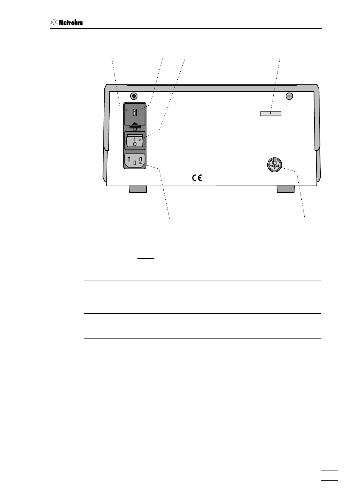
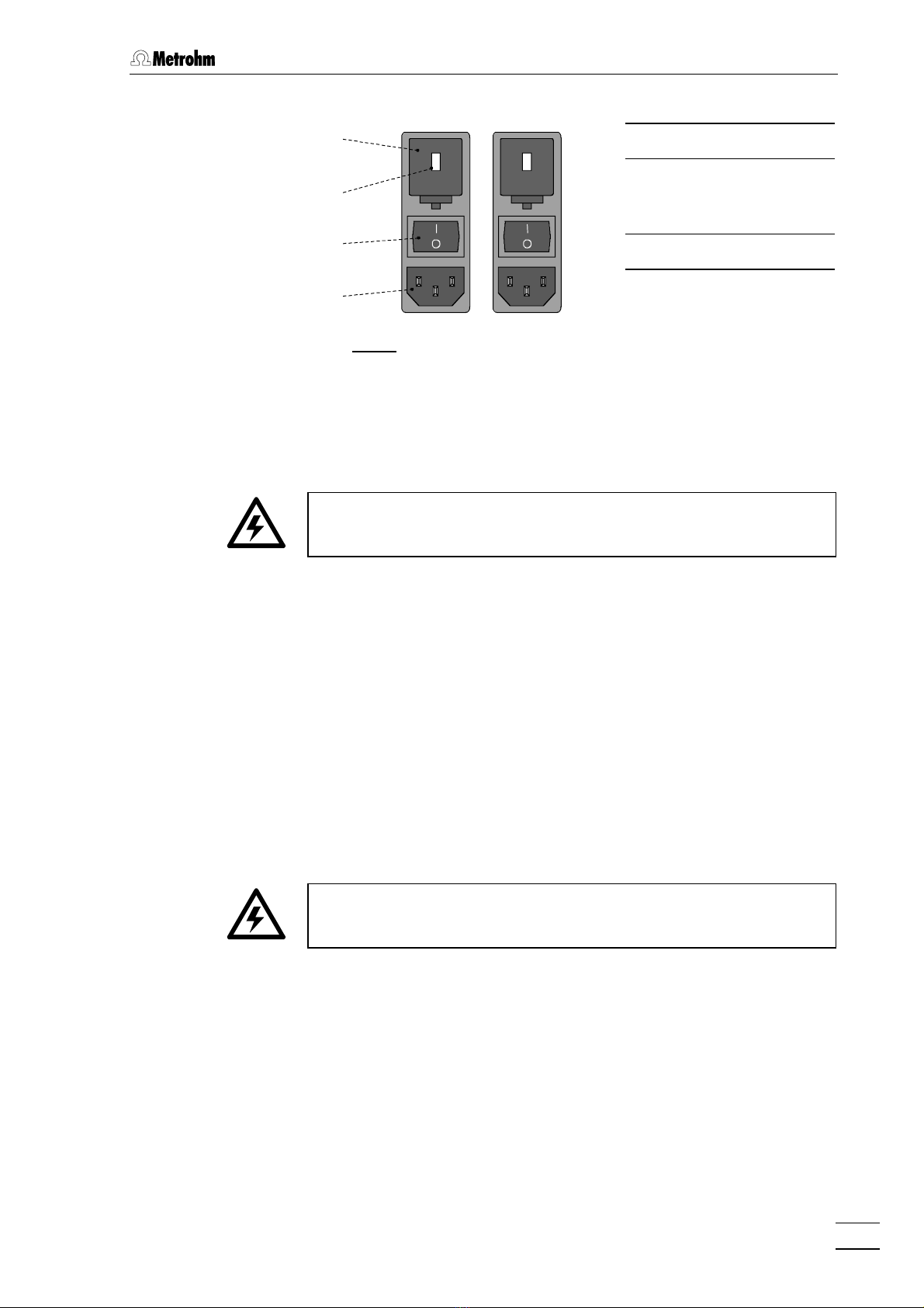
Fig. 2: Rear of 782 IC Column Thermostat
77 Fuse holder
Changing the fuses,
see section 2.2
1010 Serial number
88 Voltage selection insert with
display of voltage 1111 Connection for IC Column
Heater
99 Mains switch
For switching the instrument
on/off:
I = ON 0 = OFF
1212 Mains connection plug
Mains connection see section 2.2
1 Introduction
782 IC Column Thermostat
4
1.3 Information about the Instructions for Use
Please read through these Instructions for Use carefully before you put
the 782 IC Column Thermostat into operation. The Instructions for Use
contain information and warnings to which the user must pay attention
in order to assure safe operation of the instrument.
1.3.1 Organization
These 8.782.1003 Instructions for Use for the 782 IC Column Ther-
mostat provide a comprehensive overview of the installation, startup
procedure, operation, and technical specifications of this instrument.
The Instructions for Use are organized as follows:
Section 1 Introduction
General description of instruments, parts and controls
and safety notes
Section 2 Installation
Mains connection, connection of IC Column Heater
Section 3 Operation
Manual operation
Section 4 Appendix
Technical data, standard equipment, options, warranty,
declarations of conformity, index
To find the required information on the instruments please use either
the Table of contents or the Index at the back.
1.3 Information about the Instructions for Use
782 IC Column Thermostat 5
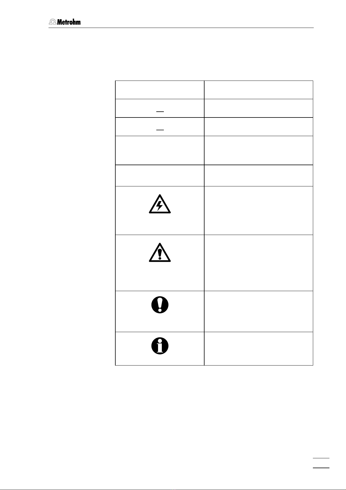
1.3.2 Notation and pictograms
The following notations and pictograms (symbols) are used in these In-
structions for Use:
1212 Part or control of 782
2626 Part or control of 732/733
3333 Part or control of 761
range Menu item, parameter or entry
value of 761
<OK> Button of 761
Hazard
This symbol draws attention to a
possible danger to life or of injury if
the associated directions are not
followed correctly.
Warning
This symbol draws attention to
possible damage to instruments or
instrument parts if the associated
directions are not followed cor-
rectly.
Caution
This symbol marks important infor-
mation. First read the associated
directions before you continue.
Comment
This symbol marks additional in-
formation and tips.
1 Introduction
782 IC Column Thermostat
6
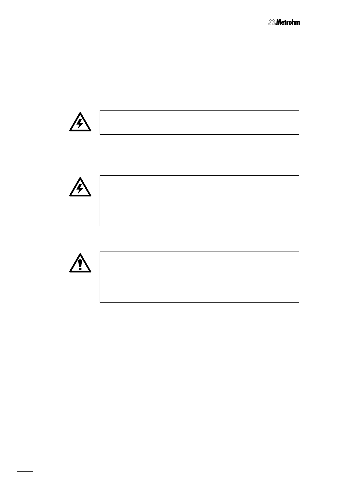
1.4 Safety notes
While electrical safety in the handling of the 782 IC Column Thermostat
is assured in the context of the specifications IEC 1010-1 (protection
class 1, degree of protection IP40), the following points should be
noted:
• Mains connection
Setting the mains voltage must be effected in accordance with the
instructions in section 2.2.
• Opening the instrument
Inside the instrument there are no parts which must be set or adjusted
by the user.
If the 782 IC Column Thermostat is connected to the power supply,
the instrument must not be opened nor must parts be removed from
it, otherwise there is a danger of coming into contact with compo-
nents which are live. Hence, always disconnect the instrument from all
voltage sources before you open it and ensure that the mains cable
is disconnected from mains connection 1212 !
• Protection against static charges
Electronic components are sensitive to static charging and can be
destroyed by discharges. Before you touch any of the components
inside the 782 IC Column Thermostat, you should earth yourself and
any tools you are using by touching an earthed object (e.g. housing of
the instrument or a radiator) to eliminate any static charges which
exist.
2.1 Setting up the instrument
782 IC Column Thermostat 7
2 Installation
2.1 Setting up the instrument
2.1.1 Packaging
The 762 IC Interface is supplied together with the separately packed
accessories in special packagings containing shock-absorbing foam
linings designed to provide excellent protection. The instrument itself is
packed in an evacuated polyethylene bag to prevent the ingress of
dust. Please store all these special packagings as only they assure
transport of the instrument free from damage.
2.1.2 Check
After receipt, immediately check whether the shipment is complete and
has arrived without damage (compare with delivery note and list of
accessories in section 4.2). In the case of transport damage, see
instructions in section 4.4.1 "Warranty".
2.1.3 Location
Position the instrument in the laboratory at a location convenient for op-
eration, free from vibrations and protected against a corrosive atmos-
phere and contamination by chemicals.
2.1.4 Arrangement of the instruments
The 782 IC Column Thermostat can be piled up together with other IC
instruments (e.g. 732, 733, 709).

2 Installation
782 IC Column Thermostat
8
2.2 Mains connection
Follow the instructions below for connecting to the power supply. If
the instrument is operated with the mains voltage set wrongly and/or
wrong mains fuse there is a danger of fire!
2.2.1 Setting the mains voltage
Before switching on the 782 IC Column Thermostat for the first time,
check that the mains voltage set on the instrument (see Fig. 3) matches
the local mains voltage. If this is not the case, you must reset the mains
voltage on the instrument as follows:
1Disconnect mains cable
Disconnect mains cable from mains connection plug 1212 of the
782 IC Column Thermostat.
2Remove fuse holder
Using a screwdriver, loosen fuse holder 77 and take out com-
pletely.
3Change mains voltage
Completely remove voltage selection insert 88 by hand, rotate it
through 180° and reinsert it. The required mains voltage (115 or
230 V) must now be visible from the front.
4Check fuses
Carefully take both fuses out of fuse holder 77 and check their
specifications:
100……120 V 0.5 A (slow-blow) Metrohm-No. U.600.0013
220……240 V 0.25 A (slow-blow) Metrohm-No. U.600.0010
5Insert fuses
Change both fuses if necessary and reinsert in fuse holder 77.
6Install fuse holder
Push fuse holder 77 back into the opening of the 782 IC Column
Thermostat by hand until it clicks into place properly.
2.2 Mains connection
782 IC Column Thermostat 9
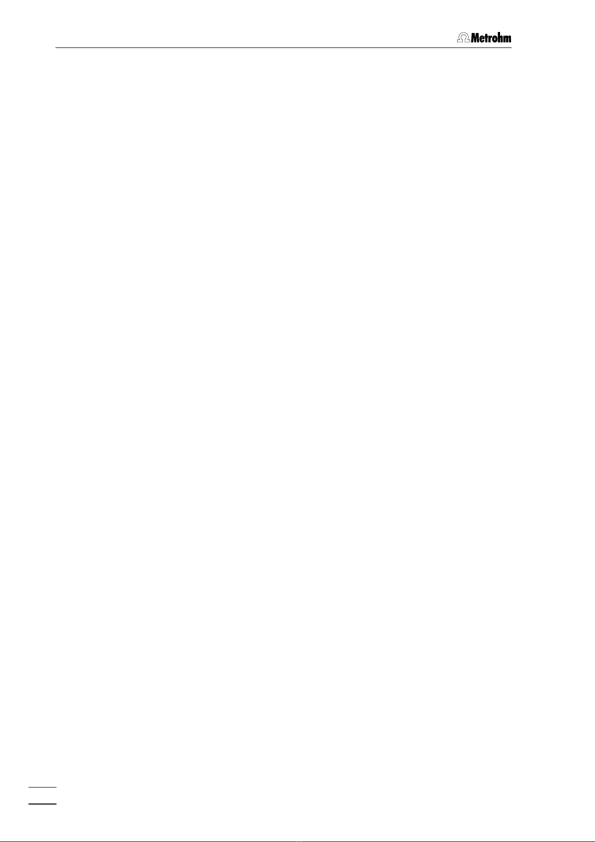
88
99
1212
230
77
115
Fig. 3: Setting the mains voltage
2.2.2 Fuses
Two fuses 0.5 A/slow-blow for 100…120 V or 0.25 A/slow-blow for
220…240 V are installed in the fuse holder 77 of the 782 IC Column
Thermostat as standard.
Ensure that the instrument is never put into operation with fuses of
another type, otherwise there is danger of fire!
For checking or changing fuses, proceed as described in section 2.2.1.
2.2.3 Mains cable and mains connection
Mains cable
The instrument is supplied with one of three mains cables
• 6.2122.020 with plug SEV 12 (Switzerland, …)
• 6.2122.040 with plug CEE(7), VII (Germany, …)
• 6.2133.070 with plug NEMA 5-15 (USA, …)
which are three-cored and fitted with a plug with an earthing pin. If a
different plug has to be fitted, the yellow/green lead (IEC standard)
must be connected to protective earth (protection class 1).
Any break in the earthing inside or outside the instrument can make it
a hazard!
Mains connection
Plug the mains cable into mains connection plug 1212 of the 782 IC Col-
umn Thermostat (see Fig. 3).
2.2.4 Switching the instrument on/off
The 782 IC Column Thermostat is switched on and off using mains
switch 99. When the instrument is switched on the two temperature dis-
plays 55 and 66 light up.
100 – 120 V220 – 240 V
77 Fuse holder
88 Voltage selection
insert with display
of voltage
99 Mains switch
1212 Mains connection
plug

2 Installation
782 IC Column Thermostat
10
2.3 IC Column Heater
2.3.1 Installation in 733 IC Separation Center
Proceed as follows to insert the 2.782.0100 IC Column Heater into the
733 IC Separation Center:
1Switch off all instruments
• Switch off 782 IC Column Thermostat and 732 IC Detector
using the mains switch.
2Insert IC Column Heater
• Unscrew the four knurled screws 3434 from the top rear panel
3535 of the 733 IC Separation Center and remove rear panel
(see Fig. 5 of 732/733 Instructions for Use).
• Position the IC Column Heater in the inner compartment and
insert the cable permanently attached in opening 2929 or 3333 of
the rear panel 3535.
• Replace rear panel 3535 and screw to the 733 IC Separation
Center using the four knurled screws 3434.
3Connect column to injector
• Mount a 6.2744.014 compression fitting on each side of the
6.1836.000 preheating capillary (procedure see section 2.5.3
of 732/733 Instructions for Use).
• Connect the long, free end of the 6.1836.000 preheating
capillary to connection "4" of the injection valve 6868 (see
Fig. 16 or Fig. 17 of 732/733 Instructions for Use).
• Connect the short, free end of the 6.1836.000 preheating
capillary to the inlet end of the separating column 7676 (note
flow direction).
4Rinse column
• Place a beaker beneath the column outlet.
• Switch on 709 IC Pump and rinse column with eluent for ca.
10 min.
• Switch off 709 IC Pump.
5Connect column to detector block or suppressor
module
• without suppressor module:
Screw outlet end of separating column 7676 to the inlet capillary
8282 permanently mounted on the detector block 8181.
• with suppressor module:
Screw outlet end of separating column 7676 to suppressor inlet
capillary 8989 using a 6.2744.010 compression fitting.

2.3 IC Column Heater
782 IC Column Thermostat 11
6Insert column in IC Column Heater
• Remove cover of IC Column Heater.
• Insert separating column with inlet and outlet capillaries into
the IC Column Heater in such a way that the outlet end of the
separting column is at the connecting cable side.
• Insert inlet and outlet capillaries in the slices made for them
and close IC Column Heater with the cover.
7Fix IC Column Heater
• Insert the two 6.2027.060 holders in the mounting rails 8383
(see Fig. 16 or Fig. 17 of 732/733 Instruction for Use) and
fasten IC Column Heater in the holder so that the connecting
cable is on the upper side.
8Connect IC Column Heater
• Plug the connecting cable permanently attached to the IC
Column Heater into connection 1111 "IC Column Heater“ of the
782 IC Column Thermostat (see Fig. 2).
2.3.2 Installation in 761 Compact IC
Proceed as follows to insert the 2.782.0100 IC Column Heater into the
761 Compact IC:
1Switch off all instruments
• Switch off 782 IC Column Thermostat and 761 Compact IC
using the mains switch.
2Insert IC Column Heater
• Unscrew the four knurled screws 1515 from the top rear panel
1717 of the 761 Compact IC and remove rear panel (see Fig. 2
of 761 Instructions for Use).
• Position the IC Column Heater in the inner compartment and
insert the cable permanently attached in one of the openings
1111 of the rear panel 1717.
• Replace rear panel 1717 and screw to the 761 Compact IC
using the four knurled screws 1515.
3Connect column to injector
• Mount a 6.2744.014 compression fitting on each side of the
6.1836.000 preheating capillary (procedure see section 2.5.3
of 761 Instructions for Use).
• Connect the long, free end of the 6.1836.000 preheating
capillary instead of the column connection capillary 2828 at the
injection valve 3232 (see Fig. 14 of 761 Instructions for Use).
• Connect the short, free end of the 6.1836.000 preheating

2 Installation
782 IC Column Thermostat
12
capillary to the inlet end of the separating column 8181 (note
flow direction).
4Rinse column
• Place a beaker beneath the column outlet.
• Open software window for manual system control.
• If necessary, modify Flow rate to the value suited for the
inserted separting column and click on <Send to unit> to send
this value to the 761 Compact IC.
• Switch on high-pressure pump (IC pump) by clicking <On> and
rinse column with eluent for ca. 10 min.
• Switch off high-pressure pump by clicking <Off>.
5Connect column to detector block or suppressor
module
• without suppressor module:
Screw outlet end of separating column 8181 to the inlet capillary
4545 permanently mounted on the detector block 4646.
• with suppressor module:
Screw outlet end of separating column 8181 to suppressor inlet
capillary 9696 using a 6.2744.010 compression fitting.
6Insert column in IC Column Heater
• Remove cover of IC Column Heater.
• Insert separating column with inlet and outlet capillaries into
the IC Column Heater in such a way that the outlet end of the
separting column is at the connecting cable side.
• Insert inlet and outlet capillaries in the slices made for them
and close IC Column Heater with the cover.
7Fix IC Column Heater
• Insert the two 6.2027.060 holders in the mounting rails 2727
(see Fig. 14 of 761 Instruction for Use) and fasten IC Column
Heater in the holder so that the connecting cable is on the
upper side.
8Connect IC Column Heater
• Plug the connecting cable permanently attached to the IC
Column Heater into connection 1111 "IC Column Heater“ of the
782 IC Column Thermostat (see Fig. 2).

3 Operation
782 IC Column Thermostat 13
3 Operation
Switch instrument on/off
The 782 IC Column Thermostat is switched on and off using
mains switch 99 (see Fig. 2) on the rear of the instrument:
IInstrument switched on
0Instrument switched off
After the instrument has been switched on the two tempera-
ture displays 55 and 66 light up and show that the instrument is
ready for use.
Set temperature
The desired heating temperature is set using the two keys 22
and 33. A single pressing of these keys increases or de-
creases the temperature value shown in the lower display 55
in green by 0.1 °C, continuous pressing of these keys leads
to a continuous increase or decrease. A temperature set
once will be preserved even after switching the instrument
off.
Control temperature
As soon as the instrument is switched on the IC Column
Heater is heated to the set temperature. The current
temperature is shown in the upper display 66 in red, the set
temperature is shown in the lower display 55 in green.
3 Operation
782 IC Column Thermostat
14

4.1 Technical data
782 IC Column Thermostat 15
4 Appendix
4.1 Technical data
Temperature control
Temperature range 30…75 °C, to be set in steps of 0.1 °C
Accuracy ±0.5 °C
Stability ±0.2 °C
Mains connection
Mains voltage 115 V: 100...120 V ±10 %
230 V: 220...240 V ±10 %
Switchable with voltage selection insert in fuse
holder (see section 2.2.1)
Mains frequency 50...60 Hz
Power consumption 12 VA
Fuse 5 mm Ø, 20 mm length
100…120 V: 0.5 A (slow-blow)
220…240 V: 0.25 A (slow-blow)
Safety specifications
Construction / Testing According to IEC 1010 / EN 61010 / UL 3101-1,
protection class 1, degree of protection IP40
Safety directions The Instructions for Use include information and
warnings to which the user must pay attention in
order to assure safe operation of the instrument.
Electromagnetic compatibility (EMC)
General requirements Standards met:
IEC61326/EN61326, NAMUR
Emitted interference Standards met:
EN55011, EN55022, EN 50081-1/2
Immunity to interference Standards met:
IEC61000-4-2/EN61000-4-2 (class 4),
IEC61000-4-4/EN1000-4-4 (class 4),
IEC61000-4-11/EN61000-4-11,
IEC61000-4-14/EN61000-4-14,
IEC61000-6-2/EN61000-6-2,
EN50082-1/2

4 Appendix
782 IC Column Thermostat
16
Ambient temperature
Nominal operating range +5…+45°C
(at 20…80 % atmospheric humidity)
Storage, transport –40…+70°C
Housing
Material of cover Polyurethane rigid foam (PUR) with fire protection
for fire class UL94VO, CFC-free
Material of base Steel, enamelled
Dimensions
Width 255 mm
Height 128 mm
Depth 340 mm
Weight 4.4 kg (incl. accessories)

4.2 Standard equipment
782 IC Column Thermostat 17
4.2 Standard equipment
Subject to changes !
All dimensions are given in mm.
The 2.782.0010 IC Column Thermostat includes the following parts:
Quant. Order No. Description
11.782.0010 Control unit "IC Column Thermostat"
11.782.0100 IC Column Heater
16.1836.000 Preheating capillary
Length = 0.8 m
16.2027.060 Holder
to fix the IC Column Heater in the inner
compartment of the 733 IC Separation
Center or 761 Compact IC
Opening d = 37 mm
Set of 2
16.2122.0X0 Mains cable
to customer's specifications:
Cable socket Cable connector
Type IEC 320/C 13 Type SEV 12 (CH…)...............................6.2122.020
Type IEC 320/C 13 Type CEE (7), VII (D…)...........................6.2122.040
Type CEE (22), V Type NEMA 5-15 (USA…)......................6.2122.070
16.2744.014 PEEK compression fitting
For connection of 6.1831.010 PEEK
capillaries or 6.1803.020 PTFE capillar-
ies.
Set of 2
18.782.1003 Instructions for Use (English)
for 782 IC Column Thermostat
1.59
0.25
Table of contents


