Raychem TA User manual

© Tyco Thermal Controls INST-264 PCN 1244–002938 Rev.1 06/09 Printed in Belgium on recycled paper
TA
Basic Thermostat
Thermostat operation and user manual

English: Floorheating thermostat ............................ 4
Operation and user manual
Deutsch: Fußbodenheizung .......................................... 22
Installation und Betrieb
Français: Chauffage par le sol .................................... 40
Guide d’installation et d’utilisation
Nederlands: Vloerverwarming ........................................... 58
Installatie en bediening
Norsk: Gulvvarme ......................................................... 76
Installasjon og anvendelse
Svenska: Golvvärme ......................................................... 92
Installation och användning
Dansk: Gulvvarme .........................................................110
Installation og betjening
Suomi: Intellis –termostaatti ...................................126
lattialämmitykselle
Asennus- ja käyttöohje
Polski:
Instrukcja termostat
........................................142
montażu i obsługi
Русский:
Системы подогрева полов
.........................160
Инструкция по монтажу и эксплуатации

3
70,
60
70,
60
82
82 33
54
21
54
33
70,
60
∅ 60
62
56
Fig. 1
Fig. 2

4
English
1. Technical specification ............................................................... 5
2. Description ..................................................................................... 6
3. Mounting and installation ......................................................... 7
4. Operation ........................................................................................ 9
4.1 Getting started .................................................................... 9
4.2 Optional functions .............................................................. 12
4.2.1 Heat Booster ............................................................ 12
4.2.2 External set back .................................................... 13
4.2.3 Lock ............................................................................. 13
4.2.4 Summer Mode (Heating Off)............................. 13
4.3 Installer's menu................................................................... 14
4.3.1 Menu 1: Measured temperature ...................... 15
4.3.2 Menu 2: Temperature calibration .................... 15
4.3.3 Menu 3: Delayed start-up ................................... 17
4.3.4 Menu 4: First warming function ...................... 17
4.3.5 Menu 5: Heating running time.......................... 19
5. Trouble shooting............................................................................. 19
5.1 Error Codes .......................................................................... 19
5.2 Floor sensor resistances ................................................ 20
6. Factory settings ............................................................................. 20

5
1. Technical specifications
Supply voltage 230VAC, +10%,–15%,
50/60 Hz
Power consumption, average 4 VA
Main power switch 2-pole 16A
Relay output - heating cable 230V, max. 13A
Ambient temperature – operation 0 +40°C
Ambient temperature – transport –20 +50°C
Temperature range, floor sensor +5 +35°C
Temperature range, room sensor +5 +40°C
Accuracy – floor/room sensor +/– 0,5°C
Switching hysteresis 0,5°C
Control modes Floor sensor or room
sensor
Optional external control Set back function –3.5°C
Back-up for set values In non-volatile memory
Protection class IP 21
Terminals Max. 2,5 mm2
Floor sensor NTC, 10K / 25°C.
with 3 m cable
Maximum lenght of floor 100 m, 2 x 1,5 mm2 (min.)
sensor cable (230VAC cable type)
Dimension with frame (Fig.1) H 82 x W 82
x D 54 mm
Colour Polar white RAL 9010
Approvals Semko, NF, eu.bac, CE

6
2. Description
TA is a basic thermostat specially designed for underfloor
heating. It provides the following features and functions:
• Electrical floor heating control by means of an external
floor sensor or integrated room sensor.
• Load capacity of the thermostat, 13A/230Vac (3000W)
• 2-pole main power switch
• External set back
Extra terminal which can be used as an external closing
contact to reduce the set temperature by 3,5°C
• Heat Booster
The set temperature can be increased by 5°C for 2 hours.
Reverts automatically to the original temperature setting
• Possible to lock and unlock all possible settings for the
thermostat at the touch of the buttons
• Monitoring of the floor or room sensor. Display indication
and cut off the heating output during sensor fault (fail-
safe)
• First Warming function for gradual warming of new
screed
• Enclosure protection class IP21 as standard
• Floor sensor with 3 meters of cable included
• Delayed Start-Up
• Summer Mode (Heating Off)
• The thermostat is supplied with an assembly frame and a
front for the ELJO Trend / B&J Jussi / Merten (Plan,
Smart, Arc, Atelier, M1, Antik, Termo, M-Star) / Jung (CD,
LS, AS) / Gira (ST55 Standard, E2) wall box system. An
extra front for the square sized frames such as ELKO RS
is also included
• Approved by SEMKO,NF, eu.bac, CE-marked

7
3. Mounting and installation
Thermostat
TA is intended for flush mounting in a standard 65 mm
wallbox. It should be positioned approximately 1,5 metres
above the floor, protected from direct sunlight and draughts.
All electrical conduits passing into the thermostat box that
contain cables must be sealed to protect the thermostat
against any draughts, e.g. with a piece of insulation in the
conduit outlet.
TA can also be mounted in an external wall box. If the
thermostat will be mounted on a rough wall surface, e.g.
bricks, put a string of silicon glue under the top frame.
Assembly frame and front can be exchanged by pushing
with a screw driver on two knobs, placed on the sides of the
thermostat. (Fig. 2)
Floor sensor
The floor sensor should be installed in a separate flexible
conduit/hose for easy replacement. For best control
performance, position the floor sensor between two heating
cables as close as possible to the top floor surface. Do not
position the floor sensor tip closer than 3 cm to the heating
cable.
The floor sensor cable can be extended to 100 m with a
separate standard installation cable 2 x 1.5 mm2(min.)
(230VAC). In order to avoid signal disturbance resulting
in a possible malfunctioning of the thermostat, the sensor
should not be installed in a conduit together with other
power carrying cables.
Connection of the thermostat
The thermostat must be connected to 230VAC according to
the circuit diagrams. When connecting multiple heaters to
the thermostat where the combined total load is above 13A,
you are required to use a contactor or switchgear.
If the protective earth terminal, (PE) on the thermostat is
used, the incoming power cable to the heating cable shall be
connected to the common earth terminal on the thermostat,
otherwise a separate terminal connection block (not
included) must be used.

8
Product specific information for use with floorheating
systems
• Use with T2QuickNet:
The T2QuickNet product line is approved with the
thermostat working in floor sensor mode. Be aware that
the floor sensor must be installed and activated for an
installation with T2QuickNet.
• Use with T2Red (T2Reflecta) self-regulating systems:
Self-regulating heating cables have an inrush current
at start up. In order to guarantee the life time of the
thermostat, the maximum load of the self-regulating
application in nominal conditions is limited to 10A.
A 13A self-regulating load will reduce the life time of the
relay contacts.
Direct, connection – e.g. single heating circuit
Remote set
back signal
Power supply
230 VAC
Floor
sensor
FP
L
N
10K
NTC
PE
SENSOR
N
LN
L
LNPE
PE
Heating cable
230 VAC
Max.13A

9
Connection via contactor – e.g. 3 heating circuits
4. Operation
4.1 Getting started
Thermostat controls
FP
10K
NTC
SENSOR
N
LN
L
K1 A2
A1
135
246
LLL
PE
NNN
LNL1 L2 L3 N PE
Remote set
back signal Power supply
230 VAC
Floor
sensor Power supply to
heating cables
A
B
C D
A: main power switch
B: OK/accept
C: “–” down
D: “+“ up

10
Display symbols
Set value for floor- or room temperature
or error code
Heating on
Error
Locked settings
Calibration mode
Menu number
Manual mode
Auto mode
Heat booster active
Floor- or Room sensor mode
(in room sensing mode <>is not shown)
Note: the square moves over the different symbols when
programming. The symbol in the square indicates the active
function: manual mode, automatic mode by external signal,
booster function.
First start – set the thermostat in operation :
Push in the main < > power switch, located on the upper
part of the thermostat.
The display illuminates and shows all segments. Then it
shows the setting temperature and sensor mode. The sensor
mode is initialised automatically. If the floor sensor cable
is connected, it operates in floor sensor mode. If the floor

11
sensor cable is not connected, it operates in room sensor
mode.
After 5 sec. the thermostat checks if an external control
signal is connected.
If yes, the thermostat will be controlling according to the
set temperature and external signal. The symbol AUTO is
activated. If not, the thermostat will be controlling according
to the set temperature.
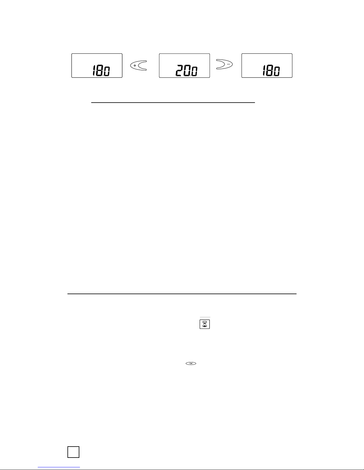
Adjust the set temperature, desired floor temperature or
room temperature, with the < > buttons. This is an
approximate set value to get a comfort temperature on the
floor or in the room.
Heating-on symbol < > indicates on the display when the
heating cable is on.
Learning Function
This function starts only if the thermostat has no floor
sensor connected, (‘Er3’ at start-up) only in ambient sensing
mode configuration.
At the first thermostat power-up (or after a factory reset),
the thermostat begins its own regulation parameter
calibration.
During this learning time, the user doesn’t have access to
ambient temperature:
Instead of temperature, a count down timer
from 2.1 hours to 0.1 hour
(0.1 hour = 6 minutes) is displayed.
The learning time is divided into two steps:
1. Time < 30min (0.5 hour) [ from 2.1h to 1.6h]:
the first half hour, the user is allowed to change
the set temperature and activate the floor warming
system. This period can be used by the
12
installer to check the floor warming system
installation. The set temperature can be adjusted
by using +/- keys.
2. 30min < Time < 2hours [from1.6h to 0.1h]:
The thermostat doesn’t take into account the set
temperature. But during this period, the thermostat
can power on and off the floor warming system to
adjust its regulation parameters.
If there is a main power supply loss during this learning
period (main switch off or power supply failure), the
thermostat will restart the learning function.
At the end of this learning function, the thermostat is
automatically calibrated (adapted to the load linked to
the thermostat):
Internal offset
Compensation
This function will run at every factory reset of the
thermostat.
4.2. Optional functions
4.2.1 Activating Heat booster < >
This function is used for temporary increase of the floor/
room temperature by 5°C.
Push the confirmation button < > for 3 sec. The current
set temperature will increase by 5°C for 2 hours and this
increased temperature is shown on the display. Automatic
reverts to the set temperature after 2 hours or if the
confirmation button is pushed again for 3 sec. within the 2
hour period.
°c
°c
°c
+
+

13
If external control is connected: Push the confirmation
button < > for 3 sec. The thermostat will now be in
Manual mode. Push again the confirmation button < >
for 3 sec. The thermostat will go in “booster” mode and the
current set temperature will increase by 5°C for
2 hours. This increased temperature is shown on the
display. Automatic reverts to the set temperature after
2 hours or if the confirmation button < > is pushed
again for 3 sec. within the 2 hour period.
4.2.2 External set back
To utilise the set-back function and reduce the current set
point by 3.5°C: Connect a closing contact between the FP
terminal and phase terminal e.g. a closing timer switch.
When the contact is closed, the symbol "P" is displayed in
the upper left corner indicating activation.
To enable manual control mode: Push the confirmation
button in 3 sec. Normal set temperature control is active.
Push again the confirmation button < > in 3 sec. for
leaving the Manual mode to Booster mode. Push the
confirmation button
< > again 3 sec to go the AUTO mode.
4.2.3 Lock
Lock and unlock the thermostat
It is possible to lock all the settings for the thermostat. (eg
public buildings)
Lock: Push simultaneously < > and < > and < >
The key symbol is displayed when the thermostat is locked.
Unlock: Push simultaneously < > and < > and < >
4.2.4 Summer Mode (Heating Off)
Normal Menu:
In both case (floor or room sensing mode) the temperature
seen on the thermostat correspond to the room temperature.
In room sensing mode, the user sees the temperature
measured by the thermostat (Room Temperature)
14
In floor sensing mode, the user sees the room temperature
Floor temperature [Installer menu n°1]
– Offset [Installer menu n°2]
= Room temperature (seen on the thermostat)
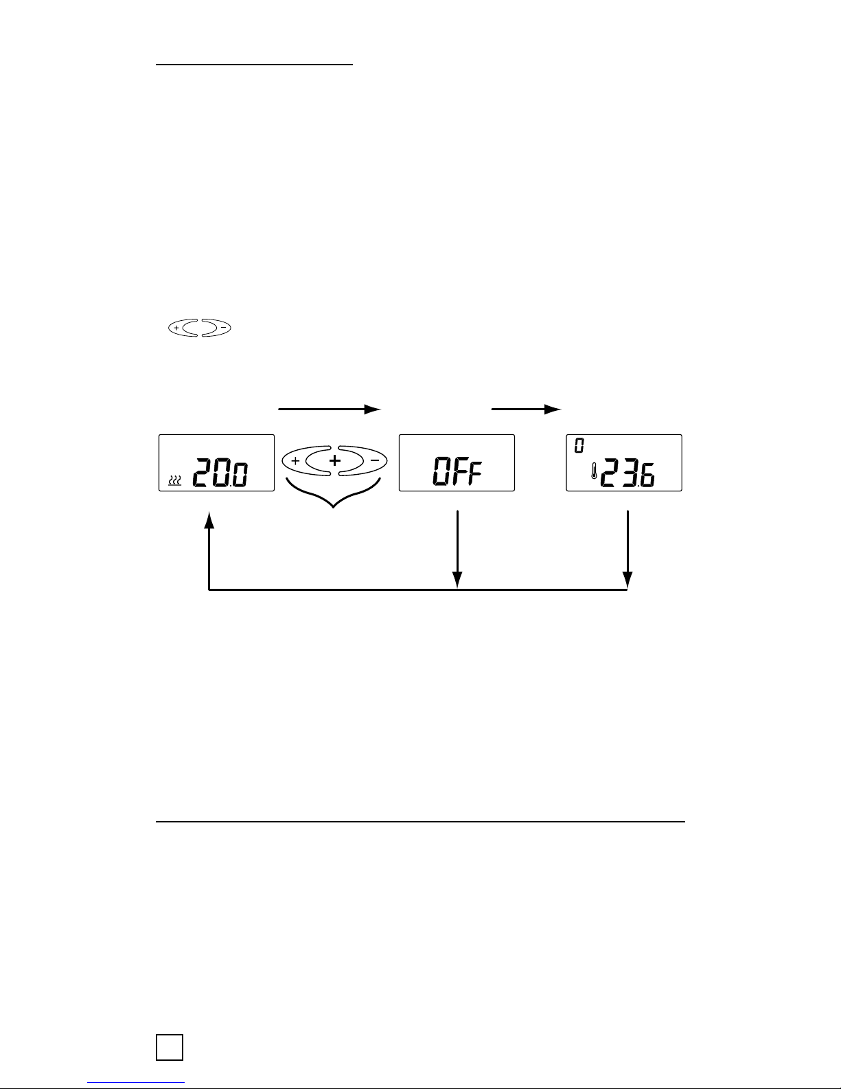
The thermostat has an ‘OFF mode’. In this stand-by mode,
the floor heating is not powered at all. The thermostat
screen will display the actual measured room temperature.
In the summer time, in this 'OFF mode', the thermostat acts
as a thermometer only.
To go to the ‘OFF mode’ press simultaneously the
< > keys for more than 1 second. Repeat this step to
exit this mode.
The off mode is available only after the end of the first
warming function and after the learning function. When one
of these functions is in progress the thermostat can power
up the floor warming system even if the thermostat is in off
mode.
4.3 Installer's menu
If the desired temperature is not reached or if there is a
difference between real floor/room temperature and the set
value on the display, calibrate the thermostat.
Push and hold OK button for 6 seconds to enter following
Menu:
°c
°c
Normal mode OFF mode
5s after OFF mode with
tempertaure view
Pressed simultaneously
for more than 1s
To come back to
normal mode

15
• Menu 1: < > read-out actual measured temperature
• Menu 2: < > calibration of the floor/room temperature
4.3.1 Menu 1: Temperature viewing
• Room sensing mode: Room temperature viewing
(temperature measured inside the thermostat)
• Floor sensing mode: Temperature inside the cement
slab
To check the actual measured temperature, push the
confirmation button for 6 sec.
In menu number 1 the
measured temperature value is
indicated on the display:
in-floor temperature in case of
floor sensing mode < >.
This value can be used to calibrate the floor surface
temperature value to the set temperature value on the
display. Push confirmation button several times (scroll
through Menu structure) for leaving the Configuration mode
to Normal mode
4.3.2 Menu 2: Temperature calibration
Calibration of the temperature set value
After stable temperature in
floor: The set temperature
value can be calibrated against
the real floor / room
temperature. This needs to be
done using a separate
thermometer for determining the actual floor or room
temperature. The thermometer should be put on the floor
surface, sensing the floor surface temperature, or on the
wall sensing the air temperature.

16
Calibration of room sensor mode < >:
In room sensor mode the internal sensor value is the same
as for the set value on the display.
Push the confirmation button < > in 6 sec. to enter the
Configuration mode.
Push the confirmation button < > to enter menu
number 2.
Change the temperature value via < > buttons to the
same value shown on the reference wall thermometer.
Push confirmation button several times (scroll through
Menu structure) for leaving the Configuration mode to
Normal mode
• Room sensor: Room temperature blinking and possibility
to adjust the room temperature with +/- keys.
Initial value to calibrate
Calibration of floor sensor mode < >:
In floor sensor mode there is a default offset value of +4°C
between the infloor sensor value and the floorsurface value
(which is the set value on the display). The read-out value in
Menu 1 can be used for set value calibration.
Push the confirmation button < > in 6 sec. to enter the
Configuration mode.
Push again the confirmation button < > to enter menu
number 2.
Change the offset value via < > buttons so that the
set temperature value will be approx. the same value shown
on the reference floor surface thermometer.
• Floor sensor: the user can adjust the difference between
the temperature inside the floor and the room temperature.
Offset = Floor temperature – Room temperature
+
+
+
+

17
New offset = Tmenu 1 - Tsurface
Example: Use the floor sensor temperature value from menu
1. If this value is 27°C and the floor surface thermometer
shows 24°C, the new offset value will be 27-24 = 3.
Change the offset from 4°C to 3°C.
Push confirmation button several times (scroll through
Menu structure) for leaving the Calibration mode to Normal
mode
4.3.3 Menu 3: Delayed Start-Up
The user can choose the time before powering up the floor
warming system.
Possible values: from 0 [OFF] to 15 minutes [15 ’]. A "t"
is shown on in the display when the delayed start-up is
switched on.
4.3.4 Menu 4: First warming function
Possible values: [OFF] or [ON]
This function does not apply by default (Installer menu
number 4: OFF by default, factory value = OFF).
Tsurface
Tmenu1
+
+

18
Progressive warming cement slab during 21 days period,
but limited to 20°C.
Working description:
To activate this option the user enters the installer menu
number 4 and selects the configuration (‘on’ or ‘off’) and
validate.
When the thermostat comes back to the normal mode, the
user sees instead of the temperature, the remaining number
of days of the progressive warming (total duration: 21 days).
During this time, the thermostat warming cycle is equal to
24 minutes (60 cycles per day).
The first day, the thermostat powers the
floor heating system during 1 minute on
each 24 min cycle (= 1h of warming the
first day).
The second day, the thermostat powers the
floor heating system during 2 minutes on
each 24 min cycle (= 2h of warming the
second day).
Before the last day, the thermostat powers
the floor heating system during 19 minute
on each 24 min cycle (= 19h of warming
the first day).
The last day, the thermostat powers the
floor heating system during 20 minute on
each 24 min cycle (= 20h of warming the
first day).
Function
remains active
for 21 day.
Function
remains active
for 1 days.

19
If the thermostat regulation works with the floor sensor only,
the cement slab temperature will be limited to 20°C.
If the thermostat regulation works with the room sensor
only, the ambient temperature will be limited to 20°C.
In both cases of power supply failure or main switch put on
‘Off’ position by the user during this function progress, the
thermostat will resume from where it stopped (first warming
function time saved in memory).
This function can be stopped at any time by setting the
installer menu number 4 to ‘OFF’
At the end of this first warming function, the learning
function begins.
4.3.5 Menu 5: Heating Running Time
Running time (the time in the course of which the floor
warming system is powered)
3’ : 3 minutes [0..59] 5h : 5 hours [1..23]
7d: 7 days [1..30] 1m: 1 month [1..99]
5. Trouble shooting
5.1 Error codes
Number Error type
ER 1 Wrong floor sensor (100 kΩ)
ER 2 Short circuit on floor sensor
ER 3 Open circuit on floor sensor
ER 4 Short circuit on room sensor
ER 5 Open circuit on room sensor
ER 6 Other error

20
5.2 Monitoring of the temperature sensor
In the event of damage or malfunction of one of the
temperature sensors, the heating output cuts off (fail safe)
and an errorcode is displayed.
The floor sensor has the following temperature / resistance
values:
15°C / 15,8 kΩ
20°C / 12,5 kΩ
25°C / 10,0 kΩ
30°C / 8,04 kΩ
35°C / 6,51 kΩ
The floor sensor may be replaced by a new one. In the event
of malfunction of the room sensor the entire thermostat
must be replaced.
6. Reset to factory settings.
set value floor sensor mode < > 23°C
set value room sensor mode <>20°C
floor sensor offset value <>4°C
Reset: switch "off" the thermostat < >. Press < > and < >
simultanously with switching "on" < > the thermostat "000" is displayed.
Press < > and “CLR” is displayed. The thermostat is reset.
Table of contents
Languages:
Other Raychem Thermostat manuals


