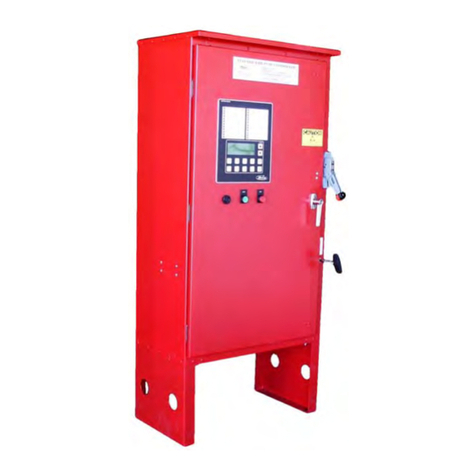
METRON M100 Series User manual

-1-
MANUAL
ELECTRIC FIRE PUMP CONTROLLERS
FOR USE WITH THE MANUAL START FIRE PUMP CONTROLLER
SERIES M100, M200 AND M220 AND THE COMBINED AUTOMATIC-MANUAL
START FIRE PUMP CONTROLLERS SERIES M300, M400 AND M420
TABLE OF CONTENTS
PART I GENERAL DESCRIPTION...................................................................................................PAGE 2
PART II FUNCTIONS..........................................................................................................................PAGE 2
PART III INSTALLATION...................................................................................................................PAGE 3
PARTIV INITIAL INSTALLATION START-UP PROCEDURE ....................................................PAGE 3
PARTV OPERATION OF CONTROLLER........................................................................................PAGE 5
PART VI SEQUENCE OF OPERATION..............................................................................................PAGE 6
PART VII NOMENCLATURE...............................................................................................................PAGE 8
Note: This manual is subject to change without prior notice.
METRON, INC.
1505 West Third Avenue
Denver, Colorado 80223
Telephone: (303) 592-1903 Fax: (303) 534-1947

-2-
PART I: GENERAL DESCRIPTION
The basic function of the Fire Pump Controller is to start the pump motor to maintain the water system pressure. This
may be accomplished in automatic controllers, Series M300, M400 and M420, by automatically starting the pump
motor upon drop in pressure in the water main or from a number of other demand signals. Manual controllers, Series
M100, M200 and M220 must be started manually while the automatic controller can be started automatically or
manually. All can be started by remote manual means, but cannot be stopped remotely. The automatic controller can
be set to stop automatically or require manual stop after an automatic start.
PART II: FUNCTIONS
A. Automatic Starting From:
1. Drop in water line pressure
2. Deluge Valve operation, Option D
3. Loss of remote alarm power, Option P
B. Alarm and Signals:
1. Remote indication of pump operation: One (1) set of normally open (N.O.) and normally closed
(N.C.) contacts located in the controller operate when the pump is running.
2. Loss of power to the controller: One (1) Single Pole Double Throw (SPDT) contact located in the
controller operates for loss of power, loss of phase, or low voltage.
3. Phase reversal of power to controller: One (1) SPDT contact located in the controller operates for
phase reversal of the power to the controller.
4. Motor current exceeds 125% of normal: One (1) SPDT contact located in the controller operates
when the motor current exceeds 125% of normal.
5. Power On pilot light on controller: This light is on whenever both the isolation switch and circuit
breaker of the controller are closed indicating that power is available and the controller is set for
operation.
6. Phase reversal pilot light: This pilot light is on whenever there is a phase reversal of the power to
the controller.
7. Engine Lockout (Option E): When an engine drive system is used as a backup a N.O. auxiliary
contact on the motor contactor is provided to prevent the engine from starting if the electric motor
isrunning.
8. Electric Motor Lockout (Option M): The electric motor lockout is generally used in conjunction
with engine lockout above. If the engine is running due to a power outage, or other reasons, the
electric motor can be locked out until the engine is stopped.
C. Sequential Starting (Option S): This optional feature is provided for multiple fire pump installations. This
provision times the start of the pump motors by a preset time interval so that all motors do not come on at
once.
D. Principal Components of Controller:
1. Isolation Switch
2. Circuit Breaker
3. OvercurrentMonitor
4. Contactor
5. Pressure Switch
The incoming line is connected directly to the isolation switch. From there the power is fed to the circuit
breaker and then to the contactor. Both the isolation switch and circuit breaker are normally closed. The
contactor is operated either manually or automatically to start the motor.

-3-
PART III: INSTALLATION
The Fire Pump Controller has been assembled and wired at the factory with the highest workmanship standards. All
wiring and functions have been thoroughly tested to assure correct operation when properly installed. Before
operating the controller, perform the Initial Installation Start-Up Procedure, Part IV.
The cubicle should be well grounded according to local standards. Make sure that all applicable external control
wires are connected to appropriate terminals as shown in External Hookup drawing. If the controller is supplied with
Option "D" Deluge Valve Start, and it is not being used the terminals for this must be jumpered (See External Hookup
drawing). Failure to make the proper connections will cause the controller to malfunction. Connection from the
contactor to the motor may be done after the test procedure is completed. The contact ratings of the remote alarm
contacts of the controller are shown on the controller Schematic drawing.
After installation has been completed, perform the Initial Installation Start-Up Procedure, Part IV before operating the
controller.
PART IV: INITIAL INSTALLATION START-UP PROCEDURE
A. General: All but the final test can be made with the motor disconnected. This will eliminate the need for
starting and stopping the motor several times during the test procedure. If the output connections from the
contactor to the motor were made on initial installation, disconnect them for the first part of the Initial
Installation Start-Up Procedure. Referto External Hookup drawing for nomenclature of all controls. Refer to
schematic for location of contacts for remote alarms.
The controls and their functions as follows:
1. Isolation Switch: This switch is connected in the circuit between the line and the circuit breaker.
Its function is to disconnect the main power to the controller.
2. Circuit Breaker: The circuit breaker is located between the motor contactor and the isolation
switch. Its function is to protect the line from damage due to a short in the load.
3. Overcurrent Monitor: The overcurrent monitor (1OCM) senses the motor current through a set of
current transformers (CTs) in the controller. When the motor current exceeds 125% of normal a
yellow LED illuminates on the monitor and a set of dry contacts change state. When the motor
current exceeds 300% the monitor begins timing based on how much the current exceeds 300% of
normal and a red LED begins flashing. The greater the current the shorter the time period such that
at 600% of normal the monitor activates in approximately 14 seconds. When the monitor activates
(at the end of timing), a set of normally open contacts close which energize the shunt trip in the
circuit breaker causing it to trip.
4. Emergency Start Lever: This control is used to start the fire pump in case of any malfunction
within the control circuits.
5. Start Button: The pushbutton starts the pump motor by exciting the contactor coil so that it closes.
6. Stop Button: This pushbutton stops the pump motorby opening the contactor coil circuit, thereby
disconnecting the current to the pump motor.
B. Series M100 Manual Non-Automatic:
1. Close isolation switch and measure voltage at output of isolation switch. Voltage should be the
same as incoming linevoltage.
2. Close circuit breaker and measure voltage of input of motor contactor. Voltage should be the same
as in Step 1. Power On pilot light on controller should be on.
3. Push manual start button; motor contactor should close. Measure voltage at output of contactor.
It should be the same as in Step 1.
4. Push stop button. Motor contactor should be open.

-4-
5. Turn circuit breaker off.
6. Connect output from contactor to pump motor.
7. Close circuit breaker.
8. Push start button; motor should start. Check the motor for proper rotation.
9. Push stop button; motor should stop.
C. Series M200 Manual Primary Resistance Start: The start-up procedure is the same for the Series M100.
There are two contactors instead of one and a set of starting resistors. The starting contactor is connected
in series with the resistors to reduce the voltage to the motor for a preset time. After the preset time delay,
the main contactor will close in parallel with the starting contactor and resistors and thus apply full voltage
to the motor. If the motor is not connected for this test, there will be no voltage drop across the resistors
and full voltage will appear at the output terminals of the contactors as soon as the starting contactor
closes.
D. Series M220 Manual Part-Winding Start: The start-up procedure is the same as for the Series M100. There
are two contactors for part-winding start. One contactor will close immediately on demand and the other will
close after a preset time delay. Full voltage will be present at the output of both contactors.
E. Series M300 Combined Manual Automatic:
1. Close isolation switch and measure voltage at output of isolation switch. Voltage should be the
same as incoming line voltage.
2. Close circuit breaker and measure voltage at input of motor contactor. Voltage should be the same
as in Step 1. The Power On pilot light on controller should be on. In addition, the red Phase
Reversal pilot light should not be on. If it is, check that all three phases are present and of the
correct voltage. If all power is correct, turn the controller isolation switch OFF, reverse any two of
the three phase wires connected to terminals L1, L2, or L3, of the power monitor, then turn isolation
switch and circuit breaker back ON. The Phase Reversal pilot light should not be on.
3. Push start button, motor contactor should close. Measure voltage at output of contactor. It
should be the same as the incoming line voltage.
4. Push stop button, motor contactorshould open.
5. Drop water pressure at water inlet to controller so pressure switch will close, motor contactor
should close. Allow water pressure to return to normal. If controller is set for automatic stop, set
running period timer for at least 10 minutes running time. Motor contactor should open after this
time period. If the controller is set for manual stop, push stop button; motor contactor should
open.
6. For controllers supplied with Option D, repeat Step 5, except momentarily open deluge valve switch
instead of dropping pressure to close pressure switch.
7. Turn circuit breaker off.
8. Connect output from contactor to pump motor.
9. Close circuit breaker.
10. Push start button, motor should start. Check the motor for proper rotation.
11. Push stop button, motor should stop.

-5-
F. Series M400 Combined Manual-Automatic Primary Resistance Start: The start-up procedure is the same
as for the Series M300. There are two contactors instead of one, and a set of starting resistors. The starting
contactor is connected in series with the resistors to reduce the voltage to the motor for a preset time. After
this preset time delay the main contactor will close in parallel with the starting contactor and resistors and
thus apply full voltage to the motor. If the motor is not connected for this test, there will be no voltage drop
across the resistors and full voltage will appear at the output terminals of the contactors as soon as the
starting contactor closes.
G. Series M420 Combined Manual-Automatic Part-Winding Start: The start-up procedure is the same as for
the Series M300. There are two contactors for part-winding start. One contactor will close immediately on
demand and the other will close after a preset time delay. Full voltage will be present at the output of both
contactors.
H. Sequential Starting (Option S): The sequential start timers provide a time delay between the pressure
switch contacts closing and the motor contactor closing. Where sequential starting is used, set the
sequential start timers for approximately ten (10) second intervals. Perform Initial Start-Up Procedure for
appropriate controller and check for sequential timing on automatic starts. Sequential starting is bypassed
by manual starting.
PART V: OPERATION OF CONTROLLER
After the installation and test procedure are completed the controller is ready for normal operation.
A. Manual Controller: Isolation switch and circuit breaker should be closed. Controller is now ready for
manual operation. The controller is started by pushing the start button. If for some reason the motor fails to
start when the start button is pushed the emergency manual lever may be moved to the "On" position. This
lever must be manually locked in the "On" position or it will return to "Off" when released. This lever is for
emergency use only.
B. Automatic Controllers / (All Types): The isolation switch and circuit breaker should be closed. For a
sequential start controller and sequential start, timing relay 3TR should be set for approximately ten (10)
second intervals. Local requirements may dictate different time settings. For controllers set for automatic
stop, set the running period timer for at least 10 minutes running time. To activate the automatic stop
feature, the jumper on the Manual Stop Jumper Block must be removed.
C. Emergency Manual Operation: Emergency manual operation is provided in case of failure of control
circuitry. This lever is manually moved to the "On" position and must be manually latched in the "ON"
position or it will return to "Off" when released. The lever should be moved from the "Off" position to the
"On" position in as quickly a motion as possible to prevent burning the contacts. The circuit breaker
should be tripped to disconnect circuit before releasing emergency lever. This lever is for emergency use
only. A mechanical interlock switch is connected to the emergency lever to operate the contactor
electrically when all circuitry is functioning properly. This is provided to prevent inadvertent slow closing
of contactor and burning of contacts.

-6-
PART VI: SEQUENCE OF OPERATION
A. Introduction: The explanation of the sequence of operation will start with the assumption that the controller
has been properly installed, all external connections have been made and the isolation switch and circuit
breaker are closed. In other words, the controller is operational. The Power On pilot light should be on. All
wiring on the primary side of the Transformer 1CPT will be referred to as the primary circuit. All wiring on
the secondary side of the Transformer 1CPT will be referred to as the secondary circuit.
B. Manual Operation:
1. M100, M200 and M220 Manual Controllers: For manual operation there is a start button switch on
the controller and terminals for an optional remote start switch located elsewhere. These switches
have normally open contacts which close to energize 1CR. 1CR locks in on its own N.O. contact
and stays energized until the stop button is depressed. The N.O. contact of 1CR in the primary
circuit closes the circuit to the motor contactor to start the motor. On Models M200 and M220 a
time delay relay (2TR) is wired in parallel with 1CR. After a preset time delay N.O. contacts of 2TR
close to energize relay 3CR. A N.O. contact of 3CR then energizes the second or run contactor.
To stop the controller manually the stop pushbutton switch is depressed. This breaks the circuit to
the coil of 1CR and it is de-energized. At the same time the N.O. contacts of 1CR and 3CR in the
primary circuit open and de-energize the motor contactor(s) and stops the motor.
2. M300, M400 and M420 Combined Manual-Automatic Controllers: Manual operation of the
combined manual-automatic controllers is the same as for the manual controllers. The electrical
sequence is different in that the N.O. contact of 1CR does not energize the coil directly but
energizes the coil of 2CR, and a N.O. contact of 2CR in the primary circuit energizes the motor
contactor. On Models M400 and M420, 1CR also energizes a time delay relay 2TR. After a preset
time delay N.O. contacts of 2TR close to energize relay 3CR. A N.O. contact of 3CR then energizes
the second or run contactor.
C. Automatic Operation / (Pressure Switch): On drop of water pressure the N.O. contact in the pressure
switch closes energizing the coil of 2CR. 2CR locks in on its N.O. contact in the secondary circuit. At the
same time the N.O. contact in the primary circuit energizes the motor contactor to start the motor. In
controllers with sequential starting, 3TR is energized by the pressure switch starting its timing cycle and at
the end of the timer period a N.O. contact of 3TR closes energizing 2CR. A N.O. contact of 2CR in the
primary circuit closes and energizes the motor contactor as above. On Models M400 and M420 a time delay
relay 2TR is wired in parallel with 2CR. After a preset time delay N.O. contacts of 2TR close to energize
relay 3CR. A N.O. contact of 3CR then energizes the second or run contactor.
On controllers set for automatic stop, a running period timer is used to keep the motor running for a preset
time period regardless of whether the contact of the pressure switch has opened. This is accomplished by
keeping 2CR (or 3TR) locked in through the N.C. contacts of the timer (1TR) until the timer times out and
these contacts open.
On controllers set for manual stop only, a jumper is installed in parallel with the N.C. contact of 1TR, thus
2CR (or 3TR) is held in the energized state. The controller must be stopped with the manual stop
pushbutton switch which breaks the circuit to 2CR (or 3TR). The N.O. 2CR contact in the primary circuit
opens and stops the motor.
D. Automatic Operation / (Deluge Valve-Option D): The deluge valve switch is a N.C. switch. When it
opens 7CR is de-energized. The N.C. contacts of 7CR in the automatic circuit close and energize 2CR (or
3TR). The remaining sequence to start and stop the motor is the same as automatic operation with the
pressure switch closing.
E. Remote / Pump Running Signal: One (1) N.O. and one (1) N.C. contact is available for remote indication
that the pump is running.
F. Remote / Loss of Power, Loss of Phase, Low Voltage: One (1) SPDT contact is available for remote
indication of loss of line power, loss of phase, or low voltage.
G. Remote / Phase Reversal: One (1) SPDT contact is available for remote indication of phase reversal of the
incoming power to the controller.

-7-
H. Engine Lockout / (Option E): A N.O. auxiliary contact on the motor contactor is provided to prevent an
engine type controller from starting if the electric motor is running. Circuitry for this is provided in engine
controllers supplied with Option 'E'.
I. Electric Motor Lockout / (Option M): Terminals are available to connect to an external switch to lock out
the electric motor. This may be necessary to prevent the motor from starting when the engine is running or
when a low suction cutoff panel is used, etc. The external switch will close to energize 9CR. A N.C. contact
of 9CR will break the circuit to 2CR (or 3TR) and stop the motor. With the Electric Motor Lockout feature
energized it is still possible to start the motor manually.
J. Power Failure Start / (Option P): On loss of reliable source of 120VAC, relay 8CR will be de-energized. The
N.C. contact of 8CR will close and start the electric motor in the same manner as for drop in water pressure
described in Section C.

-8-
PART VII: NOMENCLATURE
1CR Manual Start Relay
2CR Control Relay
3CR 1MC Delay Relay
5CR Transformer Secondary Power Available Relay
7CR Deluge Start Relay (Option D)
8CR Power Failure Start Relay (OptionP)
9CR Motor Lockout Relay (Option M)
1TR Run Period Timer
2TR 1MC Delay Timer
3TR Sequential Start Timer (Option S)
1MC Motor Run Contactor
2MC Motor Accelerator Contactor
1MCA Motor Contactor Auxiliary Contacts
1CS Stop Switch
2CS Start Switch
1PL Power On Pilot Light
2PL Phase Reversal Pilot Light
1IS Isolation Switch
1CB Circuit Breaker
1PS Pressure Switch
1CPT Control Power Transformer
1PM Power Monitor
1PR Phase Loss Relay
2PR Phase Reversal Relay
1OCM Overcurrent Monitor
This manual suits for next models
5
Table of contents
Other METRON Controllers manuals
Popular Controllers manuals by other brands

Technische Alternative
Technische Alternative UVR 63H Operation and installation manual
Hunter
Hunter X-CORE XC-2 Reference card
AMX
AMX NetLinx NI-2000 Programming guide
YASKAWA
YASKAWA Z1000U Series Programming manual
Mitsubishi Electric
Mitsubishi Electric MELSEC iQ-R Series Reference
Busch-Jaeger
Busch-Jaeger 1098 U-101 product manual
