METRON FD2 User manual

Metron, Inc. Date: 5-6-93 Approved: KRH DOC#: 171
Revision: J Date: 8-13-03 Approved: JW Page: 1 of 15
MANUAL FOR MODEL FD2 FIRE PUMP CONTROLLERS
Starting Serial No. "LD"
This manual provides General Information, Installation, Operation, Maintenance, and Trouble-Shooting Information for
METRON Model FD-2 Engine Driven Fire Pump Controllers.
TABLE OF CONTENTS
PART I General Information.........................................................................................................PAGE 3
PART II Functions...........................................................................................................................PAGE 3
PART III Operation of the Controller..............................................................................................PAGE 3
PART IV Installation & Test Procedure ..........................................................................................PAGE 5
PART V Trouble-Shooting..............................................................................................................PAGE 8
PART VI Sequence of Operation...................................................................................................PAGE 10
PART VII Batteries/Battery Charger...............................................................................................PAGE 14
METRON, INC.
1505 West Third Avenue
Denver, Colorado 80223
Telephone: (303) 592-1903 Fax: (303) 534-1947

- 2 -
Page is blank

- 3 -
PART I: GENERAL INFORMATION
The basic function of the model FD2 Fire Pump Controller for diesel engine driven fire pumps is to automatically start
the engine upon a drop in pressure in the water main, or from a number of other demand signals. This controller
provides automatic cycled cranking, alarm and/or alarm shutdown protection for various engine failures. Stopping of
the engine after the demand period is over may be either manual or automatic (Option R). This controller includes an
automatic weekly test starting feature. Numerous standard UL approved options may be provided.
PART II: FUNCTIONS
Equipment is provided in the Controller to provide the following functions:
A. Automatic Starting From:
a. Drop in water line pressure
b. Loss of battery charger output (Option P)
c. Operation of optional remote start switches, such as remote start switch, deluge valve
switch, fire alarm switch, etc.
d. Weekly test timer
B. Control Switch - A four (4) position switch is provided marked "Test-Auto-Off-Man".
C. Automatic Cranking - A solid state crank control provides six (6) fixed crank periods separated by
five (5) rest periods each of approximately 15 seconds duration.
D. Alarms and Signal Lights - Eight (8) Standard lights are provided to give visual signals for "Failed
to Start","Low Oil Pressure", "High Engine Temperature", "Charger or AC Failure",
control switch in "Auto" position, two (2) lights for "Batt 1,Batt 2",and "Overspeed". An
additional light for "Low Fuel" (Option F), and up to six (6) customer specified "Pump Room
Alarm" (Option K) can be provided. An audible alarm bell is mounted on the side of the cubicle for
sounding in the event of failure. Terminals are provided for remote failure indication of the
following:
"Selector Switch Position"
"System Failure"
"Engine Running"
"Battery Failure"
Option A provides customer selected alarm contacts for remote indication of each alarm.
E. A pressure recorder with a 7- day chart and battery operated chart drive is provided as standard.
F. A weekly test timer is supplied to automatically start the engine any set day of the week, at a set time
of day, and a preset run time.
G. "Stop" Pushbutton - A pushbutton is provided to stop the engine only after starting causes have
returned to normal. This returns the controller to the automatic position.
H. Integral Battery Chargers (Option J). Two separate automatic solid state chargers are supplied for
maintaining full charge on the dual sets of engine batteries. Charging current ammeters and battery
voltage voltmeters are included.
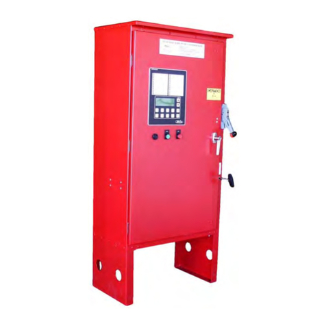
I. Cabinet - A heavy gauge steel cubicle encloses the controller. The lights, stop button, and meters are
mounted on the front of the cubicle. The control switch, battery circuit breakers, and manual start
pushbuttons are mounted behind a break-glass in the door of the cabinet.
PART III: OPERATION OF THE CONTROLLER
A. When the four (4) position control switch is in the "Auto" position and both circuit breakers are in
the "On" position, the controller is in standby condition ready to start the engine automatically. A

- 4 -
green pilot light marked "Auto" will illuminate in this position. Also, Battery No.1 and Battery
No.2 green lights will illuminate indicating that battery power is available. If both battery lights
are not on, verify that Battery 1 and Battery 2 circuit breakers are on, then press the “Battery
Reset” button.
When the water pressure drops below a level which is preset on the internal water pressure switch,
the pressure switch contacts will close, and the Controller will actuate the starter motor and the
cranking cycle will commence. If the engine starts and runs, cranking will cease and the protective
circuits will be operative. If the engine fails to start after six (6) crank periods, cranking will cease,
the "Failed to Start" light will light, and alarm bell will sound. The battery alternating circuit
alternates batteries on each crank attempt unless one battery is in a discharged state and incapable of
cranking the engine. In this instance, the control will lock onto the other battery for the remaining
cranking attempts. This non-operative battery locking circuit is reset by pushing the "Battery
Reset" pushbutton. Dry contacts for remote indication of "Battery Failure/Missing Battery" are
provided. After a “Failed to Start” failure, it is necessary to turn the control switch to
"Off" to reset.
The panel is wired so that optional remote start switches may be used, such as Deluge Valve
switches, Remote Start pushbutton, Fire Alarm switches, etc. In addition, when Option P is
provided, the Controller will automatically start the engine upon loss of Battery Charger output after
an adjustable time delay. The loss of charger light and bell are energized without delay.
While the engine is running, all protective circuits are operative. If the engine stops while running,
and there is still an auto start demand, the control will attempt to restart the engine. Failing in this,
the "Failed to Start" light will illuminate and alarm will sound. If, while the engine is operating,
the oil pressure drops below a safe limit, the “Low Oil Pressure” light will illuminate immediately.
After seven (7) seconds the alarm will sound. Should the engine temperature exceed a safe limit
while running the alarm will sound and the “High Water Temp.” light will illuminate to indicate
overheating.
In case of Overspeed, the engine will be stopped and the "Overspeed" light will illuminate and the
alarm will sound. The light and alarm will stay on until the Engine Speed Switch and the Controller
are manually reset. To manually reset the Controller, turn the Selector Switch to the "OFF"
position.
The Controller may be provided with either "Manual" or "Automatic" stop (Option R) as required.
"Manual" stop is provided as standard. A jumper must be removed between terminals 3T-1 and
3T-2 on the relay panel for an "Automatic" stop (Option R). With "Manual" stop, the engine will
continue to run even though the pressure switch or other remote starting switch returns to its normal
position. The engine can be stopped immediately only by pressing the stop button or moving the
control switch to "Off". If set up for "Automatic" stop, the engine will be stopped automatically
upon restoration to normal of whatever demand switch started the engine providing it has run at least
30 minutes, or for the period of time set on the Engine Run Timer (ERT). If the demand period was
less than the time set on the timer, the engine will continue to run until the timer times out and then
will stop.
B. When the control switch is in the "Test" position, the engine will be started by causing a drop in
water pressure. Failure circuits will be operative in the "Test" position. This method of starting
provides a test of the Controller, thereby assuring proper operation when required. The engine will
run continuously in this position until the switch is moved to "Off".
C. Placing the control switch in the "Off" position stops the engine when running, as explained in
preceding paragraphs. It also prevents the engine from starting when stopped. The switch should
always be placed in this position when servicing the engine or Controller.
D. The "Man" position of the control switch is for manually starting the engine from either battery.
The fuel and water solenoids are energized in this position, and the engine must be cranked by
pushing one of the buttons above the control switch. "Manual Crank 1" cranks from Battery 1,
and "Manual Crank 2" cranks from Battery 2. Pressing both buttons will result in cranking from
both batteries simultaneously.

- 5 -
E. Periodic Self Testing - The program clock can be set to give test runs on any day of the week and
time of day desired. A timing element is incorporated in the controls so that when the engine starts
in this manner, it will run for a definite time before it shuts down. This time is controlled by the
Program Clock, and should be set for a minimum of thirty (30) minutes.
F. A water pressure recorder with a battery operated clock drive is provided as standard. Its purpose is
to provide a permanent chart record of fluctuations of water main pressure. A record of engine starts
is shown by a sharp rise in pressure each time the engine starts. A 1/4 inch female pipe connection is
brought out the side of the cubicle for connection of the water line.
G. Provision for sequential starting (Option S) is accomplished by the use of adjustable time delay
relays installed in each controller except the lead pump. These timers are set sequentially and
progressively longer in time to prevent more than one (1) pump from starting simultaneously with
another pump. Failure of the lead pump to start will not prevent subsequent pumps from starting.
PART IV: INSTALLATION AND TEST PROCEDURE
A. INSTALLATION
The Fire Pump Controller has been assembled and wired at the factory in accordance with the
highest workmanship standards. All circuits and functions have been thoroughly tested to assure
correct operation when properly installed. The installer should be completely familiar with the
external hookup of the engine junction box to the terminal bar in the Controller. Various engine
components must be wired to the proper terminal in the controller using the correct size of stranded
wire. An appropriate size wire must be wired from the grounding lug in the controller to earth
ground. In most cases, the engine manufacturer furnishes the engines with all accessories installed
and wired to the connection box. Therefore, it is only necessary to wire from the engine connection
box to like numbered terminals in the Controller. Note proper wire sizes. All wires must be
stranded.
A drain valve is provided to relieve water pressure to the pressure switch, thus closing its contacts
and starting the engine. This test simulates an actual start demand. Since the Controller operates the
drain valve only momentarily, a small amount of water is drained off. The water pressure sensing
line to the Controller from the pump must be thoroughly flushed before connection to the Controller
in order to remove chips, particles, or other matter, which could enter the Controller.
Controllers provided with "Automatic" stop (Option R) may be changed to "Manual" stop by
connecting a jumper between 3T-1 and 3T-2. Terminals 13 and 14 have a jumper installed at the
factory. If deluge valve switches are to be used for starting, remove the jumper and wire the
normally closed contacts of the deluge start switch to terminals 13 and 14.
B. TEST PROCEDURE
All of the following tests should be made on each unit after installation. If each test is satisfactory,
the operator may place the control switch in "Auto" position and depend upon the panel operating
properly when required. Also, any one or all of these tests may be carried out at any time after
installation, if so desired.
NOTE: If 115 Volts A.C. is not connected to Controller, remove 18CR to prevent "Charger or
AC Failure" light and alarm from being energized during these tests.

- 6 -
ENGINE TERMINAL (terminals 1-12) STATUS INDICATOR LIGHTS
Light Emitting Diodes (L.E.D.) lights have been installed above each engine wiring Terminal 1
through 12, except 11, to indicate the status of each terminal. Status indicator lights above
Terminals 6 and 8 should be on at all times when both batteries are connected. No light on
Terminals 6 or 8 indicates no battery power to that terminal. Status indication is given below:
Terminal Number L.E.D.(light) "ON" Indication
1 Power available to fuel and water solenoids
2 Speed switch has operated into crank disconnect mode
3 Speed switch has operated into overspeed mode
4 Oil Pressure switch contacts closed (Low Oil Pressure)
5 Water temperature switch contacts closed (High Engine Temperature)
6 Battery #1 voltage present
7 Battery and/or alternator voltage present
8 Battery #2 voltage present
9 Crank #1 voltage present (while cranking on #1 Battery)
10 Crank #2 voltage present (while cranking on #2 Battery
12 Energize to stop voltage present
1. BATTERY LOCKOUT TEST:
a. Turn on Battery #1 switch, Battery #1 light should be on.
b. Turn on Battery #2 switch, nothing should happen.
c. Press the "Battery Reset" button. Battery #2 lights should come on.
d. Turn Battery #1 switch off for a couple of seconds and back on. Battery #1 light
should go off and remain off.
e. Press "Battery Reset" button. Battery #1 light should come on.
2. CRANKING CYCLE TEST: This test simulates a condition where the engine refuses to
start.
a. Disconnect Terminal No.1 on Controller panel. NOTE:Disconnecting Terminal
No.1 is for the purpose of removing power from the fuel solenoid so engine
will not start. On engines where the fuel solenoid is not used (Caterpillar),
or is connected other than through Terminal #1 (Clarke-G.M.), other
means must be used to stop fuel flow to the engine to prevent starting.
b. Place control switch in "Test" position to crank engine. Time the crank and rest
periods, and count the number of cranks. There should be six (6) crank periods
separated by five (5) rest periods each of approximately 15-seconds duration. The
"Failed to Start" light should come on and the alarm bell should sound. Status
indicator light #1 should come on as soon as the selector switch is moved to
"Test" and pressure switch operates. Status lights 9 and 10 should come on
alternately to indicate cranking cycle.
c. Turn Control Switch to "Off" and properly reconnect all leads.
NOTE:In order to prevent discharging the starting batteries, this same test
can be made without actually cranking the engine by disconnecting
the starter cable and observing the action of the starter contactors
and/or status indicator lights 9 and 10.
3. CHECKING STARTING MOTOR RELEASE
a. Place control switch in "Test" position. Engine should start promptly and starting
motor should release at approximately 1/3 of engine speed. Status indicator light
#2 should come on to indicate speed switch has operated to disconnect cranking.
NOTE: A convenient method of determining the exact instant the starter
releases is to connect a battery test light or voltmeter across the
starter terminals and observe when power is disconnected.
b. Return Selector Switch to "Off" to stop engine.

- 7 -
4. OIL PRESSURE FAILURE TEST:
a. Place control switch in "Test" position to start engine.
b. When the engine is starting and oil pressure is not yet up to full pressure, the
"Low Oil Pressure" light will illuminate , but the bell will not ring. When
pressure builds up, and the switch opens, the light will go out. This feature
provides indication that the oil pressure switch contacts are operating in a normal
manner.
c. After the engine is running, connect a temporary jumper between terminal #4 and
terminal #11.
d. Both the "Low Oil Pressure" light and status indicator light #4 should come on
immediately. Wait approximately seven (7) seconds. Alarm bell should sound.
e. Turn control switch to "Off" to stop engine and remove jumper between terminal
#4 and terminal #11.
f. Wait at least 30 seconds for elements to reset before making any further tests.
5. WATER TEMPERATURE FAILURE TEST:
a. Place control switch in "Test" position to start engine.
b. Jumper contacts on water temperature switch on engine.
c. Alarm bell sounds and the "High Engine Temperature" light on controller
illuminates immediately. Status indicator light #5 should come on with "High
Engine Temperature” light.
d. Turn control switch to "Off" to stop engine, and remove jumper on water switch.
6. OVERSPEED FAILURE TEST:
a. Turn the control switch to "Test" to start engine.
b. Momentarily short the contacts on the engine speed switch, or connect a
temporary jumper between terminal #3 and #7 on the controller.
c. The alarm bell sounds and the "Overspeed" light will illuminate immediately.
Engine comes to a stop. Status indicator light #3 should come on with the
"Overspeed" light.
d. Turn the control switch to "Off".
7. AUTOMATIC STARTING TESTS:
a. If the program clock is in a run position, set to a non-run condition. (See
manufacturer’s instructions.)
b. Place control in "Auto" position.
c. Bleed off pressure in system until pressure switch closes.
d. Engine should start automatically and continue to run after switch has opened if
arranged for "Manual" stop. If arranged for "Automatic" stop, engine will
continue to run for time set on Engine Run Timer and then stop.
e. Turn control switch to "Off" to stop engine.
f. Repeat tests for each demand switch such as deluge valve, remote start, etc.
8. PERIODIC STARTING TEST:
a. Pressure must be up and pressure switch open and all other demand switches de-
activated.
b. 110 V.A.C. power must be alive to panel.
c. Place control switch in "Auto" position.
i. If drain valve operates and if engine starts at once, the program clock has
tripped to the operating position, and engine will run for the remaining
time on the program clock.
ii. If engine does not start immediately, manually set the program clock to
an "On" condition. (See manufacturers instructions). The drain valve
will relieve pressure; the engine will start and then run for the time
setting of the program clock and stop.
9. ADJUST SETTING OF ENGINE RUN TIMER (OPTION R): Set the Engine Run
Timer to the desired run time. Never set the time to less than thirty (30) minutes.
10. SETTING PROGRAM CLOCK: See manufacturer’s instructions at the end of this
manual for setting the program clock.

- 8 -
11. REMOTE START SWITCH CIRCUITS: Field wiring terminals are provided on the
controller so that optional remote start switches such as Remote Pushbutton Stations,
Deluge Valve Switch, the Fire Alarm Switch, etc., may be used to start the engine. Two (2)
sets of terminals are provided. Terminals #15 and #16 are used for remote manual start
pushbuttons (close to start). Terminals #13 and #14 are used for remote Deluge Valve
Switch or other remote automatic start switches (open to start). Upon automatic start from
this type of switch, the engine will be stopped either automatically after the demand switch
de-activates and Engine Run Timer times out, or manually at the Controller. Terminals #13
and #14 must have a jumper installed if a remote Deluge switch is not to be used. When the
controller is shipped from the factory terminals #13 and #14 will have a jumper installed.
12. POWER FAILURE STARTING (OPTION P): To test this optional feature, disconnect
normal 120 V.A.C. to the Controller. After the set time delay (2TR), the Controller will
commence cranking the engine. The "Charger or AC Failure" lamp will illuminate and
alarm will sound without delay.
13. NORMAL OPERATION – AUTOMATIC: Place control switch in "Auto" position.
Green "Auto" light will illuminate and engine will automatically start upon drop in
pressure or operation of other start switches. If provided with "Manual" stop feature the
engine must be turned off at the Controller. The engine will also start periodically from the
Program Clock and run for length of time set on the Program Clock, then stop. On
"Automatic" stop Controllers, upon termination of the demand signal, the engine will run
for the length of time left on the Engine Run Timer and then will stop automatically.
14. ADJUST SEQUENTIAL START TIMERS WHEN OPTION S IS SUPPLIED FOR
MULTIPLE PUMP INSTALLATION: Normally, the leading pump Controller will not
have a delay timer and will commence cranking the engine immediately upon operation of a
demand signal (other than Power Failure which is time delayed). The subsequent
Controllers will have a solid state time delay relay (3TR) which is adjustable from 0 to 100
seconds. Each delay relay should be set with progressively longer times on each
subsequent pump. The recommended time interval is ten (10) to fifteen (15) seconds;
however, this may be extended or shortened as required by the local authorities having
jurisdiction. If the length of adjustment time required is other than 0 to 100 seconds, a
suitable timer can be supplied.
16. LOW FUEL SUPPLY (OPTION F): Field terminals have been provided for low fuel
level contacts. The Controller is arranged so the alarm will sound and the “Low Fuel” light
will illuminate when the low fuel contacts close. The alarm cannot be silenced until fuel
is added to the fuel tank.
17. PUMP ROOM ALARMS (OPTION K): Field terminals may be provided for various
inputs from pump room alarms. These alarms include: Low Fuel, Low Pump Room
Temperature, Reservoir Low, Reservoir Empty, Low Suction Pressure, Relief Valve
Discharge and/or Flow Meter On. The Controller is arranged so that the alarm will sound,
and the light will come on when alarm sensor contacts close. These pump room alarms can
be silenced with a push button mounted on the Controller.
PART V: TROUBLE SHOOTING HINTS
This Controller has been carefully engineered and built to give years of dependable, trouble-free service. However, for
various reasons difficulty may be encountered in the operation. Therefore, the following information is submitted as a
guide for locating troubles that are easily corrected. If the trouble proves to be beyond the scope of this manual, consult
the factory before proceeding further. NOTE:Check to see that all relays are firmly seated in their sockets. Also
verify that status light numbers 6, 7, and 8 are on.
A. ENGINE REFUSES TO CRANK
1. Check status lights 9 and 10 to see if controller is applying power to crank terminals. If
lights operate, problem is in the engine, or engine to controller wiring. If not, proceed to B.

- 9 -
2. Check to see if status light #2 is on. If #2 is "hot", the crank termination speed switch is
closed. Check or replace speed switch.
3. If there is no voltage at Terminal No.2 and engine still does not crank, the crank relay
(7CR), engine running relay (9CR), or auto start relay (8CR) may be defective. Replace.
4. Check batteries to be sure they are fully charged. VOLTAGE MEASUREMENT
WITHOUT AN ACTUAL CRANKING LOAD IS NOT A SUFFICIENT CHECK
FOR BATTERY CONDITION.
5. Check all battery and ground connections from battery to junction box to panel. Check
battery circuit breakers to be certain they are turned on. Also, check starting motor cables
and contactor connections.
B. ENGINE CRANKS BUT DOES NOT START
1. Check to see that status light #1 is on (Terminal #1 is "hot"). If not, Fuel Solenoid Relay
(6CR) may be defective. Replace. On “Energize to stop” type engines, check to see that
status light #12 is "Off".
2. Check fuel solenoid.
3. When engine does not start, cranking time is limited as previously described. If cranking
does not stop and “Failed to Start” signal does not come on, check Solid State Crank
Control portion of the main logic board.
C. ENGINE STARTS BUT STARTER DOES NOT RELEASE
1. Check status light #2. The #2 status light should be off indicating no voltage while the
engine is cranking and should come on before the engine reaches 1/2 of normal speed. The
speed switch used for starter disconnect should close it's contacts at about 1/3 engine speed
to put battery voltage into Field Wiring Terminal Bar (1T) Terminal No.2. If not, replace
switch.
2. If the above test indicates voltage on 1T Terminal No.2 is satisfactory, engine running relay
(9CR) may be defective. Replace.
3. If starter does not release, check the contacts on the starter to make sure they are not welded
together.
D. ENGINE WILL NOT START ON WEEKLY TEST RUNS
NOTE: On these test runs, the engine starts from the program clock. See manufacturer's
instructions for setting and operating program clock.
1. Make sure clock is set for the day the engine is to start.
2. Operate the program clock to the manual position so that it trips to the "On" position and
the drain valve operates (See manufacturer’s instructions). If drain valve does not
operate, the Program Clock, Relays 4CR, 6CR, or diode D50 on the main logic board could
be defective. If drain valve operates but the engine does not start, check to see if pressure
switch trips. Also, check the auto start relay 8CR.
E. ENGINE WILL NOT STOP ON TEST RUNS OR STARTS EVERY TIME CONTROL
SWITCH IS PLACED IN "AUTO" POSITION.
1. Stop engine by turning control switch to "Off".
2. Check pressure switch making certain that its contacts are open and that all other demand
switches are de-activated.
3. Be sure Program Clock is not tripped "ON".
4. If Solenoid Drain Valve opens each time the switch is placed in "Auto" Program Clock
may be defective.
5. If any remote start switches are wired to terminals #13/#14 or #15/#16 make sure the
position of the remote start switches is correct. If no remote start switches are connected to
terminals #13 and #14 check to see if there is a jumper installed between the terminals.
F. LOW OIL PRESSURE ALARM DOES NOT OPERATE
1. Selector switch must be in "Auto" for this test. Simulate "Low Oil Pressure" by
shorting the Oil Pressure switch. "Low Oil Pressure" light should come on immediately.
Wait approximately seven (7) seconds for time delay to operate alarm. If oil light does not
illuminate, but status light #4 comes on, the problem is in the Controller. If status light #4
does not come on, the problem is in the engine or engine to Controller wiring.

- 10 -
2. Check wire from control panel to oil pressure switch on engine and also from switch to
ground on two-wire switches.
G. HIGH ENGINE TEMPERATURE ALARM DOES NOT OPERATE
1. Selector switch must be in "Auto" and the engine running for this test. Simulate high
water temperature by shorting terminals of temperature switch. If "High Engine
Temperature" light and/or alarm does not come on and status light #5 does not come on,
the problem is in the engine or engine to Controller wiring.
2. Check wire from panel to water temperature switch and also from switch to ground on
two-wire switches.
3. If operation is correct on this test but not under actual high engine temperature conditions,
replace water switch.
H. OVERSPEED ALARM AND SHUTDOWN DOES NOT OPERATE
1. Simulate Overspeed by momentarily shorting terminals of the speed switch. If status light
#3 is on but engine does not shutdown and alarm does not operate, problem is in Controller.
If status light #3 does not come on, problem is in engine or engine to Controller wiring.
2. Check wire from panel to Overspeed switch.
3. If engine stops, and the light and alarm operate on this test, but not under actual conditions
by overspeeding engine, replace overspeed switch.
4. If Controller is at fault, check relay 15CR, diode D46, D47, or D49 on the main logic board.
I. CIRCUIT BREAKER IN CONTROLLER TRIPPED
1. Check to see if Voltage Regulator is sticking.
2. Check to see if engine generator or alternator is charging above the capacity of the breaker -
20 amperes. Note: On newer engines the charging circuit does not go through the
controller.
3. Check for external short circuits to ground in all wires from panel.
4. Check conditions of status lights. See - TEST PROCEDURE.
J. LOSS OF BATTERY CHARGER OUTPUT
1. Check A.C. voltage to charger.
2. Check charger fuses.
3. Check connections to charger.
4. See separate NRG charger manual for troubleshooting procedures.
PART VI: SEQUENCE OF OPERATION
A. Introduction
Refer to schematic wiring diagram. All relay contacts are shown in the de-energized position.
Control relays are designated as CR. Diodes designated D are located on the main logic board;
diodes designated PD are stud mounted on the relay panel; and Time delay relays are designated TR.
Squares with numbers designate field wiring terminals and diamonds with letters designate terminals
for connections within the Controller. The main logic board designated LB contains circuits for the
Crank Control (CC), Voltage Sensing Circuit (VS), Alternating Relay (AR), Oil Pressure Solid State
Timer (K1), Field terminal LEDs and all the diodes except the power diodes 1PD and 2PD.
Connections to the main logic board a designated with hexagons.
B. Controller Battery Power
Power to operate Controller comes from the two engine batteries. Battery No.1 is connected to Field
Wiring Terminal Bar (1T) Terminal 6 and is fed through Circuit Breaker 1CB to Diode 1PD, the LB
pin 36), the Manual Crank Pushbutton (1PB), and the Battery Switching Relay (5CR terminal 1).
Battery No.2 is connected to 1T Terminal 8 and is fed through 2CB to 2PD, LB pin 37, the Manual
Crank 2 Pushbutton (2PB) and 5CR terminal 4. Diodes 1PD and 2PD allow the Controller to receive
battery power from the battery with the higher potential.
Relays 10CR and 11CR are battery failure relays, and are energized through the solid state Voltage
Sensing (VS) Circuit portion of the main logic board. If both batteries are fully charged, 10CR and
11CR are held energized through the VS and both battery lamps 1B and 2B will be lighted. The

- 11 -
voltage sensing circuit allows the battery failure relay to drop out when the battery potential drops
below a level of about 60 percent of nominal for a period of several seconds. If a low battery voltage
is sensed, the appropriate battery failure relay will drop out and lock the other one in.
If Battery No.1 goes low or fails, 10CR will drop out. Its Normally Closed (N.C.) contacts
(terminals 1 and 7) close and keep 11CR energized independent of the VS circuit. These contacts
also lock the battery switching relay 5CR in the energized position by way of the Alternating (AR)
on the main logic board. With 5CR held energized, its Normally Open (N.O.) contacts (terminals
4,7,6, and 9) will be held closed so that cranking power can be provided only by Battery No.2
through 7CR contacts to 1T Terminal 10. 10CR N.C. contacts (terminals 1 and 7) energize the
Alarm Relay 13CR through diode D24 to sound the alarm. If Battery No.2 fails, 11CR drops out and
locks in 10CR through 11CR N.C. contacts (terminals 1 and 7). 10CR N.C. contacts (terminals 1 and
7) open and 11CR contacts (terminals 5 and 8) stay open and keep 5CR from energizing. The N.C.
contacts (terminals 1,3,7, and 9) of 5CR remain closed so that cranking power can be provided only
by Battery No.1 through 7CR contacts to 1T Terminal 9. 11CR N.C. contacts (terminals 1 and 7)
energize the alarm relay 13CR through diode D29 and sounds the alarm.
When the two batteries are turned on, the first one on will energize its battery failure relay and lock
out the other one. Pressing the "Battery Reset" pushbutton, 3PB, will pull in the second battery
failure relay if the battery voltage is high enough. Any time a battery failure is sensed and one of the
corresponding relays drops out, the "Battery Reset" pushbutton must be pressed to reset the circuit.
Diodes D68 and D23 on the main logic board are used to isolate the VS circuit from the alarm
circuit.
C. Automatic Operation: For automatic operation, the selector switch is in the "Auto" position. The
Controller is then in a standby mode, and all automatic functions are ready for operation. The
"Auto" light and both battery lights should be on. The Controller will start from any of the following
demand signals:
1. Closing of pressure switch contacts due to a drop in water pressure.
2. Remote start switches.
3. Deluge switch.
5. Power Failure Start (Option P).
All automatic starting is accomplished through the auto start relay 8CR. In sequential start
controllers, auto starts from the pressure switch and deluge switch are delayed by the Sequential Start
Timer (3TR).
D. Drop in Water Pressure: On a drop in water pressure, the pressure switch contacts close, applying
power to the coil of auto start relay 8CR. In sequential start controllers, the pressure switch contacts
apply power to the coil of the Sequential Start Time delay relay (3TR), and the contacts of 3TR
operate the coil of 8CR after the time delay set on 3TR. 8CR locks in through its own N.O. contacts
(terminals 6 and 9). 8CR is locked in and remains energized even after the pressure switch contacts
open until either the "Stop" pushbutton (4PB) contacts are opened, the ERT contacts open, or the
selector switch is turned to "Off". If the pressure switch contacts remain closed, turning the selector
switch to "Off" is the only means to de-energize 8CR and stop the engine.
With 8CR energized, its N.O. contacts (terminals 7 and 4) close to apply power to the Fuel Solenoid
relay 6CR, to the Crank Control (CC) circuit through 9CR N.C. contacts (terminals 1 and 7), and to
the Crank relay 7CR. At this time the CC unit starts timing the first crank period. 7CR energizes
closing its N.O. contacts (terminals 7 and 4) to apply battery power through 5CR N.C. or N.O.
contacts (terminals 3 and 9 or terminals 6 and 9) to 1T Terminals 9 or 10 depending on whether or
not 5CR is energized. Battery power on Terminals 9 or 10 energizes the engine starting contactor,
and, thus, cranking of the engine starts as soon as the pressure switch closes.
After a period of approximately 15 seconds, if the engine has not started, the Crank Control circuit
energizes 1CR. When 1CR energizes, its N.C. contacts (terminals 3 and 9) open and 7CR
de-energizes, thus stopping the crank cycle. N.C. contacts of 7CR (terminals 2 and 8) energizes the
Alternating Relay (AR) circuit which in turn energizes and de-energizes 5CR alternately each crank
cycle. 5CR contacts transfer to switch to Battery 2 (Battery 1) power and to 1T Terminal 10 (1T
Terminal 9). After approximately 15 seconds rest, 1CR de-energizes and 7CR energizes, thus

- 12 -
completing the circuit from the other Battery to 1T Terminal 9 or 10. The engine now cranks on the
alternate battery power. If the engine fails to start, this cycle repeats for a total of six (6) crank
periods alternating batteries each time.
After six (6) crank periods the "Failed to Start" relay 3CR is energized. Its N.O. contacts
(terminals 6 and 9) close to energize the alarm relay 13CR through diode D30. Relay 3CR N.C.
contacts (terminals 1 and 7) open to stop the cranking and another set of N.C. contacts (terminals 3
and 9) opens to drop out the Fuel Solenoid relay 6CR. A set of 3CR N.O. contacts (terminals 7 and
4) closes to light the "Failed to Start" light.
If the engine starts, the engine speed switch applies battery voltage to 1T Terminal 2 and energizes
Engine Running relay 9CR. 9CR N.C. contacts (terminals 1 and 7) open and cut off power to the
cranking circuits. 9CR contacts connected to 1T Terminals 20, 21, 22, 23, 24, and 25 are used for
remote indications of engine running.
The engine "Low Oil Pressure" light is powered only when the Controller is in the run mode and
6CR contacts (terminals 9 and 6) are closed or when the selector switch is in the "Man" position.
This prevents the "Low Oil Pressure" light from coming on when the Controller is in "Auto" and
in the standby mode with the engine not running. It also allows the light to come on when the engine
is cranking, while the oil pressure switch is still closed, thus, giving an indication that the oil pressure
switch is working. When the engine starts, battery power is applied to one side of the Oil Pressure
Alarm Delay Timer circuit on the main logic board. If the oil pressure is low, the oil pressure switch
is closed and completes the circuit through 1T Terminal 4 and D45 to K1. If the oil pressure remains
low the oil pressure timer will time out and relay contacts of K1will close and energize the alarm
relay 13CR through D27. The "Low Oil Pressure" light will remain on as long as the oil pressure
switch is closed. Normally, the oil pressure comes up as soon as the engine starts, so the oil pressure
timer does not remain energized long enough to time out.
The water temperature switch is N.O., and closes on high engine water temperature. When it closes
it operates the water temperature light on the Controller through 1T Terminal 5 and energizes the
alarm relay through D31.
If an overspeed condition should develop while the engine is running, a speed switch on the engine
closes and puts battery voltage on 1T Terminal 3. This energizes the Overspeed relay 15CR through
diode D47. 15CR locks in on its own N.O. contacts (terminals 4 and 7) through diode D46, and,
thus, remains energized until reset by switching the Controller to "Off". 15CR N.O. contacts
(terminals 6 and 9) close to turn on the "Overspeed" light and energize 13CR through diode D28.
15CR N.C. contacts (terminals 3 and 9) open to de-energize the auto start relay and disable the
cranking circuits and shutdown the engine.
If the Controller is wired for "Automatic Stop" and the water pressure has returned to normal, 8CR
will drop out after the ERT times out and its contacts open. The ERT timer starts timing when 8CR
is energized by the closure of N.O. contacts (terminals 5 and 8) to the ERT Coil. If the Controller is
wired for "Manual Stop", 8CR will remain locked in until the control switch is turned to "Off" or
the "Stop" pushbutton is pressed. The ERT is installed to assure that the engine runs for a minimum
time, and should be set to at least 30 minutes. If the pressure switch remains closed for a longer
period than set on the ERT, the ERT will time out but 8CR will remain energized through the
pressure switch until the pressure switch contacts open.
The alarm circuit consists of a bell mounted on the outside of the enclosure, and is controlled by
13CR N.O. contacts (terminals 6 and 9). 13CR is energized by one of the following failures:
1. Engine Overspeed
2. Low Oil Pressure
3. High Water Temperature
4. Loss of Battery Charger Output
5. A Battery is Missing/Disconnected
6. Failed to Start
7. Battery Failure
8. Low Fuel Level (Option F)
9. Pump Room Alarm (Option K)

- 13 -
The diodes in the alarm circuit are used to isolate the various alarm contacts so that Alarm relay
13CR may be used for more than one function.
E. REMOTE START: The remote start switch or switches are N.O. which close momentarily.
Depressing a remote start switch energizes 8CR which is then locked in through its N.O. contacts
(terminals 6 and 9).
F. DELUGE SWITCH: The deluge switch or switches are N.C. switches, and keep the Deluge relay
14CR energized. Opening a deluge switch contact de-energizes 14CR to allow its N.C. contacts
(terminals 1 and 7) to close and energize 8CR. The remaining sequence of operation is the same as
for a start from water pressure drop described above.
G. POWER FAILURE START (OPTION P): This option automatically starts the engine after a time
delay upon loss of battery charger output. Relay 18CR is held energized by an alarm output of the
battery charger. If the battery charger output should fail, 18CR will drop out and its N.C. contacts
(terminals 1 and 7) will energize 2TR. When 2TR times out its N.O. contacts (terminals 1 and 3)
will close and energize 8CR. The remaining sequence of operation is the same as for a start from
water pressure drop described above.
H. WEEKLY TEST START: The weekly test is initiated by a 7-day Program Clock (PC) operated
from the A.C. line. At the time and day of week programmed, its N.O. contacts close and energize a
Solenoid Drain Valve (SDV) through 6CR and 4CR. The SDV is a three way valve and is connected
in the sensing line to the pressure switch. When it is energized it closes the connection between the
pressure switch and the sensing line and then vents the pressure switch to atmosphere causing the
pressure switch to operate. This, in turn, causes an automatic start as described above. When the
Fuel Solenoid relay 6CR energizes its N.C. contacts (terminals 1 and 7) open and de-energize the
SDV. These contacts also keep the SDV from energizing while the engine is running. The SDV is
open just long enough to drop the pressure and initiate the start sequence.
When the crank relay 7CR energizes, its N.O. contacts (terminals 6 and 9) close to energize 4CR, the
weekly test relay, which locks in on its own N.O. contacts (terminals 4 and 7). 4CR N.C. contacts
(terminal 3 and 9) open to keep 8CR from locking in on those controllers wired for manual stop.
8CR is held energized by the P.C. contacts through diode D51 for the duration of time set on the P.C.
The purpose of the diode D51 is to isolate 4CR contacts from the SDV. When the P.C. contacts
open 4CR drops out, and if all starting causes are normal, 8CR also drops out and the engine stops.
I. Test Start: Switching the controller selector switch to the "Test" position initiates an automatic start
by energizing the solenoid drain valve (SDV) as described above to drop the water pressure to the
pressure switch. The starting sequence is the same as described above. The engine will continue to
run until the selector switch is switched to "Off".
J. Manual Start: The "Man" position of the controller disconnects all automatic start circuits of the
controller and permits manual starting of the engine on either one or both batteries by pressing the
appropriate crank pushbutton(s). All alarms are functional in the "Man" position. The engine will
continue to run until the selector switch is turned to "Off".
K. Additional Features
1. Engine Lockout (Option E): Relay 19CR is an Engine Lockout relay which, when
energized, will keep the engine from starting, or will stop the engine if it is running. This
feature may be used to lock out one pump in a two-pump system, when the other is running,
or to lock out the pump in case of low suction pressure when this is a requirement. The
engine lockout can be overridden by placing the selector switch in "Man" and pressing the
"Manual Crank"buttons.
2. Energize to Stop: This is provided for engines that have a normally open fuel solenoid that
must be closed in order to stop the engine, i.e. Caterpillar engines. With this circuit 1T
Terminal 12 is hot (battery power applied) at all times except while the engine is running.

- 14 -
3. Remote Alarm Contacts: 1T Terminals 17, 18, and 19 provide contacts for a remote
indication that the switch is not in "Auto" position. 1T Terminals 20, 21, 22, and 23, 24,
25 provide two (2) sets of Engine Running contacts. One set can be used for remote alarm
indications, and the other for any other required control function. 1T Terminals 26, 27 and
28 provide a set of contacts for a remote indication of a system failure. 1T Terminals 29, 30
and 31 provide a set of contacts for remote indication of the failure of either battery. 1T
Terminals 34 through 41 are used to provide an alarm signal in case of low fuel level
(Option F), or any other pump room alarm conditions (Option K). These alarm functions
require N.O. contacts that close to represent an alarm condition. 1T terminal 34 is a
common terminal for all alarm sensor contacts. 1T Terminals 35 through 41 connects to
one side of the pump room alarm sensor contacts. Relay 20CR is an Alarm Silence relay
energized by "Alarm Silence" pushbutton 5PB. 20CR is held energized by its own N.O.
contacts (terminals 6 and 9) as long as the alarm condition is present. When the alarm
condition is cleared 20CR N.C. contacts (terminals 1 and 7) open and let 13CR drop out.
4. Individual Alarm Contacts (Option A): Contacts for individual indication of each alarm
condition along with customers specified alarms may be provided by Relays 51CR through
60CR and one pole of 15CR and 18CR. These contacts are wired to 1T Terminals 51
through 86.
5. Battery Charger Operation (Option J): The Battery Chargers are mounted in the engine
controller, and are factory wired to the controller terminal block from which they obtain the
120 volt AC supply voltage, and through which they provide charging current to the
batteries. The charging current to the two (2) batteries is monitored by means of two (2)
ammeters mounted in the controller light panel. Voltmeters are also provided to monitor
the two (2) battery voltages.
The battery charger is line voltage regulated, and will operate over a voltage range of 94
volts to 132 volts at 60 Hz (or 50Hz for a 50Hz controller). The charger output is current
limited and provides full protection during the engine cranking cycle.
The battery charger will not function if a battery is not connected to the controller. The
battery fault light on the charger will be illuminated and the charger failure lamp on the
controller and the audible alarm will be on. In addition if a battery is missing the
appropriate battery light will go out and an alarm will sound.
IMPORTANT!
PART VII: BATTERIES/BATTERY CHARGER
A. Inspect For:
1. Engine starting batteries have been inspected for proper: electrolyte (acid) level, location
(battery rack), ventilation, adequate cable size, and correct electrical/mechanical
connections to engine and controller.
2. Integral battery charger has been connected to proper A.C. supply voltage. It is preferable
that an external circuit breaker/disconnect means rated at least twenty (20) amps be utilized
for A.C. supply voltage.
3. The integral battery charger is designed to meet the requirements of NFPA-20, and bring a
"good" battery (discharged only) back to a full charge within a continuous 24 hour period
under normal conditions.
Upon energizing the integral battery charger, the panel mounted controller ammeters will indicate a
high rate of charge (10-15 amps/meter). Voltmeters should indicate proper voltage 12/24 volts D.C.
depending on system voltage.
Generally, when all conditions are normal, the batteries will come to a full charge prior to the 24
hour period. As batteries begin to charge, the controller ammeters will indicate a gradual decrease in
current flow.

- 15 -
Check batteries daily for a few days after initial installation has been made, and weekly thereafter.
Batteries should be checked for overcharging (gassing), or undercharging (low voltage, or low
specific gravity of the electrolyte or acid).
CAUTION: Under no circumstances should new electrolyte (acid) be added to a battery that
has been previously filled. Only water designated battery water (distilled) is
recommended for maintenance purposes.
B. BATTERY CHARGER FIELD OPERATION: Please see the separate Installation and
Operation Manual for the Battery Charger for specific operation and troubleshooting
instructions
Table of contents
Other METRON Controllers manuals
Popular Controllers manuals by other brands
Controlli
Controlli MVE2 R Series Mounting instructions
ABB
ABB IRC5 Compact product manual
LAE electronic
LAE electronic SSD90B Series Instructions for installation and use

Nibe
Nibe Climacool CoolLogic UCA/W quick start guide
Geco
Geco GC202 Installation, operating and maintenance manual

Mitsubishi Electric
Mitsubishi Electric A173UHCPU Programming manual
