Metropolitan Industries Sump Boss BP2000 Supplement

Sump Boss
Metropolitan Industries, Inc.
www.metropolitanind.com
OPERATION MANUAL
Dated: 9/17/09
Supersedes: None
Document No.: SBossO&M Page 1 of 19
Register your product at
www.sumpro.com
SUMP BOSS
MODEL BP2000
BATTERY-OPERATED
SUMP PUMP WITH
THE “SMART CHARGER”
ELECTRONIC CONTROLLER
INSTALLATION &
SERVICE MANUAL

Sump Boss
Metropolitan Industries, Inc.
www.metropolitanind.com
OPERATION MANUAL
Dated: 9/17/09
Supersedes: None
Document No.: SBossO&M Page 2 of 19
Register your product at
www.sumpro.com
SUMP BOSS
THE NEW STANDARD IN BATTERY
OPERATED PUMPS & CONTROLS
INTRODUCTION
The SUMP BOSS is a battery operated
sump pump that can be used as either
a primary or standby pump. In the
event of a power outage the pump will
switch to the battery as a power source.
When 115v power is again available the
“Smart Charger” will return to line power
automatically.
IMPORTANT SAFETY INSTRUCTIONS
READANDSAVETHESEINSTRUCTIONS
– THIS MANUAL CONTAINS
IMPORTANT SAFETY AND OPERATING
INSTRUCTIONS FOR MODEL BP 2000
BATTERY CHARGER.
!!!WARNING!!!
!!!WARNING!!!
!!!WARNING!!!
BEFORE USING BATTERY CHARGER
READ ALL INSTRUCTIONS AND
CAUTIONARY MARKINGS ON BATTERY
CHARGER, BATTERY AND SUMP BOSS.
FAILURE TO HEED SAFETY
INSTRUCTIONS AND WARNINGS
COULD RESULT IN INJURY OR DAMAGE.
Always disconnect batteries and discon-
nect SUMP BOSS from the AC power
source before storing, handling or making
any adjustments to the unit.
Use SUMP BOSS only as described in this
manual. Any other use not recommended
by the manufacturer may cause re, elec-
tric shock or injury to persons.
Do not sit or stand on SUMP BOSS.
Keep children away.
Do not place objects on SUMP BOSS or
allow vents to become blocked.
The SUMP BOSS is designed to only
handle clear water. DO NOT use in septic
tanks to pump efuent or sewage pits to
pump sewage.
Do not smoke, use sparkable electrical de-
vices or open ame when working on this
unit.
Do not install SUMP BOSS in locations
classied as hazardous per N.E.C., ANSI/
NFPA 70-1984.
ELECTRICAL SHOCK HAZARD
This unit has not been evaluated for use
outdoors – Never operate SUMP BOSS
outdoors.
Never operate SUMP BOSS with battery
enclosure open.
Never operate SUMP BOSS in a wet loca-
tion.
Never operate SUMP BOSS in a location
where liquid or moisture will come in con-
tact with, splash on or drip on unit.

Sump Boss
Metropolitan Industries, Inc.
www.metropolitanind.com
OPERATION MANUAL
Dated: 9/17/09
Supersedes: None
Document No.: SBossO&M Page 3 of 19
Register your product at
www.sumpro.com
!!!WARNING!!!
!!!WARNING!!!
!!!WARNING!!!
RISK OF ELECTRICAL SHOCK
RISK OF ELECTRICAL SHOCK
In the event of a short circuit, grounding
reduces the risk of shock by providing an
escape wire for the electrical current. The
SUMP BOSS must be properly grounded.
The SUMP BOSS is equipped with a
cord having a grounding wire with an
appropriate grounding plug. The plug
must be used with an outlet that has been
installed and grounded in accordance
with all local codes and ordinances. The
outlet must be the same conguration as
the plug. Where a two-prong wall outlet is
encountered, it must be replaced; contact
a qualied electrician. To reduce the risk
of electrical shock, the grounding plug
blade must not be cut off at the plug. Do
not use the three-prong plug with a two
prong adapter. Do not attempt to defeat
this safety feature.
Use the SUMP BOSS only with adequate
wiring that is up to code.
Connect to properly grounded outlets only.
The SUMP BOSS is capable of and in-
tended to generate electrical current when
unplugged from the wall outlet or when the
AC power is shut off.
Because the SUMP BOSS uses batter-
ies, both the battery and the power cord
must be disconnected to neutralize the
SUMP BOSS. Failure to disconnect both
the battery and the power cord will result
in electrical shock sufcient to cause injury
or death.
BATTERY PRECAUTIONS
IMPORTANT SAFETY INSTRUCTIONS.
SAVE THESE INSTRUCTIONS
A. Servicing of batteries should be
performed or supervised by personnel
knowledgeable of batteries and the
required precautions. Keep unauthorized
personnel away from batteries.
B. When replacing batteries, use
only models conforming to Battery
Council International (BCI) 27 DC
specications for GROUP 27 DEEP
CYCLE MARINE BATTERIES. Other
types of batteries may burst causing
personal injury and damage.
• Die Hard Model 27524
• Exide Model NC-27
• Interstate Model SRM-27
• Metropolitan Model 27t-36
• NAPA Model 8270
Do not insert or allow foreign objects to
enter any ventilation or exhaust openings
as this may cause electrical shock and/or
a re hazard.

Sump Boss
Metropolitan Industries, Inc.
www.metropolitanind.com
OPERATION MANUAL
Dated: 9/17/09
Supersedes: None
Document No.: SBossO&M Page 4 of 19
Register your product at
www.sumpro.com
E. CAUTION – A battery can present a
risk of electrical shock and high short circuit
current. The following precautions should
be observed when working with batteries:
1. Remove watches, rings or other metal
objects.
2. Use tools with insulated handles.
3. Do not lay tools or metal objects on top
of batteries.
4. Wear safety goggles and a face shield.
4. Spilled electrolyte should be washed
down with a suitable acid neutralizing
agent. A common practice is to use a
solution of approximately one pound
(500 grams) bicarbonate of soda to
approximately one gallon (4 liters) of
water. The bicarbonate of soda solu-
tion can be added until the evidence
of reaction (foaming) has ceased. The
resulting liquid should be ushed with
water and the area dried.
G. CAUTION – Lead acid batteries can
present a risk of re because they generate
oxygen and hydrogen gas. The following
procedures should be followed:
1. Do not smoke near batteries.
2. Do not cause ame or spark in battery
area.
3. Discharge static electricity from body
before touching batteries by rst
touching a grounded metal surface.
H. See Battery Manufacturers’
installation manual for additional installation
maintenance and safety instructions.
F. CAUTION – The electrolyte is a
dilute sulfuric acid that is harmful to the
skin and eyes. It is electrically conductive
and corrosive. The following procedures
should be observed:
1. Wear full eye protection and clothing.
2. If electrolyte contacts the skin, wash it
off immediately.
3. If electrolyte contacts the eyes, ush
thoroughly and immediately with water.
Seek medical attention.
C. CAUTION – Do not dispose of batteries in
a re. The batteries may explode.
D. CAUTION – Do not open or mutilate
the batteries. Released electrolyte is
harmful to the skin and eyes. It may
be toxic.

Sump Boss
Metropolitan Industries, Inc.
www.metropolitanind.com
OPERATION MANUAL
Dated: 9/17/09
Supersedes: None
Document No.: SBossO&M Page 5 of 19
Register your product at
www.sumpro.com
CARTON CONTENTS Figure A.
Your SUMP BOSS system is packaged
in two separate cartons. The rst is a tall
carton labeled, “Battery Operated Pump”.
Inside this carton you will nd the pump,
complete with the oat rod and ball for the
primary switch. In a smaller box inside the
tall carton you will nd the auxiliary alarm/
pump switch.
The second is a short carton labeled
“Smart Charger”. This will contain the
electronics unit which is attached to the
battery enclosure.
Verify that all the components are included
and that they do not appear to be damaged.
Remember you will also be required
to supply a deep cycle marine battery
described earlier in these instructions
to complete the installation and proper
operation of the SUMP BOSS.

Sump Boss
Metropolitan Industries, Inc.
www.metropolitanind.com
OPERATION MANUAL
Dated: 9/17/09
Supersedes: None
Document No.: SBossO&M Page 6 of 19
Register your product at
www.sumpro.com
INSTALLATION INSTRUCTIONS
Proper Pump Placement. Figure B.
1. Remove the cover from your sump pit
if it has one. (The cover will have to be
modied after the installation is com-
plete.)
2. CAUTION: Make sure that the motor
remains dry at all times. It is not meant to
get wet or be submersed in water.
3. Remove all debris from the sump pit.
4. Set the pump in the pit making sure that
it is on a at surface. (A brick or similar
material can be used if necessary.)
5. Make sure that there is no interference
between the SUMP BOSS switch and
any objects in the basin or with the
basin itself.
Sump Boss
Metropolitan Industries, Inc.
www.metropolitanind.com
OPERATION MANUAL
Dated: 9/17/09
Supersedes: None
Document No.: SBossO&M Page 7 of 19
Register your product at
www.sumpro.com
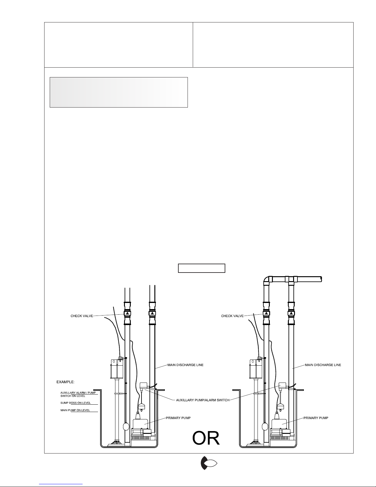
DISCHARGE PIPING AND
AUXILIARY PUMP/ALARM
FLOAT INSTALLATION
1. Discharge piping is to be installed per
FIGURE C. Always make sure that an
individual check valve is used for each
pump to avoid re-circulation (which
could cause ooding) during pumping.
Once the pump and piping are in place,
mount the auxiliary oat on the discharge
pipe.
1. Undo the hose clamp on the switch
bracket and put it around the discharge
pipe. Tighten it only to a loose t, at
this time.
2. Adjust the auxiliary oat height so that
the oat will not turn on this switch until
the water level has surpassed the on
level of the main SUMP BOSS oat
switch, which can be adjusted by sliding
the lower rubber stop up or down on
the oat rod. This switch in turn should
be adjusted to turn on at a higher level
than your primary pump switch. See
FIGURE D for an example.
3. Once you have your auxiliary switch set
at the desired height position so that
nothing in the basin will interfere with
its operation, tighten up the mounting
clamp.
CAUTION: Do not let the ends of the
power cords with this unit get wet
or submersed in the water during
installation.
METHOD:1 METHOD:2
FIGURE C

Sump Boss
Metropolitan Industries, Inc.
www.metropolitanind.com
OPERATION MANUAL
Dated: 9/17/09
Supersedes: None
Document No.: SBossO&M Page 8 of 19
Register your product at
www.sumpro.com
ADJUSTING FLOAT LEVELS: EXAMPLE
FIGURE D
Batteries & Carbon Monoxide
(CO) Detectors
All lead-acid batteries used by any back
up pump system regardless of brand emit
gases when charging. The emission of
these gases can possibly produce an odd
sulphur-like smell or sometimes will cause
a nearby CO detector to needlessly sound
an alarm. To prevent activation of CO
detectors, move the battery as far from the
detector as possible or provide a means
for the gases to escape outdoors.
Read the instructions that came with your
detector. This situation may be covered in
the literature. Always follow the advice of
the detector instructions rst.
If the CO detector alarm sounds, do not
assume that it is caused by the back-
up pump’s battery! You may have a
real presence of CO! Take all steps
necessary to insure personal safety.
After you are certain there is no CO present,
(CO can be produced by a furnace, water
heater or similar devices that use natural
gas and/or produce combustion) then
probably a battery being charged has
produced the gases responsible. The
manufacturer of the detector may be able
to supply instructions to solve this problem.

Sump Boss
Metropolitan Industries, Inc.
www.metropolitanind.com
OPERATION MANUAL
Dated: 9/17/09
Supersedes: None
Document No.: SBossO&M Page 9 of 19
Register your product at
www.sumpro.com
“SMART CHARGER” PLACEMENT
AND WIRING. Figures E & F
NOTE: If the polarity of the terminals
does not match the above description,
double check to make sure that you are
using the proper type of deep cycle ma-
rine battery required for this unit.
5. Once you have determined that you
have the proper battery, connect the
black wire to the negative battery post.
With that done, plug the unit into the
designated 115v outlet. Now connect
the red wire to the positive battery
post.
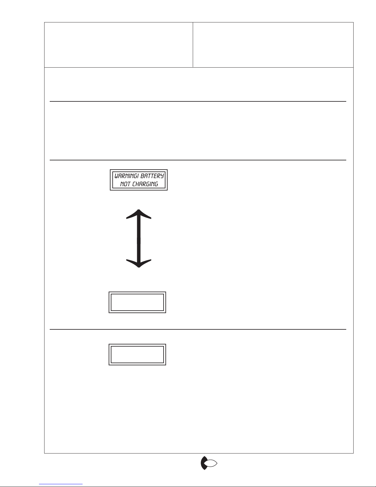
6. At this time, the power light should be
on and the LCD Display should read
one of two things:
OR
Either of these displays is normal.
See the following pages for system
operation and display modes.
1. Find a suitable place to set your “Smart
Charger” control unit. It is preferred that
the unit either be put up on blocks or on
a shelf designed to handle the weight of
the unit and battery. Figure E.
2. Once the unit is in place, run the pump
cord and the Auxiliary alarm/pump
switch cord to the left side of the “Smart
Charger” unit and plug them into the
corresponding sockets. Figures E & F
NOTE: Make sure that the plugs are
aligned properly before trying to plug them
in. DO NOT try to force the plugs into the
sockets.
3. Next remove the lid from the battery
enclosure, and move the battery leads
out of the way so that they do not
accidentally touch the battery posts
during installation.
4. Lower the battery into the enclosure
making sure that the terminals are
facing the front of the battery box. The
left battery post should be the positive
and the right should be the negative.
FIGURE E

Sump Boss
Metropolitan Industries, Inc.
www.metropolitanind.com
OPERATION MANUAL
Dated: 9/17/09
Supersedes: None
Document No.: SBossO&M Page 10 of 19
Register your product at
www.sumpro.com
SUMP BOSS FINAL SYSTEM CHECKLIST. Figures E & F.
Before going any further, check the following items:
□ Make sure the piping and check valve are tight and secure.
□ Make sure that the SUMP BOSS primary oat switch is set to go on at a higher level than
the primary pump switch and that the auxiliary oat switch is set to go on slightly above
the SUMP BOSS switch. FIGURE D.
□ Make sure the pump and auxiliary switch cords are plugged into their designated sockets
properly. FIGURES E & F.
□ Make sure that the battery leads are wired and tightened down properly, and that the
battery cover is in place. Figure F.
□ Make sure the unit is plugged into a 115v ac outlet and that there is power to that outlet.
Your SUMP BOSS is ready for nal testing!
FIGURE F

Sump Boss
Metropolitan Industries, Inc.
www.metropolitanind.com
OPERATION MANUAL
Dated: 9/17/09
Supersedes: None
Document No.: SBossO&M Page 11 of 19
Register your product at
www.sumpro.com
OPERATION OF THE SUMP BOSS &
“SMART CHARGER” SYSTEM.
SUMP BOSS TESTING
AND OPERATION
The SUMP BOSS Battery Pump System
is the most advanced system on the
market today. Its microprocessor-based
“Smart Charger” system, coupled with
the LCD display and alarm, allows it to
tell you in what state the system is at all
times. The following is a step-by-step
description of the LCD screens and alarm
codes for the system during normal AC
operation as well as during DC operation.
1. Unplug your primary pump and ll the pit
with water until the SUMP BOSS starts
pumping.
2. Check to make sure that the pump turns
on and off at the desired levels. If it
does not, adjust the rubber stops on the
oat rod by sliding them up or down to
achieve the desired level. Figure G.
3. Manually lift the oat on the
Auxiliaryalarm/pump switch to make
sure it is properly set and working. If this
switch needs further adjustment, loosen
the hose clamp on the bracket and slide
it up or down on the discharge pipe and
re-tighten it at the desired level.
NOTE: During the testing you will hear the
alarm sound. This is normal and will be ex-
plained in the next section.
CAUTION: DO NOT RUN THE PUMP
DRY! SERIOUS DAMAGE MAY OCCUR!
Always make sure there is sufcient water
in the basin before running the pump.

Sump Boss
Metropolitan Industries, Inc.
www.metropolitanind.com
OPERATION MANUAL
Dated: 9/17/09
Supersedes: None
Document No.: SBossO&M Page 12 of 19
Register your product at
www.sumpro.com
AC MODE (Green AC Indicator Light On) 115v AC (Line Power)
Screens and Alarm Codes
ALARM DISPLAY EXPLANATION
NO ALARM
NO ALARM
1-SECOND
BEEP AT
EACH PUMP
START -UP
CONTINUOUS
BEEPING
Screen One. This means that AC line power is present
and the battery is fully charged. No alarms should
sound.
Screen Two. This means the microprocessor has
determined the Battery is in need of a charge. This is
perfectly normal and will occur from time to time. No
alarm should sound.
Screen Three. This means that the pump is in use on
the AT EACH PUMP 115v AC line. Each time the pump
runs in this mode, the START-UP alarm will beep for
one second.
Screen Four. This screen will appear after Screen
Three has been on for three seconds. It will remain
on for ve seconds before alternating back to Screen
Three. These screens will only appear when the pump
is actually running off of the battery. This screen will tell
you the percent of battery life left in the DC mode under
true pump load, within the actual useable battery voltage
range. The reason this screen does not appear when
the pump is idle is that you will not get a true reading
when the battery is not being used, or under load.
Screen Five. This means that either the primary or
the auxiliary switch has turned on, but the pump is not
drawing any current. When this occurs Screen Five
will alternate with Screen Six every three seconds. This
scenario will sound a continuous beeping alarm. Screen
Six. This is the same scenario as mentioned on Screen
Five. If this alarm occurs one of the following items have
failed; check them in the following order:
1. The pump cord is not properly plugged into the con-
trol unit.
2. The primary switch has failed.
3. The Smart Charger is damaged. This could be
caused by a jammed impeller, or motor overheating.
CHECK PUMP
WIRE CONNECTIONS
Sump Boss
Metropolitan Industries, Inc.
www.metropolitanind.com
OPERATION MANUAL
Dated: 9/17/09
Supersedes: None
Document No.: SBossO&M Page 13 of 19
Register your product at
www.sumpro.com
ALARM DISPLAY EXPLANATION
4. The motor is damaged.
5. The brushes are worn out. This would
most likely occur in an older unit.
See Figure H.
Screen Six.This means that the
microprocessor has detected that the
battery is not taking a charge. When
this occurs Screen Six will alternate with
Screen Seven in three second intervals.
In most cases this means that either the
battery is in need of replacement, it is low
on water, or the battery terminals have
excessive corrosion on them. In rare cases
this may also mean that the Smart
Charger is damaged for some reason. This
scenario will sound a continuous beeping
alarm.
Screen Seven. This is the same scenario
as mentioned on Screen Six. Refer to
above paragraph.
CONTINUOUS
BEEPING
CONTINUOUS
BEEPING
WARNING! HIGH!
WATER ALERT!
Screen Eight. This means that the aux-
iliary alarm/pump switch has activated.
When this occurs one of two things
is happening:
1. The main pump switch has failed.
2. The water is coming into the basin
faster than the pump can pump it out.
This scenario will sound a continuous
beeping alarm.
CHECK BATTERY
AND CONNECTIONS

Sump Boss
Metropolitan Industries, Inc.
www.metropolitanind.com
OPERATION MANUAL
Dated: 9/17/09
Supersedes: None
Document No.: SBossO&M Page 14 of 19
Register your product at
www.sumpro.com
ALARM DISPLAY EXPLANATION
DC MODE (Green AC Indicator Light Off)
12VDC (Battery Power) Screens and Alarm Codes
NO ALARM Screen One. This means that the line power has
failed and that the Sump Boss is ready to operate
off of the battery. When this occurs Screen One
will alternate with Screen Two in three second
intervals. This scenario will not sound an alarm.
Screen Two. This is the same scenario as
mentioned for Screen One. Refer to above
paragraph.
POWER FAILURE
DETECTED!
(TWO) 1
SECOND
BEEPS AT
EACH PUMP
START -UP
Screen Three. This means that the primary
switch has turned on and the pump is operating.
Each time the pump runs in this mode the
alarm will beep twice.
Screen Four. This screen will appear after
Screen Three has been on for three seconds. It
will remain on for ve seconds before alternating
back to Screen Three. These screens will only
appear when the pump is actually running off of
the battery. This screen will tell you the percent
of battery life left in the DC mode under true pump
load, within the actual useable battery voltage
range. The reason this screen does not appear
when the pump is idle is that you will not get a
true reading when the battery is not being used,
or under load
BATTERY CAPACITY
IS AT 000%
CONTINUOUS
BEEPING
WARNING! PUMP
NOT OPERATING
CHECK PUMP
WIRE CONNECTIONS
Screen Five. This means that either the primary
or the auxiliary switch has turned on, but the
pump is not drawing any current. When this
occurs Screen Five will alternate with Screen Six
every three seconds. This scenario will sound a
continuous beeping alarm.
Screen Six. This is the same scenario as
mentioned on Screen Five. If this alarm occurs
one of the following items have failed; check
them in the following order:

Sump Boss
Metropolitan Industries, Inc.
www.metropolitanind.com
OPERATION MANUAL
Dated: 9/17/09
Supersedes: None
Document No.: SBossO&M Page 15 of 19
Register your product at
www.sumpro.com
1. The pump cord is not properly plugged into
the control unit.
2. The primary switch has failed.
3. The Smart Charger is damaged. This could
be caused by a jammed impeller, or motor
overheating.
4. The motor is damaged.
5. The brushes are worn out. This would most
likely occur in an older unit. See Figure H.
Screen Seven. This means that the auxiliary
alarm/pump switch has activated. When this
occurs one of two things is happening:
1. The main pump switch has failed.
2. The water is coming into the basin faster than
the pump can pump it out. This scenario will
sound a continuous beeping alarm. This
may also be caused by a depleted battery in
the DC mode. Turn on the pump and check
% of battery life left.
CONTINUOUS
BEEPING
WARNING! HIGH
WATER ALERT
This completes the operating scenarios of the SUMP BOSS system. As you can see, this
product was designed to be extremely user-friendly and should always warn and assist
you in resolving any problems that may occur during the life of this product.

Sump Boss
Metropolitan Industries, Inc.
www.metropolitanind.com
OPERATION MANUAL
Dated: 9/17/09
Supersedes: None
Document No.: SBossO&M Page 16 of 19
Register your product at
www.sumpro.com
!!!WARNING!!!
Before servicing this pump, always shut off the main power breaker and unplug the control
unit. Make sure you are not standing in water and are wearing insulated protective-soled
shoes. Under ooded conditions, contact your electric company or a qualied licensed
electrician for disconnecting electrical service prior to pump removal.
BRUSH REPLACEMENT
CAUTION: Disconnect 115V line power and
disconnect battery before servicing brushes!
FIGURE H

Sump Boss
Metropolitan Industries, Inc.
www.metropolitanind.com
OPERATION MANUAL
Dated: 9/17/09
Supersedes: None
Document No.: SBossO&M Page 17 of 19
Register your product at
www.sumpro.com
AUXILIARY POWER SYSTEM
INTRODUCTION:
Metropolitan SUMP BOSS Auxiliary Pump
System, BP 2000, is recommended as a
battery backup for residential sump pumps
and is not intended for use as an auxiliary
power system for appliances or other non-
sump pump electrical devices.
The above noted Metropolitan product
is guaranteed to be in perfect condition
when it leaves our factory. During the
time periods and subject to the conditions
hereinafter set forth, metropolitan Pump
Company, subsidiary of Metropolitan
Industries, Inc. will repair or replace to
the original user or consumer any portion
of your new Metropolitan product which
proves defective due to materials or
workmanship of Metropolitan. At all times
Metropolitan shall have and possess the
sole right and option to determine whether
to repair or replace defective equipment,
parts or components. Damage due to
lightning or conditions beyond the control
of Metropolitan is NOT COVERED BY
THIS WARRANTY. The warranty does not
cover any unit which has been damaged
either in transit or by misuse, accident or
negligence.
THIS WARRANTY WILL NOT APPLY:
1. To defects or malfunctions resulting
from failure to properly install, operate,
or maintain the unit in accordance with
printed instructions provided.
2. To failures resulting from abuse,
accident or negligence.
3. To units which are not installed in
accordance with applicable local codes,
ordinances and good trade practices.
4. If unit is used for purposes other
than for what it was designed and
manufactured.
5. If unit is exposed to, but not limited to,
the following: sand, gravel, cement,
grease, plaster, mud, tar, hydrocarbons
or hydrocarbon derivatives (oil,
gasoline, solvents, etc.) or other
abrasive or corrosive substances.
6. If power cord has been cut or the
grounding prong has been removed.
7. If unit has been dismantled by customer.
8. Batteries not meeting the above
specications have been used.
9. Unit has been submerged in water.
10.Unit has been applied to products
exceeding the maximum capacity of
the unit, as specied in the instructions
and on the unit front label.
11. Unit has been applied to the wrong
voltage.

Sump Boss
Metropolitan Industries, Inc.
www.metropolitanind.com
OPERATION MANUAL
Dated: 9/17/09
Supersedes: None
Document No.: SBossO&M Page 18 of 19
Register your product at
www.sumpro.com
12.Unit has been used in an outdoor
application.
13.Unit has been tampered with in any
manner not described in the preceding
instructions.
RETURNED OR REPLACED PRODUCT:
Any product to be replaced under
the Warranty must be returned to
Metropolitan Pump Company.
PRODUCT IMPROVEMENTS:
Metropolitan reserves the right to change
or improve its products or any portions
thereof without being obligated to provide
such a change or improvement for units
sold and/or shipped prior to such change
or improvement.
DISCLAIMER:
Any oral statements about the product
made by the seller, the manufacturer,
the representatives or any other parties,
do not constitute warranties, shall not
be relied upon by the user, and are not
part of the contract for sale. Seller’s and
manufacturer’s only obligation, and buyer’s
only remedy, shall be the replacement
and/or repair by the manufacturer of the
product as described above. Neither seller
nor the manufacturer shall be liable for any
injury, loss or damage, direct, incidental
or consequential damages for lost prots,
lost sales, injury to person or property, or
any other incidental or consequential loss
arising out of the use or the inability to
use the product, and the user agrees that
no other remedy shall be available to it.
Before using, the user shall determine the
suitability of the product for his intended
use, and user assumes all risk of liability
whatsoever in connection therewith. The
warranty and remedy described in this
limited warranty is an EXCLUSIVE warranty
and remedy and is IN LIEU of any other
warranty or remedy, expressed or implied,
which other warranties and remedies are
hereby expressly EXCLUDED, including
but not limited to any implied warranty of
MERCHANTABILITY OR FITNESS FOR
PARTICULAR PURPOSE. Some states
do not allow the exclusive or limitation of
incidental consequential damages, so the
above limitation or exclusion may apply
to you. This warranty gives you specic
legal rights, and may also have other rights
which vary from state to state.
In the absence of other suitable proof of
the installation date, effective date of the
warranty will be based upon the date of
manufacture plus one year.
Direct all Notices, etc. to:
Service Department
Metropolitan Pump Company, Inc.,
37 Forestwood Drive
Romeoville, IL 60446-1343

Sump Boss
Metropolitan Industries, Inc.
www.metropolitanind.com
OPERATION MANUAL
Dated: 9/17/09
Supersedes: None
Document No.: SBossO&M Page 19 of 19
Register your product at
www.sumpro.com
WARRANTY
1. Coverage and Term. Metropolitan Industries, Inc. (“Metropolitan”) warrants to the original purchaser (the “Buyer”) of
each Metropolitan product (the “product”), that any part thereof which proves to be defective in material or workmanship within
one (1) year from date of installation or 18 months from the date of manufacture, whichever comes rst, will be replaced at no
charge with a new or remanufactured part, F.O.B. factory. Buyer shall be responsible for all freight charges and all costs of eld
labor or other charges incurred in the removal and/or reinstallation of any product, part or component thereof.
2. Exclusions. THE WARRANTY IS SUBJECT TO THE FOLLOWING CONDITIONS AND EXCLUSIONS:
(a) The Warranty excludes products or workmanship which becomes defective as a result of: (i) earthquake, re,
storms, the elements or any other acts of God; (ii) normal wear and tear from use; (iii) accident, misuse, abuse or neglect ; (iv)
modications made by Buyer or any third party, other than Metropolitan; and (v) Buyer’s failure to properly install, maintain,
service and/or operate the product under normal conditions and according to manufacturer’s instructions.
(b) Metropolitan shall not be responsible for, and the Warranty shall not cover, extended damage which occurs
because of Buyer’s failure to notify Metropolitan promptly in writing of apparent defects.
(c) Any part or component designated as manufactured by anyone other than Metropolitan shall be covered only
by the express warranty of the manufacturer thereof.
(d) The Warranty shall lapse upon Buyer’s failure to fully comply with the terms and conditions of its contract
with Metropolitan, including Buyer’s failure to pay the purchase price for the product or any portion thereof. Buyer’s subsequent
compliance with the terms and conditions of any such contract, will not cause the term of the Warranty to extend beyond the time
period set forth above.
(e) No actions taken by Metropolitan to correct a defect in a product shall extend the Warranty beyond the period
set forth above. Metropolitan shall not be obligated to remedy any defect, where otherwise required pursuant to the Warranty
unless and until Buyer noties Metropolitan in writing of the defect and then only if such notication is made prior to the
expiration of the period set forth above.
3. Process of Claims and Repairs. Metropolitan agrees that if the product or any part or component thereof shall fail to
conform to the terms of this Warranty, Metropolitan shall replace such nonconforming product, part or component at the original
point of delivery and furnish instruction for its disposition. Any transportation charges involved in such disposition and all costs
of eld labor or other charges incurred in the removal and/or reinstallation of any product, part or component thereof shall be the
responsibility of Buyer.
4. Limitation on Liability. Notwithstanding any provision to the contrary, Metropolitan’s entire liability under this
Warranty shall not in the aggregate exceed, and Buyer’s exclusive and sole remedies are, to the extent permitted by law, shall be
to secure replacement of the defective product. UNDER NO CIRCUMSTANCES SHALL METROPOLITAN BE LIABLE
UNDER THE WARRANTY FOR ANY INDIRECT, PUNITIVE, SPECIAL, EXEMPLARY, CONSEQUENTIAL OR
INCIDENTAL DAMAGES (INCLUDING LOST PROFITS, REVENUE, USE OR ECONOMIC ADVANTAGE).
5. Express Waiver of Any Other Warranties. THE EXPRESS WARRANTY SET FORTH IN THIS WRITTEN
WARRANTY IS THE ONLY WARRANTY MADE BY METROPOLITAN, OR ANY OTHER PARTY, IN CONNECTION
WITH ANY PRODUCT PURCHASED FROM METROPOLITAN. NEITHER METROPOLITAN, NOR ANY OTHER
PARTY, MAKES ANY OTHER EXPRESS OR IMPLIED WARRANTY WHICH IS NOT SET FORTH HEREIN,
AND METROPOLITAN HEREBY DISCLAIMS AND BUYER HEREBY WAIVES ALL IMPLIED WARRANTIES,
INCLUDING THE IMPLIED WARRANTY OF MERCHANTABILITY AND THE IMPLIED WARRANTY OF
FITNESS FOR A PARTICULAR PURPOSE.
6. Not Transferable. The Warranty may not be transferred and shall be void on the sale or other transfer of the product.
7. Products and Warranty Subject to Change. Metropolitan reserves the right to make revisions to its products and their
specications, and to revise this Warranty and related information without notice.
Register your product at
www.sumpro.com
Table of contents


