ADVATEK LIGHTING PixLite T8-S Mk3 User manual

www.advateklights.com PixLite T8-S Mk3 User Manual V220211
PixLite T8-S Mk3 User Manual

- 2 -
www.advateklights.com PixLite T8-S Mk3 User Manual V220211
1 - Table of Contents
1 - Table of Contents 2
2 - Introduction 4
2.1 - Management &Configuration 4
3 - Safety Notes 5
4 - Physical Installation 6
4.1 - Wall/Ceiling/Universal Mount 6
4.2 - Direct Panel Mount 8
4.3 - 19” Rack Mount 10
4.3.1 - Single Controller Configuration 11
4.3.2 - Dual Controller Configuration 12
5 - Electrical Connections 15
5.1 - Supplying Power 15
5.2 - Control Data 15
5.3 - Connecting the Transmitter to Receivers 16
5.4 - Expanded Mode 17
6 - Network Configuration 19
6.1 - Network Layout Options 19
6.2 - IGMPSnooping 20
6.3 - Dual Gigabit Ports 20
6.4 - IPAddressing 21
6.4.1 - DHCP 21
6.4.2 - AutoIP 21
6.4.3 - Static IP 22
6.4.4 - Factory IPAddress 22
7 - Operation 24
7.1 - Start-up 24
7.2 - Sending Ethernet Data 24
7.3 - Data Outputs 24
7.4 - Aux Port 25
7.5 - Button Actions 25

- 3 -
www.advateklights.com PixLite T8-S Mk3 User Manual V220211
7.6 - Hardware Test Pattern 26
7.7 - Operating Refresh Rates 27
8 - Firmware Updates 28
8.1 - Updating via the Management Interface 28
9 - Specifications 29
9.1 - Operating Specifications 29
9.1.1 - Power 29
9.1.2 - Thermal 29
9.2 - Physical Specifications 29
9.3 - Electrical Fault Protection 30
10 - Troubleshooting 31
10.1 - LEDCodes 31
10.2 - Statistical Monitoring 33
10.3 - Solutions for Common Issues 33
10.4 - Other Issues 33
10.5 - Reset to Factory Defaults 34
11 - Disclaimer 35

- 4 -
www.advateklights.com PixLite T8-S Mk3 User Manual V220211
2 - Introduction
This is the user manual for the PixLite T8-S Mk3 pixel controller. The PixLite T8-S Mk3 is a
powerful pixel LED controller built upon Advatek’s 3rd generation PixLite Mk3 processor.
At its core, the controller converts sACN, Art-Net and DMX512 protocols from lighting
consoles, media servers or computer lighting software into various pixel
LEDprotocols. With the PixLite Mk3 processor, the PixLite T8-S Mk3 brings powerful
operational functionality and advanced management platforms.
2.1 - Management &Configuration
This manual covers physical aspects of the PixLite T8- S Mk3 controller and its
essential setup steps only. Detailed information about its configuration options can
be found in the ‘PixLite Mk3 Management Guide’.
Configuration, management, and monitoring of this device can be performed either
via the web-based Management Interface or using Advatek Assistant 3*. To access
the interface, open any web browser and navigate to the IP address of the device.
*At the time of writing this user manual, Advatek Assistant 3 has not been released. The method to
manage the device is via the Management Interface only at this stage.
Figure 1: Management Interface Home Page
Other manuals and the PixLite Mk3 Management Guide may be downloaded from:
www.advateklights.com/downloads

- 5 -
www.advateklights.com PixLite T8-S Mk3 User Manual V220211
3 - Safety Notes
Specification and certification markings are located on the rear of the device.
The device shall be connected to a mains socket outlet with a protective earthing
connection. The plug on the power supply cord is used as the disconnect device, so
the socket-outlet shall be easily accessible.
Power to the device is protected by a 250V 1A glass fuse (F1A L 250V). This fuse should
only be replaced by someone with proper technical knowledge or instruction.
For more information on supplying power, see Section 1.1.

- 6 -
www.advateklights.com PixLite T8-S Mk3 User Manual V220211
4 - Physical Installation
4.1 - Wall/Ceiling/Universal Mount
Use the optional mounting kit (part number MNT0301) to attach the controller to a
wall or ceiling.
1. Align the two plates in the mounting kit with the mounting holes on the
bottom side of the controller. Ensure the countersunk holes on the mounting
plates are aligned with the controller’s mounting holes.
2. Assemble the mounting plates onto the controller using the screws supplied
with the mounting kit, as shown in Figure 2 below.
Figure 2: Mounting Plates Assembled to Controller
3. Assemble the unit onto the wall / ceiling using four screws of a type suitable
for the mounting surface (not supplied), as shown in Figure 3 below. The
screws should be a pan head type, 4mm in thread diameter and at least
10mm long.

- 7 -
www.advateklights.com PixLite T8-S Mk3 User Manual V220211
Figure 3: Mounting Plates Assembled to Wall/Ceiling

- 8 -
www.advateklights.com PixLite T8-S Mk3 User Manual V220211
4.2 - Direct Panel Mount
1. Using the following drawing as location guide, drill four holes in your
mounting plate with a 4.5mm size drill, as shown in Figure 4 below.
Figure 4: Drilling Location Guide
2. From the bottom side of the panel, use four M4 machined thread screws to
assemble the controller to the panel, as shown in Figure 5 below. The screws
should be 8mm in length, plus the thickness of the panel.

- 9 -
www.advateklights.com PixLite T8-S Mk3 User Manual V220211
Figure 5: Controller Assembled onto Panel

- 10 -
www.advateklights.com PixLite T8-S Mk3 User Manual V220211
4.3 - 19” Rack Mount
The controller can be mounted in a 19” equipment rack in either of two configurations,
both taking up a single rack unit (1RU) height.
The first option is to mount a single controller in the middle of a rack slot, as shown in
Figure 6 below. Use optional mounting kit (part number MNT0201) for this
configuration.
Figure 6: Single Controller Rack Mount
The second option is to mount two controllers side by side in a single rack slot, as
shown in Figure 7 below. Use optional mounting kit (part number MNT0202) for this
configuration.

- 11 -
www.advateklights.com PixLite T8-S Mk3 User Manual V220211
Figure 7: Dual Controller Rack Mount
4.3.1 - Single Controller Configuration
1. Using the six supplied countersunk screws, assemble the two brackets to the
controller, as shown in Figure 8 below.
Figure 8: Single Brackets Assembled to Controller
2. Assemble the controller to the 19” rack using the supplied pan head screws,
washers and nuts, as shown in Figure 9 and Figure 10 below.

- 14 -
www.advateklights.com PixLite T8-S Mk3 User Manual V220211
Figure 13: Dual Controller Assembled to Rack

- 15 -
www.advateklights.com PixLite T8-S Mk3 User Manual V220211
5 - Electrical Connections
5.1 - Supplying Power
Power for the PixLite T8-S Mk3 controller is applied via the supplied AC power cable.
The controller is shipped with a 2m long IEC lead with a region specific power plug
which should be connected to the AC mains supply. The IEC input socket on the rear
of the enclosure, as shown in Figure 14 below, also contains an accessible
compartment with 250V 1A glass fuse (F1AL250V).
Refer to Section 9.1 for operating specifications for powering this device.
Figure 14: Location of Power Input
5.2 - Control Data
Ethernet data is connected via a standard network cable into either of the RJ45
Ethernet ports located on the rear panel of the unit, as shown in Figure 15 below.
Figure 15: Position of Ethernet

- 16 -
www.advateklights.com PixLite T8-S Mk3 User Manual V220211
5.3 - Connecting the Transmitter to Receivers
Receivers are connected to the transmitter via the RJ45 ports on the rear panel of the
PixLite T8-S Mk3. Each port is labelled with its output number 1-8. These ports are not
network ports, and should not be connected to any networking equipment, as shown
in Figure 16 below. They are specifically designed to connect a PixLite transmitter with
a PixLite receiver. For this reason, the standard network cable you use can safely be
up to 300m.
Figure 16: Correct equipment to use
The PixLite T8-S Mk3 may be connected to two different types of receivers. The first is
the PixLite R2F, which has 2 full pixel outputs (dedicated data and clock lines for each)
with both outputs individually fused.
The other receiver type is the PixLite R4D which has 4 dedicated data only pixels
outputs with each output individually fused. If using this receiver type, the PixLite T8-S
Mk3 unit should always be configured in the Management Interface to use expanded
mode (see Section 5.4 below). This setup is shown in Figure 17 below.
For further information relating to the receivers, please consult the specific user
manual for those products.

- 17 -
www.advateklights.com PixLite T8-S Mk3 User Manual V220211
Figure 17: Connecting Receivers to Transmitter
5.4 - Expanded Mode
If your pixels do not have a clock line, you may optionally activate expanded mode on
the controller, via the Management Interface. In expanded mode, the clock lines are
used as data lines instead. This means the controller effectively has twice as many
pixel outputs (32), but half as many pixels per output can be run. The PixLite R4D
receiver was specifically designed to take advantage of this mode and you will
always need to use the transmitter in this mode when using it.
Compared to pixels with a clock line, pixels that only use a data line have the
potential to lower the maximum achievable refresh rate in a pixel system. If a pixel
system is using data-only pixels, then the refresh rates will typically be improved by
using expanded mode. Enabling expanded mode allows for twice as many data
outputs, so the same number of pixels can be spread out over these outputs,
resulting in a large improvement to refresh rate. This becomes more important as the
number of pixels per output increases.

- 18 -
www.advateklights.com PixLite T8-S Mk3 User Manual V220211
Mapping of these pixel outputs in the Management Interface will appear as follows:
Expanded Mode Enabled
Management Interface Output T8 RJ45 Output R4 Pixel Output
1 1 1
2 1 2
3 1 3
4 1 4
5 2 1
6 2 2
7 2 3
8 2 4
etc.
Expanded Mode Disabled
Management Interface Output T8 RJ45 Output R2 Pixel Output
1 1 1
2 1 2
3 2 1
4 2 2
etc.

- 19 -
www.advateklights.com PixLite T8-S Mk3 User Manual V220211
6 - Network Configuration
6.1 - Network Layout Options
Figure 18: Network Layout using a Switch and Router
Figure 18 shows a typical network topology for the PixLite T8-S Mk3. Daisy-chaining
PixLite devices and redundant network loops are both explained in Section 6.3.
The Lighting Control Device could be any source of Ethernet data - e.g. desktop PC,
laptop, lighting console, or media server.
Having a router on the network is not mandatory but is useful for IP address
management with DHCP (see Section 6.4.1).

- 20 -
www.advateklights.com PixLite T8-S Mk3 User Manual V220211
Figure 19: Network Layout Without a Switch/Router
The controller can alternatively be connected directly to the host machine, as shown
in Figure 19. A crossover cable is not required in this case, but it may be used if
desired.
The controller(s) can be integrated straight into any pre-existing LAN such as your
media, home or office network, the above diagrams are only provided as examples.
6.2 - IGMPSnooping
Traditionally when multicasting a large number of universes, IGMPSnooping is
required to ensure that the pixel controller is not overwhelmed with irrelevant data.
However, the PixLite T8-S Mk3 is equipped with a Universe Data Hardware Firewall,
which filters out irrelevant incoming data, removing the need for IGMPSnooping.
6.3 - Dual Gigabit Ports
The two Ethernet ports are industry standard gigabit switching ports, so any network
device can be connected to either port. A common purpose for the two is to daisy-
chain PixLite Mk3 devices from the one network source, simplifying cable runs. The
combination of the speed of these ports and the included Universe Data Hardware
Firewall means that latency caused by daisy-chaining is practically negligible. For
any practical installation, an unlimited number of PixLite Mk3 devices can be daisy-
chained together.
A redundant network cable can be connected between the final Ethernet port in a
chain of PixLite Mk3 devices and a network switch. Since this will create a network
loop, it is important that the network switches being used support Spanning Tree
Protocol (STP), or one of its variants such as RSTP. STP will then allow this redundant
loop to be automatically managed by the network switch. Most high-quality network
switches have a version of STP built in and the configuration required is either none or
Other manuals for PixLite T8-S Mk3
3
Table of contents
Other ADVATEK LIGHTING Controllers manuals
ADVATEK LIGHTING
ADVATEK LIGHTING PixLite 16 Long Range User manual
ADVATEK LIGHTING
ADVATEK LIGHTING PixLite 4 Mk2 ECO User manual
ADVATEK LIGHTING
ADVATEK LIGHTING PixLite T8-S Mk2 User manual
ADVATEK LIGHTING
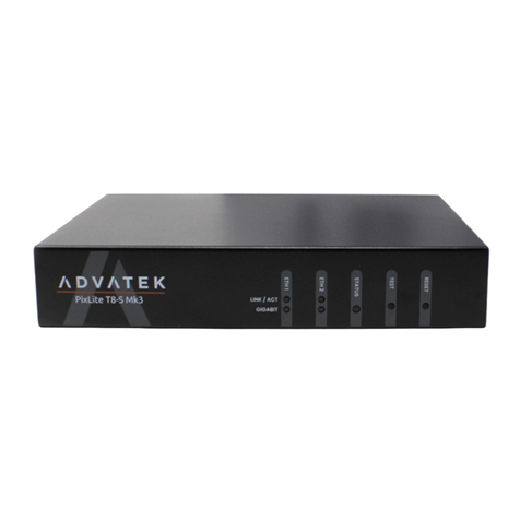
ADVATEK LIGHTING PixLite T8-S Mk3 User manual
ADVATEK LIGHTING
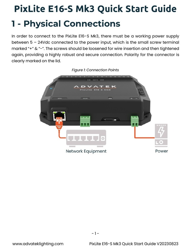
ADVATEK LIGHTING PixLite E16-S Mk3 User manual
ADVATEK LIGHTING
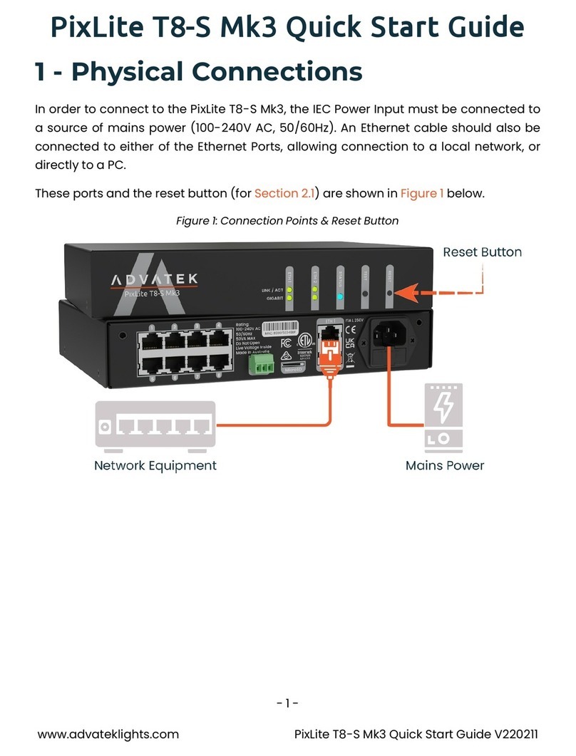
ADVATEK LIGHTING PixLite T8-S Mk3 User manual
ADVATEK LIGHTING
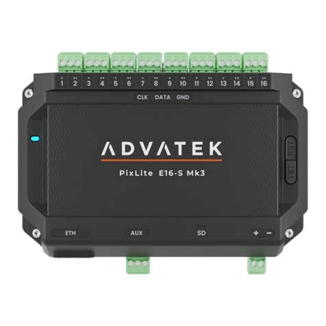
ADVATEK LIGHTING PixLite E16-S Mk3 User manual

ADVATEK LIGHTING
ADVATEK LIGHTING PixLite T8-S Mk3 User manual

ADVATEK LIGHTING
ADVATEK LIGHTING PixLite A4-S Mk3 User manual

ADVATEK LIGHTING
ADVATEK LIGHTING PixLite A4-S Mk3 User manual


