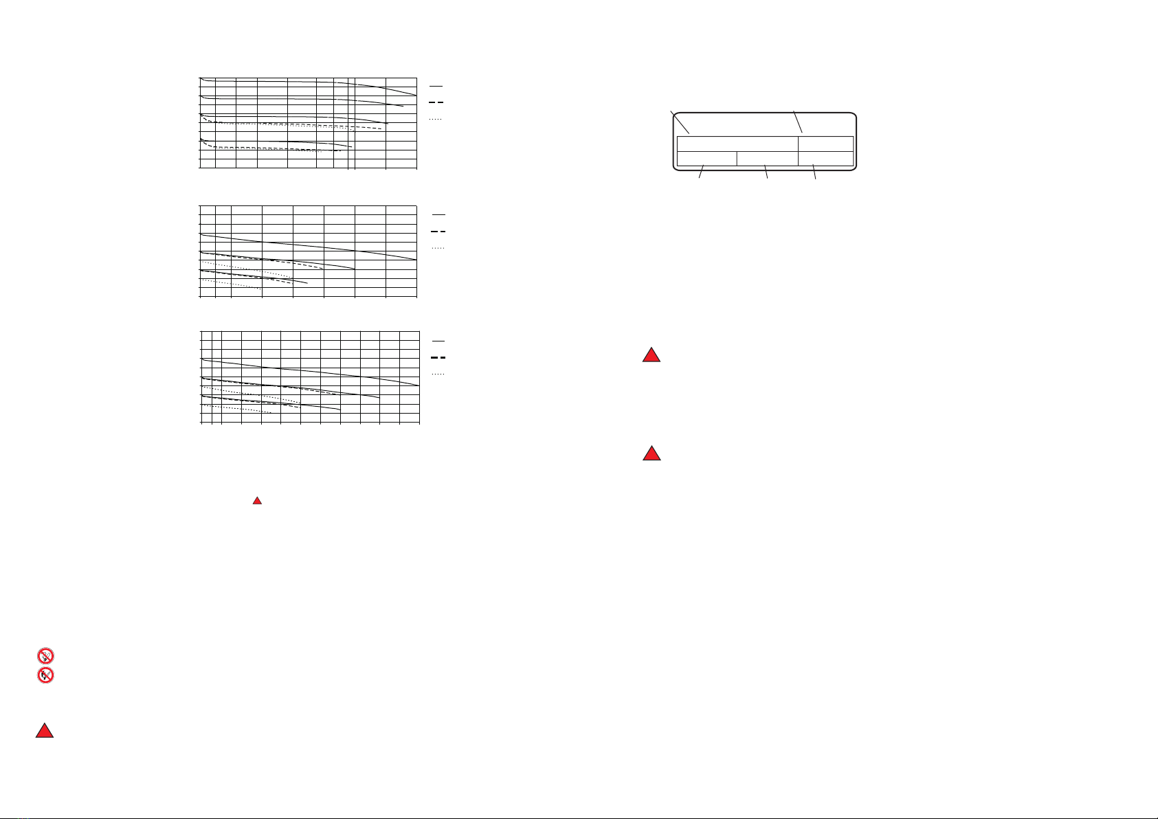
®
Megapur
pressure regulator
E71
outlet pressure p [ bar ]
h
0
2
4
6
7
8
9
10
5
3
1
0530 40 50 70
10 20 60
p =5 bar
v
p =7 bar
v
p =10 bar
v
p =5 bar
v
p =7 bar
v
p =10 bar
v
®
Megapur
pressure regulator
E61
outlet pressure p [ bar ]
h
p =21 bar
v
p =13 bar
v
p =7 bar
v
0 0,2 1 2 3 10 200,3 0,5 4 5
0
2
4
6
7
8
9
10
5
3
1
®
Megapur
pressure regulator
E81
outlet pressure p [ bar ]
h
flow rate Q
[ Nm³/h N ]
2
flow rate Q
[ Nm³/h N ]
2
flow rate Q
[ Nm³/h N ]
2
3. Labeling
4. Installation
Any gas-welted parts are cleaned with aqueous solutio
4.1
4.2
In case of a damage, the pressure regulator must not be connected.
4.3
4.4
4.5
n (free of halocarbons), heated in
a drying stove, mounted in a clean room class 100 and packed in foil in an inert gas
atmosphere . The fittings should be unpacked immediatly before mounted.
4.6 Hold the pressing screw when mounting the VCR-connections. Finger tighten the
nut with an internal thread .Then mark the nut with an internal thread and the
pressing screw. While holding the pressing screw with a wrench, further tighten the
1
nut with a wrench / turns, if the seal is made of stainless steal or nickel.
8
Caution: If the nut is overtighten, the sealing surfaces get damaged and leakages are
possible.
Before starting read the specifications of this instruction for use and observe it
while working.
Check, that the shut-off valve connections are without any damage (blow through if
nessesary).
When installing the pressure regulator in a pipe-line it is essential to ensure that the
pipe axes coincide with the connection axes of the regulator.
Before mounting, check that the threads and the connection seals are in perfect
condition.
A shut-off valve should be arranged in the supply line of the pressure regulator, so
that the pressure gauge of the regulator can be observed when opening the shut-off
valve.
2. Safety instructions
2.1
2.2 This pressure regulator correspond to state-off-the-art technology and to the
demands of the existing standards and regulations
2.3
2.4
2.5 Attention has to be paid to the country specific lawsb and regulations procedures
concerning the use of this equipment.
2.6
2.7
2.8
2.9
.
All items of information marked are valid as special safety instructions.
Changes or modifications to the tapping point pressure regulator must not be made
without the prior consent of the manufacturer.
The result of improper handling and non-designated use can involve risks for the
user and other persons as well as damage to the device.
All parts coming into contact with oxygen must be kept free of oil and grease!
Fire or explosion hazard!
Smoking or open fires in the vicinity of the oxygen supply system is strictly
prohibited!
Fire or explosion hazard!
This pressure regulator must only be used for the gas type that the device was
initially put into service for. Alternating use of the device for different gases is not
permitted.
The pressure regulator must not be exposed to ambient temperatures below -30°C
and above +60°C
!
!
!
!
!
LE 61
P1: 200 bar P2: 10 bar
770. …
0110
12
345
1 type
2 article-no.
3 max. inlet pressure
4 max. outlet pressure
5 date of manufacture
5. Start-up
Avoid an audible vibration
while filling the outlet line up.
Screw in the hand knob of the pressure regulator half of the maximum way.
Then open the high pressure shut-off valve slightly (only a fraction of a turn for small
flow rates), so that the inlet pressure of the regulator rises slowly to its full value and
the outlet pressure to approx, half of the maximum value.
After this filling procedure is completed, open the high pressure shut-off valve fully.
Adjust the outlet pressure with the hand knob. Open the low pressure shut-off valve
and, when the required flow rate has been reached, readjust the outlet pressure with the
hand knob.
0
2
4
6
7
8
9
10
5
3
1
0530 40 50 70
10 20 80 90 100 110
60
- 2 - - 3 -


