manuals.online logo
Brands
  1. Home
  2. •
  3. Brands
  4. •
  5. metso automation
  6. •
  7. Valve Positioner
  8. •
  9. metso automation IMO-596 Operating and maintenance manual

metso automation IMO-596 Operating and maintenance manual

IMO - 596 Issue Date: 12/01
INSTALLATION, MAINTENANCE, AND
OPERATING INSTRUCTIONS
FEEDBACK
POTENTIOMETER KIT
FOR ERV ELECTRIC
ACTUATORS
Read entire instructions carefully before installation or servicing
1GENERAL
This instruction manual contains important information
regarding the installation, maintenance, and troubleshooting
of the Jamesbury ERV Electric Actuator Feedback
Potentiometer option. Please read these instructions
carefully and save them for further reference.
The Jamesbury ERV Series Actuators can be equipped with
a 1000 Ohm Feedback Potentiometer, whenever remote
indication of valve position through its full rotation is
required. This external tracking signal is variable and
proportional to the output position of the actuator.This kit
is designed for 90° rotation.
1.2 Caution
Whenever an actuator is to be removed from the valve and
then remounted, the limit switch settings must be checked
to make sure the valve is making the proper travel.
Reference IMO-593 for cam adjustment instructions.When
servicing a valve/actuator assembly, the best practice is to
remove the entire assembly from service.Refer to the valve
INSTALLATION and MAINTENANCE Sections before
removing valve from the line.
1.3 General Technical Information
The standard configuration of the Feedback
Potentiometer provides 40” #22AWG wire leads for
termination outside of the actuator enclosure. For
termination inside the actuator enclosure, a 12-position
terminal block is required (Kit Number EK5117).
2 INSTALLATION
To remove the cover, remove the cover hold down screws.
EXTREME CARE MUST BE TAKEN TO AVOID ANY
DAMAGE TO MATING SURFACES. SCRATCHES OR NICKS
WOULD VIOLATE THE HAZARDOUS LOCATIONS
RATINGS OF THE ACTUATOR.
When reinstalling the cover, care must be taken not to
allow the cover to cock in relation to the base. Care must
be taken during the reassembly so that no particles or dirt
are on the mating surfaces of the flanges. Replace cover
and cover hold down screws. Tighten one screw partially,
then another on the opposite side of the flange, repeating
this procedure until all screws are partially tightened.
Repeat this procedure to fully tighten all screws.
1.1 WARNING
1. REMOVING THE COVER, SHUT OFF ALL ELECTRICAL POWER AND
DISCONNECT ALL CONNECTIONS.
2. TO PREVENT IGNITION OF HAZARDOUS ATMOSPHERES, DISCON-
NECT SUPPLY CIRCUIT BEFORE OPENING UNIT. KEEP ASSEMBLY
TIGHTLY CLOSED WHEN IN OPERATION.
3. TO MAINTAIN THE HAZARDOUS LOCATION RATING OF THE ERV
ACTUATOR, IT IS ESSENTIAL THAT THE MATING OF THE SURFACES
OF THE FLANGES BE PROTECTED FROM NICKS AND SCRATCHES
WHILE DISASSEMBLED. UPON REASSEMBLY, THERE MUST NOT BE
ANY DIRT OR PARTICLES ON THE MATING SURFACES OR
FLANGES.
1. Remove 5/16” (7.9 mm) locking nut (1) from poten-
tiometer shaft and insert shaft up through either 5/16”
(7.9 mm) hole in the upper support bracket. Align
locking tab and tighten the locking nut on poten-
tiometer shaft to secure it on the bracket.
2. Using spacer under gears to attain proper alignment,
place small (2) (20 tooth,See Figure 2) gear on poten-
tiometer and tighten set screw. Then place large (3)
(48 tooth, See Figure 2) gear on camshaft. when
properly positioned, gears should mesh evenly. The
cam shaft must extend a minimum of 1/8” (3.2 mm)
above gear in order to engage position indicator.
3. Apply power (or use the manual override) to drive the
actuator to the true closed position (clockwise rotation).
Connect an ohmmeter to the black and red pot leads.
Gently rotate the cam gear clockwise until the ohmmeter
reads 50 ohms (±5 ohms). While maintaining this
reading, tighten the cam set screw.
4. Apply power (or use the manual override) to drive the
actuator to the true open position. Connect the ohm-
meter to the black and green pot leads. The reading
should be between 35 and 60 ohms. If not,repeat Step
3 until proper calibration is achieved.
2.1 PARTS LIST
3 REPAIR KITS/SPARE PARTS
For further information or assistance on repair kits and
spare parts visit our website at www.Jamesbury.com.
Figure 2
PARTS LIST
ITEM PART NAME QTY
IMO-596 1
Wrench 1/16”(1.6 mm) 1
Wrench 0.035”(.889 mm) 1
Gear, Potentiometer, 20 tooth 1
Gear, Potentiometer, 48 tooth 1
Spacer, Cam Gear; Potentiometer Gear 1
Feedback Potentiometer, Sub-Assembly 1
Tools Required:
5/16” (7.9 mm) Wrench
Phillips Screw Driver #1 (for optional terminal block)
Figure 2
1
2
4
3
4
Metso Automation, Field Systems Division
Europe, Levytie 6, P.O.Box 310, 00811 Helsinki, Finland. Tel. int. +358 20 483 150. Fax int. +358 20 483 151
Europe (UK), 8 Pipers Wood Industrial Park, Waterlooville, Hampshire PO7 7XU UK. Tel. int. +44 (0)23 9223 8500. Fax int. +44 (0)23 9223 8510
North America, 44 Bowditch Drive, P.O.Box 8044, Shrewsbury, Massachusetts, 01545-8044 USA. Tel. int. +1 508 852 0200. Fax int. +1 508 852 8172
North America, 3100 Medlock Bridge Road, Suite 250, Norcross, GA 30071, USA. Tel. int. +1 770 446 7818. Fax int. +1 770 242 8386
Latin America, Av. Central, 181- Cháracas Reunidas, 12238-430, São Jose dos Campos. Tel. int. +55 12 335 3500. Fax int. +55 12 335 3535
Asia Pacific, 501 Orchard Road, #05-09 Wheelock Place, 238880 Singapore. Tel. int. +65 735 5200. Fax int. +65 735 2955
www.jamesbury.com
IMO-596-12/01 © 2001 Metso Automation Printed in U.S.A.-M-J

Other metso automation Valve Positioner manuals

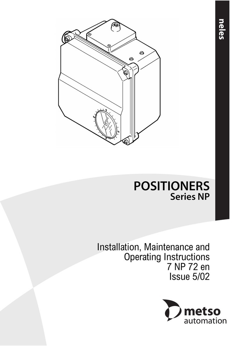
metso automation neles NP Series Operating and maintenance manual

metso automation

metso automation neles NP Series Operating and maintenance manual

Popular Valve Positioner manuals by other brands

PI M-110.*DG1 series user manual

PI

PI M-110.*DG1 series user manual

MOTOYAMA EA91A instruction manual

MOTOYAMA

MOTOYAMA EA91A instruction manual

Ytc YT-3300 Series product manual

Ytc

Ytc YT-3300 Series product manual

Flowserve Logix 3200IQ Technical bulletin

Flowserve

Flowserve Logix 3200IQ Technical bulletin

API API 3200 G Series instructions

API

API API 3200 G Series instructions

Axis T99A11 installation guide

Axis

Axis T99A11 installation guide

Emerson Fisher 3710 instruction manual

Emerson

Emerson Fisher 3710 instruction manual

ARCA 824 series operating manual

ARCA

ARCA 824 series operating manual

rotork YT-1200 Series product manual

rotork

rotork YT-1200 Series product manual

Parker 404 product manual

Parker

Parker 404 product manual

Festo CMSH manual

Festo

Festo CMSH manual

rotork YT-3302 Series product manual

rotork

rotork YT-3302 Series product manual

Seg SP740 Series instruction manual

Seg

Seg SP740 Series instruction manual

Samson TROVIS 3730-3 Mounting and operating instructions

Samson

Samson TROVIS 3730-3 Mounting and operating instructions

Baker Hughes Masoneilan 7700P instruction manual

Baker Hughes

Baker Hughes Masoneilan 7700P instruction manual

KMC Controls CMC-1001 installation guide

KMC Controls

KMC Controls CMC-1001 installation guide

PI P-62 Series user manual

PI

PI P-62 Series user manual

Westlock 793 Installation, setting, operation

Westlock

Westlock 793 Installation, setting, operation

manuals.online logo
manuals.online logoBrands
  • About & Mission
  • Contact us
  • Privacy Policy
  • Terms and Conditions

Copyright 2025 Manuals.Online. All Rights Reserved.