tissin TS610 Series User manual
Pneumatic Positioner
TS610 Series
Instruction Manual
Ver. PM-TS610EN_08/2023

2
P-P Positioner
TS610 Series
tissin
Table of Contents
1 Introduction-------------------------------------------------------------------------------------- 3
1.1 General information for the user--------------------------------------------------------- 3
1.2 Limited warranty and disclaimer---------------------------------------------------------- 3
1.3 Requirement for safety--------------------------------------------------------------------- 4
2 Product---------------------------------------------------------------------------------------------- 5
2.1 Function---------------------------------------------------------------------------------------- 5
2.2 Features---------------------------------------------------------------------------------------- 5
2.3 Options----------------------------------------------------------------------------------------- 5
2.4 Applications----------------------------------------------------------------------------------- 5
2.5 Label-------------------------------------------------------------------------------------------- 6
2.6 Product code---------------------------------------------------------------------------------- 7
2.7 Specification----------------------------------------------------------------------------------- 8
2.8 Operation Logic------------------------------------------------------------------------------ 9
2.9 Exploded view drawing--------------------------------------------------------------------- 10
2.10 Dimension------------------------------------------------------------------------------------- 11
3
Installation
---------------------------------------------------------------------------------------- 12
3.1 Safety------------------------------------------------------------------------------------------- 12
3.2 TS610L Linear type-------------------------------------------------------------------------- 12
3.3 TS610R Rotary type------------------------------------------------------------------------- 14
4 Air connection--------------------------------------------------------------------------------- 15
4.1 Before the air connection------------------------------------------------------------------ 15
4.2
TS610L air connection----------------------------------------------------------------------
--
15
4.3 TS610L RA/DA settings-------------------------------------------------------------------- 15
4.4 TS610R air connection--------------------------------------------------------------------- 16
4.5 TS610R RA/DA settings-------------------------------------------------------------------- 16
5 Adjustment--------------------------------------------------------------------------------------- 17
6 Troubleshooting----------------------------------------------------------------------------- 18
6.1 Common problems-------------------------------------------------------------------------- 18
6.2 Orifice Installation---------------------------------------------------------------------------- 18
6.3 Other problems and solutions------------------------------------------------------------- 19

3
P-P Positioner
TS610 Series
tissin
1 Introduction
1.1 General information for the user
This instruction includes installation, operation, maintenance, and parts information for Tissin
TS610 Valve Positioner. Keep these instructions in a location which is easily accessible to
every user and make these instructions available to every new owner of the device.
Installation, commissioning and maintenance of the product may only be performed by
trained specialist personnel who have been authorized by the plant operator to do so.
To avoid possible injury to personnel or damage to valve parts, WARNING, CAUTION
and NOTICE should be strictly followed.
Before installing or commissioning, be sure to read and thoroughly understand the
product manual and operate the product properly.
Operators must strictly observe the applicable national regulations with regards to
installation, function tests, repairs, and maintenance of electrical products.
For additional information or if specific problems occur that are not discussed in these
instructions, contact the manufacturer.
The manual can be altered or revised without any prior notice.
Please visit our website (http://www.tissin.co.kr ) check the latest documentation.
1.2 Limited warranty and disclaimer
The manufacturer warranty period of the product is 18 months after the product is
shipped from Tissin in Korea.
For any failure or damage reported within the warranty period which is clearly our
responsibility, a replacement product or necessary parts will be provided. This limited
warranty applies only to our product independently, and not to any other damage
incurred due to the failure of the product.
Using the device in a manner that does not fall within the scope of its intended use,
disregarding this manual, using under unqualified personnel, or making unauthorized
alterations releases the manufacturer from liability for any resulting damage. This
renders the manufacturer's warranty null and void.

4
P-P Positioner
TS610 Series
tissin
1.3 Requirement for safety
This manual contains notices you have to observe in order to ensure your personal safety, as
well as to prevent damage to property. These safety instructions are intended to prevent
hazardous situations and/or equipment damage. For the safety, it is important to follow the
instructions in the manual.
WARNING Failure to observe the warning may result in serious injuries or death.
CAUTION Failure to observe this warning may result in product failure or injuries.
NOTICE Failure to observe this warning may result in product failure or performance
degradation.
CAUTION
Only trained and authorized person should operate machinery and equipment.
Do not use this positioner out of the range of its specifications as this can cause failure.
Do not service or attempt to remove product and machinery/equipment until safety is
confirmed.
Before loosening the pneumatic lines and valves, turn off the pressure and vent the
pneumatic lines.

5
P-P Positioner
TS610 Series
tissin
2 Description of products
2.1 Function
Pneumatic valve positioner TS610 series product is a control device for control valves that
receives a 0.02~0.1 MPa pneumatic signal from a pneumatic output device (ex. Control room,
IP convertor) and proportionally adjusts the opening degree of the valve by adjusting the
supply pressure supplied to the valve actuator.
2.2 Features
Applied to various control valve system
Fast response time, excellent stability and durability
Simple zero and span adjustment
IP 66 enclosure
Easy maintenance due to built-in module type
By-pass valve (A/M switch) installed
2.3 Options
Position transmitter (4~20mA DC Feedback signal)
Limit switch (Mechanical or Proximity type)
2.4 Applications
TS610 series are mounted on Control valves and are used for fluid control in industrial
parts.
Oil and gas
Chemicals
Power plant
Paper
Water treatment
Pharmaceutical
Printing and dyeing processing
Food and beverage
Etc.
6
P-P Positioner
TS610 Series
tissin
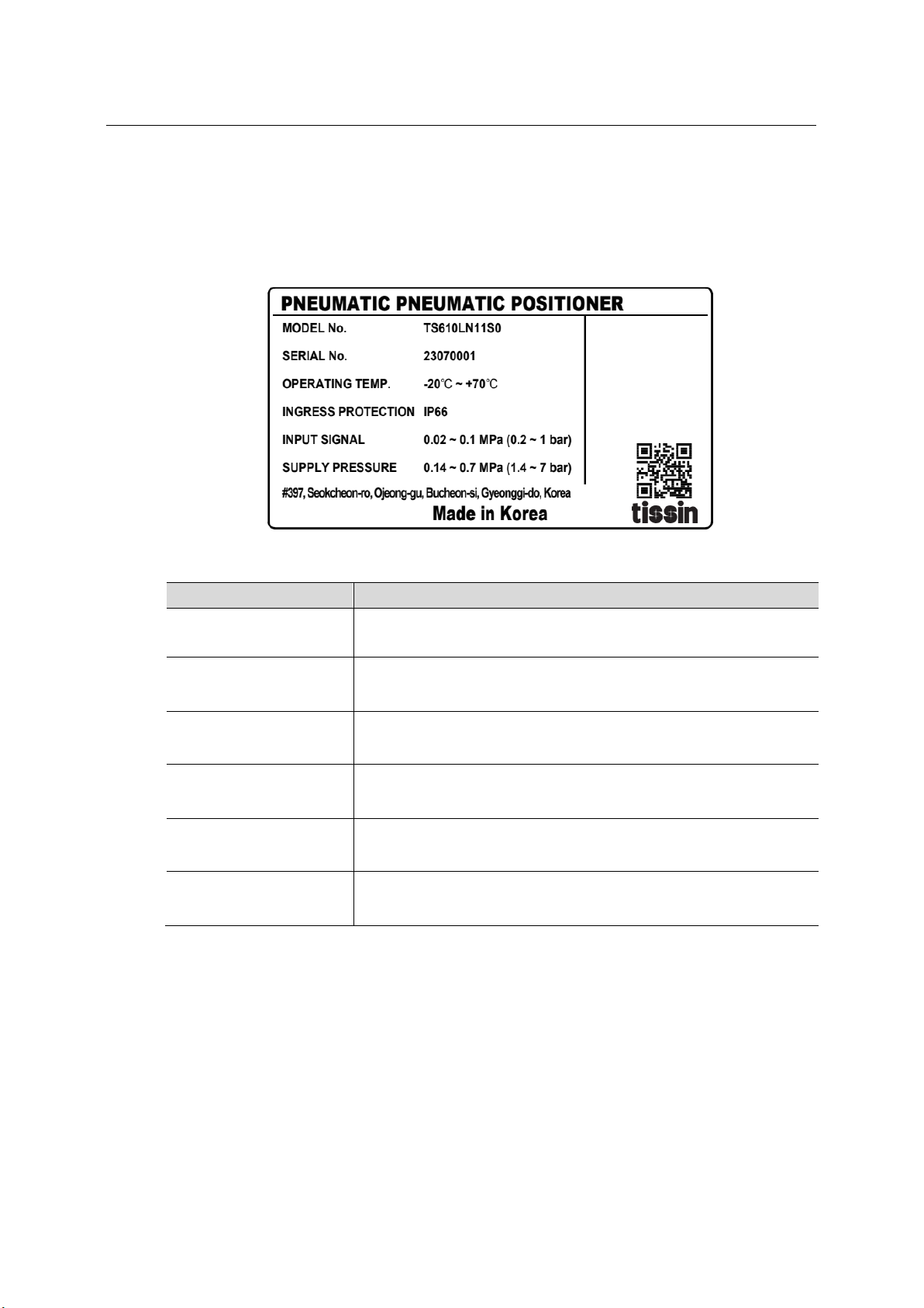
2.5Label
Item Description
MODEL No. Indicates model number.
SERIAL No. Indicates serial number.
OPERATING TEMP. Indicates allowable operating temperature.
INGRESS
PROTECTION Indicates enclosure IP grade.
INPUT SIGNAL Indicates pneumatic input signal range.
SUPPLY PRESSURE Indicates supply pressure range.

7
P-P Positioner
TS610 Series
tissin
2.6Product Code
Model TS610
Acting type Linear type L
Rotary type R
Connection type PT1/4 1
NPT1/4 2
G1/4 3
Lever type (Linear)10~40mm 1
40~70mm 2
70~100mm 3
100~150mm 4
1
Lever type (Rotary)M6 x 39L (Fork lever type)
NAMUR Type 5
Operating temp. -20~70℃(standard) S
-20~120℃H
-40~70℃L
-60~70℃(for EAC certificate) U
Options None 0
With Dome cover 1
External Position transmitter (+TS500) 2
External Position transmitter (+TS510) 3
External Limit switch (+TS400) 4
External Limit switch (+TS410) 5
External Position transmitter and Limit switch (+TS510)
6
With Limit switch mounting device 7
*Note : Option no. 1~7 are only available with TS610R (Rotary type).

8
P-P Positioner
TS610 Series
tissin
2.7Specification
TS610(Single) TS610(Double)
Input signal 0.02~0.1MPa
Supply pressure 0.14~0.7MPa
Stroke 10~150mm (Linear type), 0~900 (Rotary type)
Air connection PT1/4, NPT1/4, G1/4
Gauge connection NPT1/8
Enclosure IP66
Ambient temp. -20℃∼70℃(standard)
Linearity ±1.0% F.S ±2.0% F.S
Sensitivity ±0.2% F.S ±0.5% F.S
Hysteresis ±1.0% F.S
Repeatability ±0.5% F.S
Air consumption Below 2.5LPM (Sup=0.14MPa)
Flow capacity Over 80LPM (Sup=0.14MPa)
Material Aluminum die cast
Paint Polyester powder coating
Weight 2.8kg
9
P-P Positioner
TS610 Series
tissin
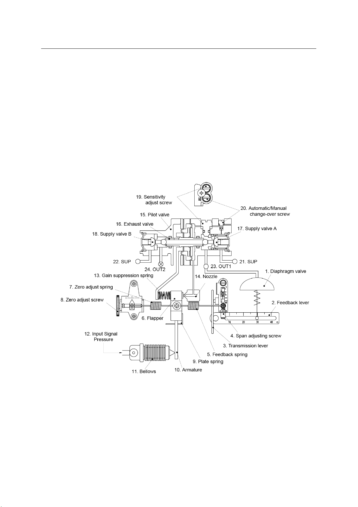
2.8 Operation Logic
If (12)Input signal pressure(0.02~0.1MPa) increase, (11)Bellows pushes (10)Armature in the
right direction and (6)Flapper moves left around (9)Plate spring. The gap between (6)Flapper
and (14)Nozzle lowers the nozzle back pressure and reduces the internal pressure of (15)Pilot
valve connected to (14)Nozzle, causing (16)Exhaust valve to move to the right. At the same
time, (17)Supply valve A on (23)OUT1 also moves to the right to open (17)Supply valve A.
(21)SUP increases the pneumatic pressure to (1)Diaphragm valve via (17)Supply valve A and
(23)OUT1, and moves (1)Diaphragm valve down. The movement of the valve is transmitted to
(5)Feedback spring via (2)Feedback lever and eventually increases the force to pull (6)Flapper
to the right. (1)Diaphragm valve is balanced at a position that is equilibrium with the force of
(11)Bellows contraction and expansion generated by the force of (5)Feedback spring and
(12)Input signal pressure above. (13)Gain suppression spring is intended to immediately
feedback the movement of (15)Pilot valve to (6)Flapper, which improves the stability of the loop.
* The above description is based on the TS610L linear type and Reverse Action (RA) type
diaphragm valve. TS610R rotary type has different feedback part structure and the operating
logic is same.
* Nozzle back pressure : Pressure inside Nozzle caused by the degree to which Flapper
controls Nozzle
* Loop : Positioner and Control valve form a closed circuit through Feedback lever
10
P-P Positioner
TS610 Series
tissin
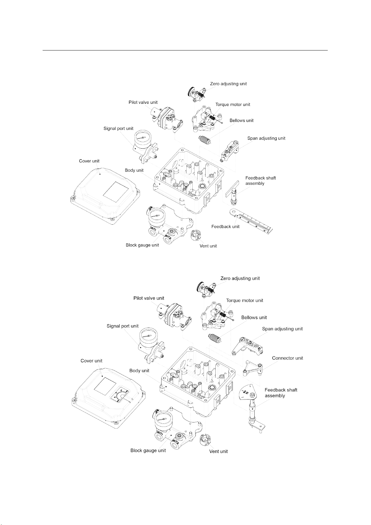
2.9Exploded-view drawing
<TS610L linear type>
<TS610R Rotary type>

11
P-P Positioner
TS610 Series
tissin
2.10 Dimension
2.10.1 TS610L Dimension
2.10.2 TS610R Dimension
12
P-P Positioner
TS610 Series
tissin
3 Installation
3.1 Safety
WARNING
Before installation, make sure that TS610 meets the valve and actuator installation
conditions and field requirements.
Incorrect installation may result in bad TS610 control characteristics.
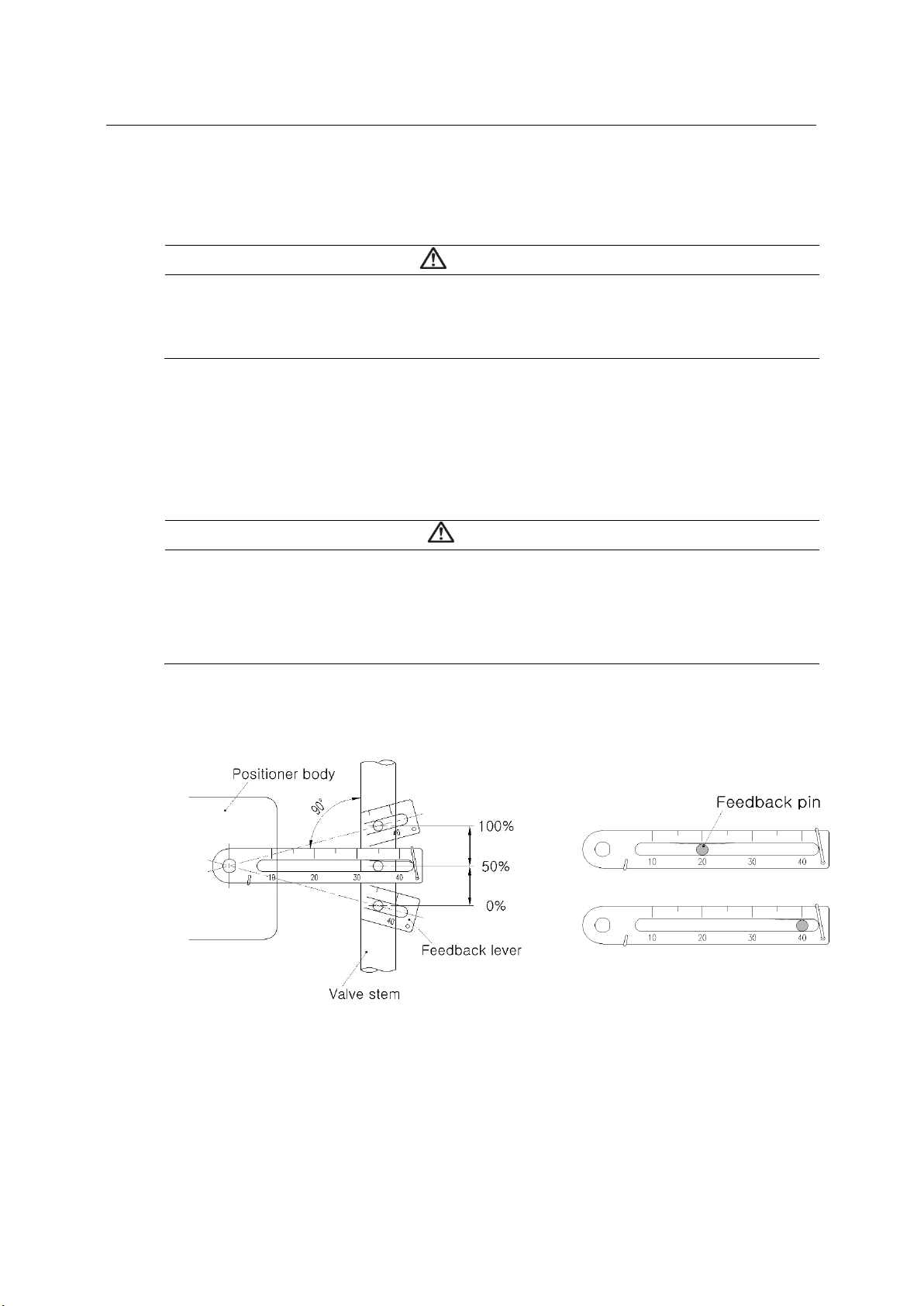
3.2 TS610L linear type
When making mounting brackets and fastening levers to the actuator stem, the following two
must be observed. Otherwise, it can affect the performance of the product, such as linearity.
<Figure 1> <Figure 2>
CAUTION
①
Check if Feedback lever is parallel to the ground at 50% of the valve stroke. <Figure 1>
②Feedback lever connection with the pin of the actuator clamp should be installed in such
a way that the valve’s total stroke and numbers which indicated on the feedback lever
must be fitted. <Figure 2>
13
P-P Positioner
TS610 Series
tissin
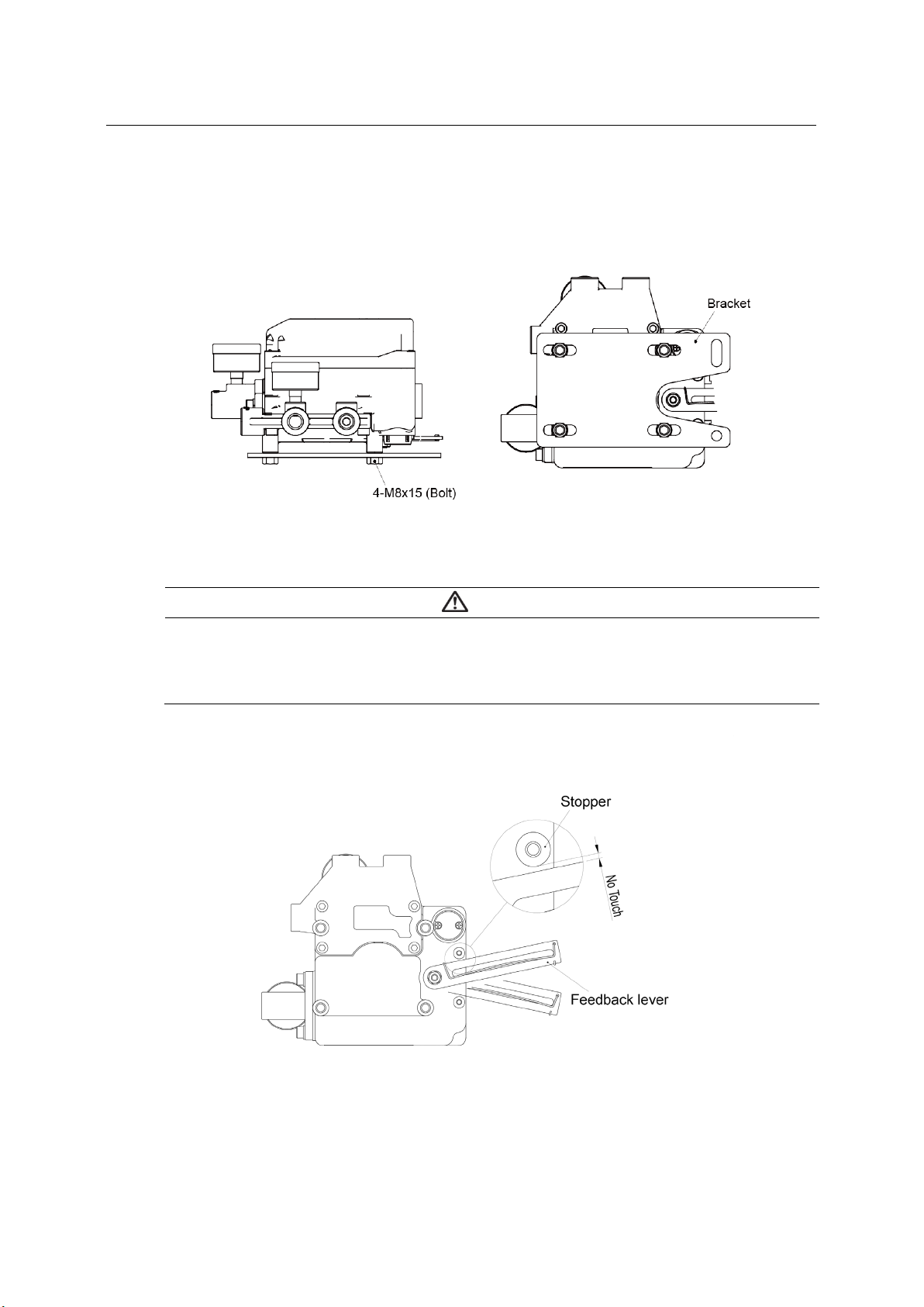
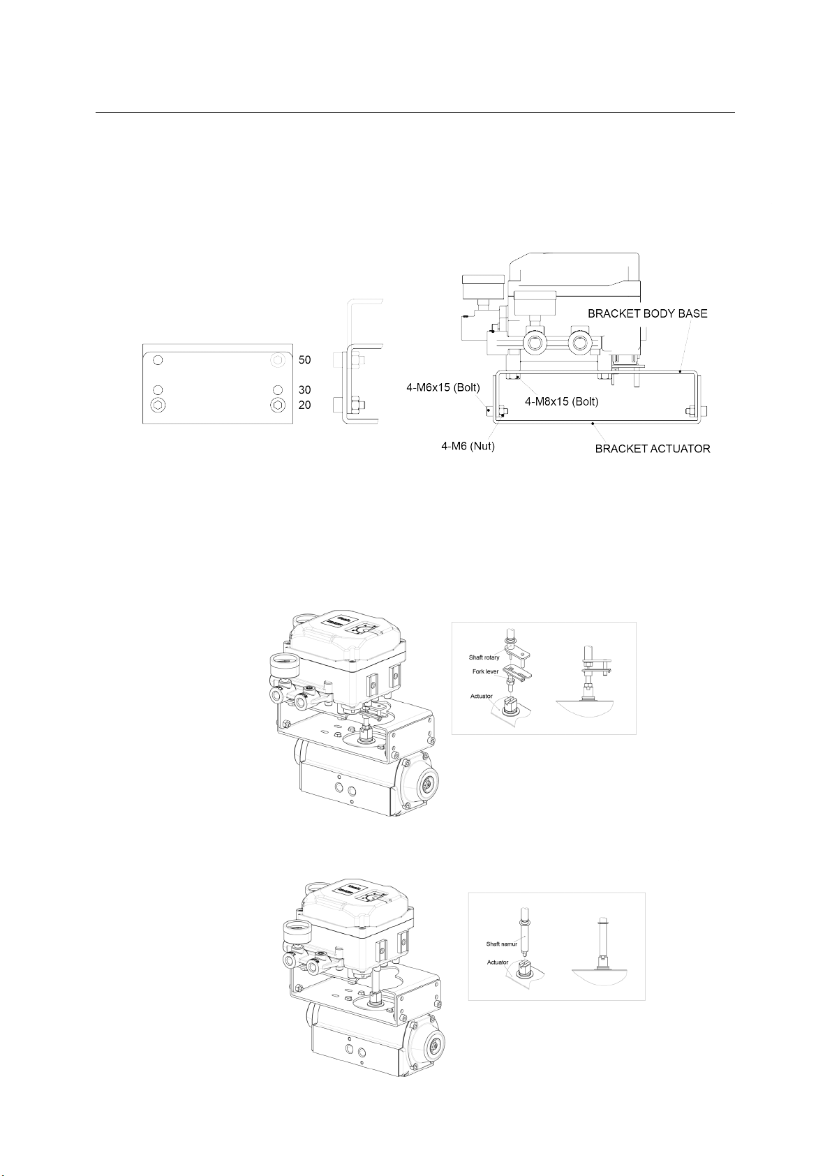
TS610L bracket Installation
Please consider the above two cautions, and make a suitable bracket for the actuator by
referring to the product dimension drawing and the installation example below.
<TS610L bracket installation example>
CAUTION
If correct installation, Feedback lever should not touch Stopper when the valve is Full
open/close.
If Feedback lever touches Stopper, please check the installation again.
<TS610L Feedback lever and Stopper>
14
P-P Positioner
TS610 Series
tissin
3.3 TS610R Rotary type
TS610R Rotary type includes the mounting brackets in the package box. Please install the
bracket by referring to the manual.
<TS610R bracket installation example>
Fork Leve type
Mount Fork lever to actuator as shown below.
NAMUR type
Mount Positioner’s shaft to Actuator stem as shown below.

15
P-P Positioner
TS610 Series
tissin
4 Air connection
4.1 Before the air connection
NOTICE
Please supply the dehumidified/dust removed clean air
The pneumatic ports must be equipped with a regulator to supply a constant pressure of
pneumatic pressure.
When the input pneumatic signal (0.02 to 0.1 MPa) increases, the pneumatic output of
OUT1 port increases.
4.2 TS610L air connection
<TS610L Single actuator> <TS610L Double actuator>
4.3 TS610L RA/DA settings
The product is set as RA at factory. If you want to change it to DA, please change the
OUT1/OUT2 piping and the direction of Span adjust unit.
<DA> <RA>
16
P-P Positioner
TS610 Series
tissin
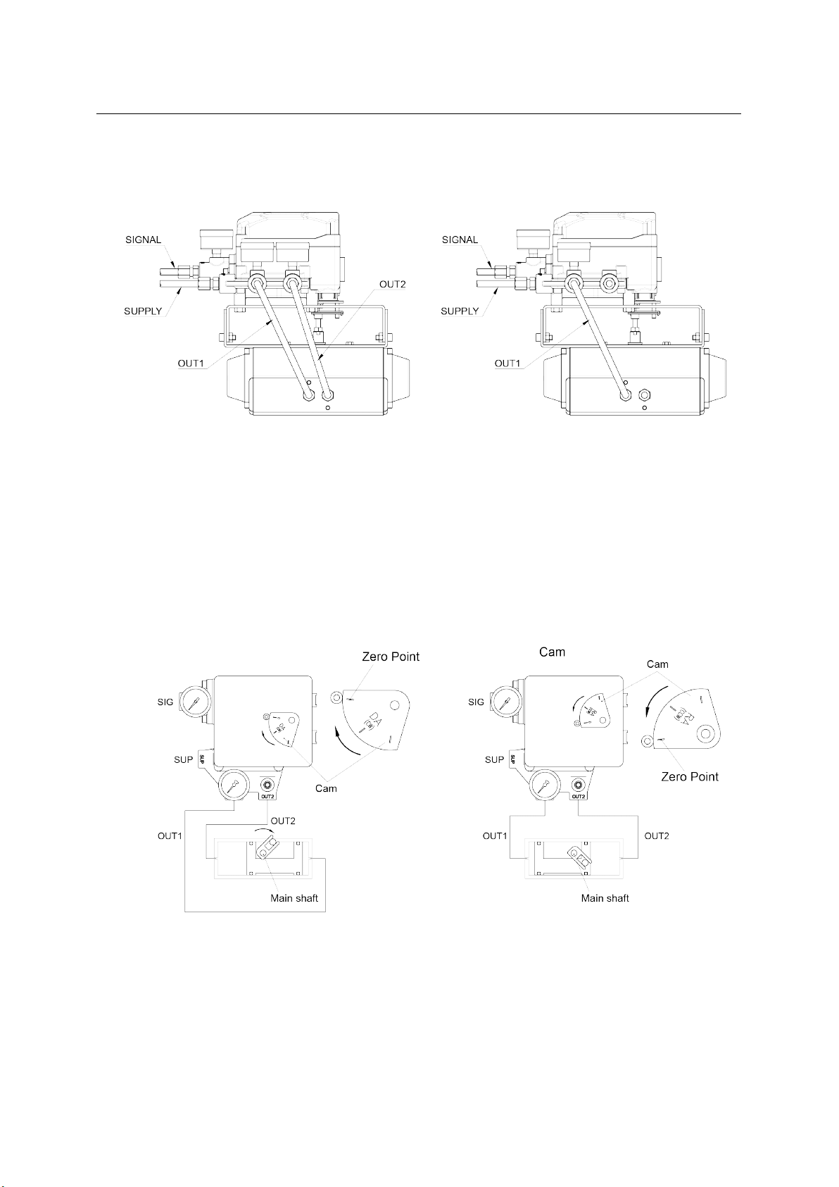
4.4 TS610R air connection
<TS610R Double type actuator > < TS610R Single type actuator >
4.5 TS610R RA/DA settings
The product is set as RA at factory. If you want to change it to DA, please change the
OUT1/OUT2 piping and turn CAM upside down to showing DA on CAM.
<DA > <RA>
17
P-P Positioner
TS610 Series
tissin
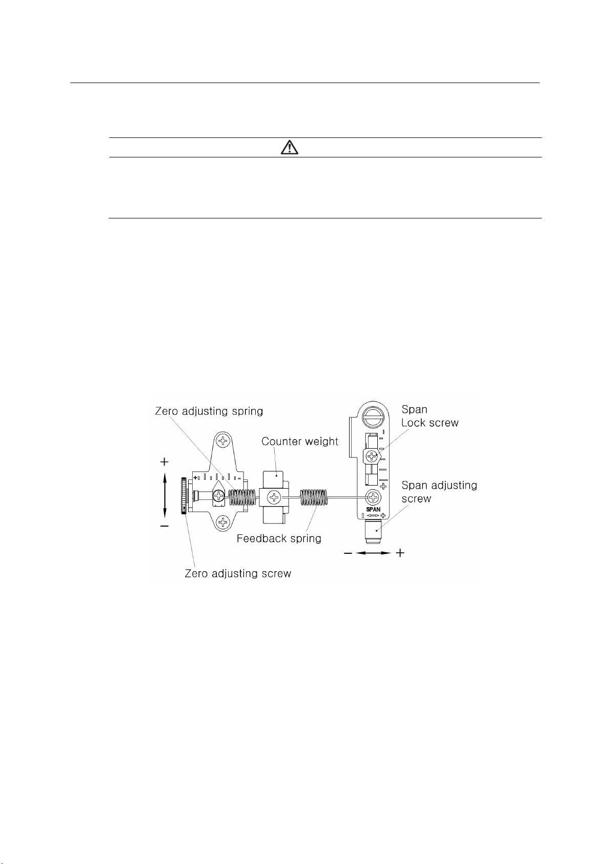
5 Adjustment
CAUTION
Zero and Span must be set correctly so product can be operated normally. If the setting is
not correct, impact on performance like linearity. So please set Zero and Span position
correctly.
Zero and Span adjustment
①Supply 0.02 MPa to Signal port, and adjust Zero adjust unit to make the valve 0%.
②Supply 0.1 MPa to Signal port, and adjust Span adjust unit to make the valve 100%.
③If adjust Span adjust unit, the valve’s 0% position you set in STEP 1 will be changed, so
please do STEP 1 again.
④Please repeat STEP 1~2 until find the valve’s Open/Close position correctly.
<Zero and Span unit>

18
P-P Positioner
TS610 Series
tissin
6 Troubleshooting
6.1 Common problems
Failure The valve is fully open regardless of the input signal
Causes
The hole of A / M switch of pilot valve is blocked by foreign matter
such as dust
Solution
As shown below, loosen the stopper screw and separate A / M switch
and clean the bottom of the hole with 0.2mm drill or wire and re-fitted
as original.
< A/M switch structure>
CAUTION
The sensitivity adjustment screw is set optimally at the factory, so do NOT adjust it.
6.2 Orifice Installation
Failure
When mounted on small size actuator (capacity less than 180cm3)
occurs hunting.
Causes
The pneumatic output of the positioner is too large compared to the
actuator chamber size.
Solution As shown below, please remove O-Ring at OUT1 and OUT2 at the
bottom of Pilot valve, and install Orifice to Pilot valve.
<Orifice installation example>

19
P-P Positioner
TS610 Series
tissin
6.3 Other problems and Solutions
☞
The positioner does not operate
Checklist Causes Corrective action
Reference
page
If it does not work by moving
the nozzle flapper
A/M switch is loose
Check to see if A/M
switch is connected
18
Nozzle clogged
Nozzle needs clean up
18
☞
The actuator works only with ON / OFF control but not intermediate control.
Checklist Causes Corrective action
Reference
page
Linear type, check span
mounting
Span is mounted upside
down
Turn the span body 15
Rotary type, check cam
mounting
Cam is mounted upside
down
Mount the cam
correctly
16
Check OUT1, OUT2 pipeline
OUT1 and OUT2 Pipelines
are connected in opposite
directions
Install pipeline correctly 15~16
☞
Hunting occurs
Checklist Causes Corrective action
Reference
page
Hunting period is too short
and the width is too large
(pressure gauge moves at
the same time of valve stem)
Actuator volume is too low Install the orifice on the
bottom part of the pilot 18
Hunting period is too long
and the width is too small
(Gauge markings move and
valve stem slowly follow)
High temperature high
pressure valve stem has a
large frictional force
1 Perform a necessary
action to minimize
resistance of actuator
or valve stem
2 Increase actuator size
N/A
☞
Linearity is too bad
Checklist Causes Corrective action
Reference
page
Zero and span setting zero and span setting is
incorrect
Resetting zero and
span 17
Check Input pressure is
constant
Input pressure is not
constant
Check the pressure
relief valve on supply
pressure is normal.
N/A
Verify lever installation Lever does not provide
optimum rotation angle
Adjust bracket and
place drawbar on valve
opening mark
12~13
☞
Hysteresis is too bad
Checklist Causes Corrective action
Reference
page
Check connection of lever
spring
Gap between the lever
Tighten the connection
to remove the gap
12~13

20
P-P Positioner
TS610 Series
tissin
Solutions for Control Valve System
Tissin Co.,Ltd.
201-1105, No 397, Seokcheon-ro,Ojeong-gu,
Bucheon-Si, Gyeonggi-do, Korea 14449
Tel : +82-32-624-4573,
Fax : +82-32-624-4574
www.tissin.co.kr
Table of contents
Other tissin Valve Positioner manuals


Popular Valve Positioner manuals by other brands

Aventics
Aventics R431004052 Service information

Avid Technology
Avid Technology SMARTCAL Installation and operation manual

Samson
Samson 4785 Mounting and operating instructions

Samson
Samson 3760 Mounting and operating instructions

CONFLOW
CONFLOW Power Genex PPR Series Installation and maintenance manual

Econ
Econ 3300 Series operating manual


