Kinetrol AP Maintenance and service guide

Issue
G
T.L.
NOV-20 Trading Estate Farnham Surrey England Doc. No.TD 106
Page 1 of 13
AR7187 ISSUE G
TD106 – 11/08:INDEX H\Drawing office docs. Master KF WI TD etc.\current TD sheet
masters
1. CONTENTS.
Page Section
1 1. Contents
2 2. Installation -
3
4 3. Description of Operation
5 4. Settings and Adjustments –
6
7 5. Maintenance and Troubleshooting
8-10 6. Angle Retransmit Option –
11-13 7. Spare Parts -
Title: Installation & Maintenance – AP Pneumatic Positioner
7.1 Exploded View
7.2 Spare Part Numbers
6.1 Installation
6.2 Change of Direction for rising signal
6.3 Zero and Range Adjustment
6.4 Change of Direction for rising signal (Discrete)
6.5 Change of Angle Retransmit direction without
changing positioner direction.
6.6 Angles of less than 0º to 90º
2.1 Direct Mounting Units onto Kinetrol Positioner
Actuators
2.2 Mounting of Discrete Positioners.
2.3 Air and Electrical Connections.
4.1 Change of Direction for rising signal (direct mounted)
4.2 Zero and Range Adjustment
4.3 Speed Control
4.4 Change of Direction for rising signal (Discrete)
KF 399

Issue
G
T.L.
NOV-20 Trading Estate Farnham Surrey England Doc. No.TD 106
Page 2 of 13
AR7187 ISSUE G
Note: For angle retransmit versions, refer to section 6.1
2.1.1 Move actuator vane to mid travel position, with its output square as shown in Figure 1. This is advisable to prevent
subsequent error in orientating positioner coupling. (This is not necessary with spring return actuators as there can be no
confusion with square orientation).
2.1.2 Remove positioner cover and undo the two M4 screws retaining the red angle scale plate and remove coupling as
shown in Figure 2.
2.1.3 Bolt the positioner body to the actuator in the orientation shown in Figure 1 taking care that the two O'rings are in
place to seal the ports to the actuator (place a small amount of grease onto the O'rings to keep them in place) and that the
actuator shaft is centred in the body.
2.1.4 Observe the direction that the cam moves with a rising signal and, if correct, place the coupling on the actuator
square with one hand whilst pulling back the mechanism with the other (refer to Figure 2). If the direction is not as required
then refer to section 4.1. If the actuator has been correctly positioned near mid-stroke, the cam follower will contact the
cam at approximately half way. Ensure that the coupling is pushed fully onto the actuator square and tighten the central
fixing screw which will have the effect of centralising the cam follower on cam. Refit the angle scale plate.
2.2 Mounting of Discrete Positioner.
The design and manufacture of the mount kit between the positoner and actuator is outside the scope of this document. It
is essential that the shaft of the actuator is well aligned with the positioner shaft and that the two are coupled together with
a minimum of backlash as this will reduce the performance of the positioner/actuator combination.
It is essential that the 90 degree travel of the actuator moves the positioner coupling through the correct 90 degrees of
travel. This can be achieved by either observing the position of the indicator on the lid or the position of the cam or internal
indicator with the lid removed.
2. INSTALLATION.
Positioners can be supplied direct-mounted, or ready to be direct-mounted, onto Kinetrol rotary actuators, or in stand-
alone (discrete) form for fitting via a mount kit to any 90 degree rotary or linear actuator. If the positioner is supplied
ready mounted on an actuator, sections 2.1 & 2.2 can be bypassed. Positioner-type Kinetrol actuators (ready for direct
mount of positioners) are available in models 050 to 140 inclusive.
2.1 Mounting of Direct Mounting Units onto Kinetrol Positioner-Type Actuators (without angle
retransmit)
Title: Installation & Maintenance – AP Pneumatic Positioner

Issue
G
T.L.
NOV-20 Trading Estate Farnham Surrey England Doc. No.TD 106
Page 3 of 13
AR7187 ISSUE G
2.3.1 Air Supply
Connect main air supply (pressure between 3.5 and 7 bar or 50 and 100psi) to the supply port indicated in figure 3. Also
connect signal air supply (pressure between 0.2 bar and 1 bar or 3 psi and 15 psi) to the inlet of the diaphragm housing.
It is important that the air is clean, dry and oil free. Quality class 6.4.4 (taken from ISO standard 8573.2001) is adequate.
This implies 5 micron max. Particle size, 3 deg. C dew point max. and 5mg per cubic metre max. oil content.
2.3.2 Angle Retransmit Option Supply.
The optional angle retransmit circuit is loop powered, requiring 8 to 30 volts to drive the 4-20mA current through it. The
current which passes is linearly in proportion to the shaft angle.
The cable entry has the option of a cable gland fitting or 4-way DIN plug. With the cable gland entry the wires are directly
connected to the internal Connector Block. An internal earth connection is provided if required. If the DIN plug option is
fitted then the internal connections have already been made as shown in Figure 3. An external earth connection is also
provided if this is required.
2.3.3 External Actuator Ports.
For positioners not fitted directly onto Kinetrol Positioner type Actuators, two external ports are provided for connecting
the positioner outlets to the actuator. The size of the ports is dependant on the positioner ordering code. These ports can
also be used for fitting pressure gauges if desired.
Title: Installation & Maintenance – AP Pneumatic Positioner
2.3 Pneumatic and Electrical Connections.

Issue
G
T.L.
NOV-20 Trading Estate Farnham Surrey England Doc. No. TD 106
Page 4 of 13
AR7187 ISSUE G
Title: Installation & Maintenance – AP Pneumatic Positioner
The AP Positioner works using the principal of a 'force balance' spool system with mechanical cam feedback. The air
input signal (normally 3-15psi) is applied to a diaphragm which produces a force on the force balance lever which is
proportional to the signal pressure. The resulting torque on the lever is balanced by the force produced from the
feedback spring which is also joined to the lever.
A proportional flow spool valve is the third element attached to the lever. This is positioned at its central closed position
when the lever is at the mid-stroke position which occurs when the actuator is at the desired angle. Several different
versions of this valve are available with different flow capacities designed to give optimum performance when fitted to
the range of Kinetrol actuators.
The feedback cam is retained by a coupling which, in the case of a Kinetrol direct mounted positioner, is held onto the
vane square by a collet. For discrete versions, the coupling is retained in bearings and connected by either a male
square or 'Namur' style connector.
The cam provides positional feedback via a unique four bar linkage which ensures a linear movement of the cam
follower whether the cam is set for clockwise or anticlockwise movement for a rising signal. The lower part of the
linkage is attached to the other end of the feedback spring which stretches the spring as the cam is rotated to produce
the feedback force mentioned earlier. The standard cam produces a linear characteristic, but alternative profiles are
available.
The common adjustments are split into zero and range. Both are achieved without the need for special tools and the
actual adjustments are made using finger pressure only.
Air passages in the main body are provided with the capability of many options with a minimum of changes. External
ports are provided on all models to allow for external connection to the actuator or for the fitting of pressure gauges if
desired. Three main air flow options are available (as detailed in the AP literature). The two lower flow rate options (AP
& MP) are affected by change of valve size and tapping size in the body. The largest flow rate option (HP) not only has
a larger valve but also a different port plate with 3/8 tapping and external combination silencer/snubbers.
The mounting options are accommodated by three different channel plate designs. The channel plate is the plate fitted
to the base of the unit. The smallest is dedicated to direct mounting on an 050 Actuator. The second is used for direct
mounting on Actuators 070 to 140. The third is used for discrete models having a Namur mounting hole pattern.
An optional angle retransmit can be fitted within the positioner body and additional options of I/P controller and limit
switch box can also be fitted allowing a wide range of switch options to be specified.
3. DESCRIPTION OF OPERATION.

Issue
G
T.L.
NOV-20 Trading Estate Farnham Surrey England Doc. No. TD 106
Page 5 of 13
AR7187 ISSUE G
Title: Installation & Maintenance – AP Pneumatic Positioner
4.1.1 Move the actuator to approximately mid-position to avoid problems in correct orientation later. This is obviously not
possible or necessary with spring return models because the position of the vane will be known. Reduce both main supply
and signal pressures to zero.
4.1.2 Remove positioner cover and undo the two M4 screws retaining the red angle scale plate and remove, as shown in
Figure 5. Loosen the central coupling screw sufficiently to draw the coupling off the actuator square.
4.1.3 Pull the two halves of the coupling apart sufficiently to allow the cam to be withdrawn from its location peg as shown
in Figure 6. Flip the cam over and push it back into the slot between the two coupling halves and locate it back on the peg.
4.1.4 If when the coupling was removed, the collet was left behind on the actuator square, remove the collet from the
square and push it into the lower half of the coupling ensuring that it locates in the semicircular 'pip'. Tighten the clamping
screw by two turns before placing it back on the actuator square such that the cam follower is approximately half way up
the rise of the cam and tighten the clamping screw. Replace the angle scale plate.
4.1.5 Undo the changeover block central screw and rotate it by a quarter turn and replace and tighten screw. For your
convenience, the changeover block is marked 'A' and 'C' which refers to 'anticlockwise' and 'clockwise' respectively.
Ensure the required letter is placed opposite the arrow marked on the top of the valve block.
4. SETTINGS AND ADJUSTMENTS.
The positioner will have been factory set to the requirements given in the ordering code ( i.e. the direction of rotation for
a rising pressure signal and the range and zero settings). However, if these settings need to be changed, the following
section describes the procedure for achieving this.
4.1 Change of Direction for Rising Signal (direct mounting units only).

Issue
G
T.L.
NOV-20 Trading Estate Farnham Surrey England Doc. No. TD 106
Page 6 of 13
AR7187 ISSUE G
Title: Installation & Maintenance – AP Pneumatic Positioner
4.2 Zero and Range Adjustment (refer to Figure 4).
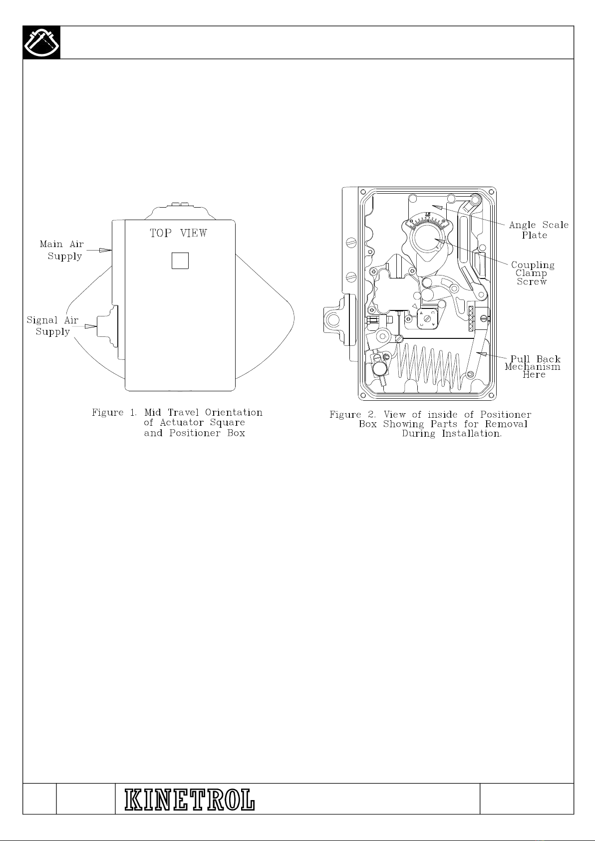
4.2.1 Move the actuator/positioner to the zero end of the stroke (i.e. when the cam follower is at the beginning of its rise).
This can be most easily achieved by pressurising the main air supply without any signal air pressure (spring return models
will already be at this position. Exhaust the supply air and move the internal indicator to indicate just below zero on the
angle scale.
4.2.2 Set the coarse zero by slackening the coupling screw by approximately half of a turn until the top part of the coupling
can be rotated by hand and rotate until the cam follower just starts to rise up the cam profile. Retighten the screw.
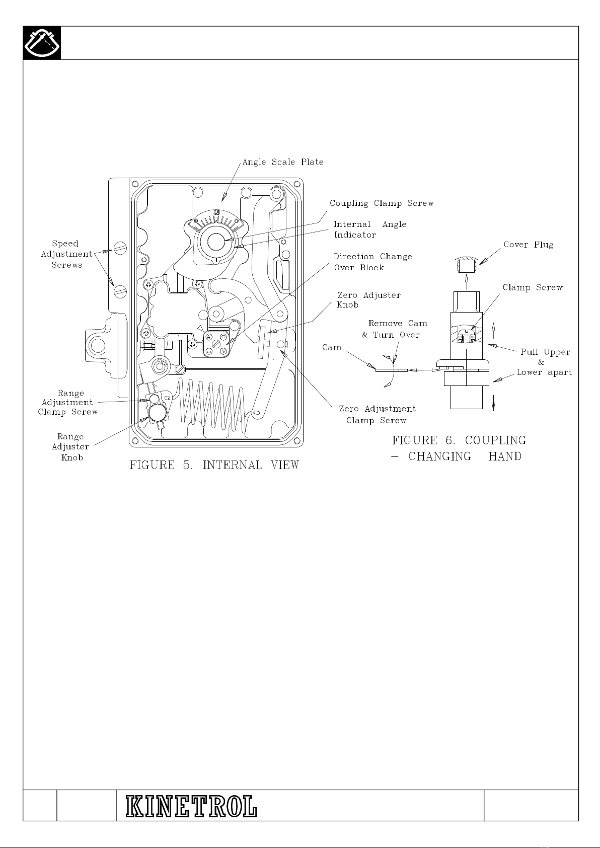
4.2.3 Turn on the main air supply and carefully increase the signal supply pressure to 3psi (0.2Bar). Slacken the fine zero
adjustment clamp screw and rotate zero adjuster using thumb pressure so that the actuator moves to indicate zero on the
internal indicator. Tighten clamp screw.
4.2.4 Increase the signal pressure to 15psi (1 Bar). Slacken the range adjuster clamp screw and rotate the adjuster knob
between thumb and forefinger until the actuator moves to the desired end stroke position (normally 90 degrees) as
indicated on the internal indicator. Re-tighten the clamp screw.
4.2.5 Reduce the signal air pressure again to 3 psi and check that the zero position has not changed.
4.3 Speed Control.
Maximum actuator speed can be regulated by the two following methods:
a.) Changing the valve spool/liner size. The valve size is normally specified at the point of ordering by the letters 'AP', 'MP'
or 'HP'. This method, however, not only effects the actuator speed but also effects the 'gain' and therefore control stability
of the unit and care must be taken not to specify a too high flow valve for a given size of actuator. Kinetrol Ltd has
recommendations (shown in the AP literature) for each size of the actuator
or
b.) adjustment of the built in flow restrictors (shown in Figure 4) is achieved using a screwdriver. There are two restrictors,
one for each direction of travel. Clockwise rotation, this will reduce the actuator speed. 'AP' and 'MP' size units with 1/8 or
1/4 ports are controlled in this way but 'HP' size units having 3/8 ports are fitted with external silencer/restrictors which are
adjusted using an allen key fitted down the centre of the adjuster.
4.4 Change of Direction for Rising Signal (discrete units).
4.4.1 Move actuator as in Section 4.1.1.
4.4.2 Remove positioner cover and undo the three M4 screws retaining the red retransmit plate, as shown in Figure 7.
Loosen the central coupling screw sufficiently to pull the coupling complete with the retransmit assembly off the actuator
connection.
4.4.3 Remove the internal indicator from the coupling and withdraw the coupling from the retransmit plate.
4.4.4 Pull the two halves of the coupling apart sufficiently to allow the cam to be withdrawn from its location peg. Flip the
cam over and push it back into the slot between the two coupling halves and locate it back on the peg.
4.4.5 Refit the coupling to the retransmit plate and slide the internal indicator over the top of the coupling.
4.4.6 If when the coupling was removed, the collet was left behind on the actuator connection, remove the collet from the
connection and push it into the lower half of the coupling ensuring that it locates in the semicircular 'pip' and tighten the
clamping screw by two turns. Place the coupling and retransmit plate back on the actuator connection such that the cam
follower is approximately half way up the rise of the cam and pull back the spring lever with the other hand and tighten the
coupling clamping screw. Re-tighten the retransmit plate retaining screws.
4.4.7 The internal changeover block is not effective with a discrete positioner. The changeover of the airflow path is
achieved by swapping over the external connections. It may also be preferred to turn the positioner through 180 degrees
to simplify the external pipe runs.
4.4.8 The adjustment of zero and range is completed as in section 4.2.

Issue
G
T.L.
NOV-20 Trading Estate Farnham Surrey England Doc. No. TD 106
Page 7 of 13
AR7187 ISSUE G
Title: Installation & Maintenance – AP Pneumatic Positioner
TABLE 1. Troubleshooting Guide
Failure to move when signal air and mains air is applied
- Check mains air pressure is sufficient to produce enough torque from actuator
- Check signal pressure using pressure gauge in gauge port or check that the force balance lever is being pushed by
the input diaphragm with the lid removed
- Has the coupling been positioned at the correct angular position on the actuator?
- Has the changeover block been set correctly for the direction of rotation (direct mounted units) or the external port
connections been fitted the correct way around (discrete units)?
- Is the air quality poor, causing the spool to jam? This can be checked by manually moving the spool carefully by
hand with the lid removed.
- Is the actuator or whatever it is connected to jammed? This can be checked by again moving the force balance lever
manually to check if the actuator responds (air will normally be heard hissing into the actuator when this is done).
Actuator moves too slowly upscale or down scale:
- Is the mains air pressure too low for the load being moved or the actuator too small?
- Have one or both flow adjuster screws been screwed in too far?
- Is the air contaminated causing the spool movement to become sluggish?
- Is the actuator volume too large for the spool flow rate chosen?
Lack of sensitivity:
- Is the spool sticky, caused by a contaminated air supply?
- Does the actuator exhibit poor stick slip qualities? This may be especially true if it is not Kinetrol and will normally be
seen also as a jerky movement.
Excessive Hysteresis:
- Has the inside of the positioner box become contaminated causing the force balance mechanism bearings to
become sticky?
- Is the actuator load excessive causing it to struggle to achieve position?
Overshoot/Instability:
- Is the spool valve chosen too large for the size of the actuator?
- Is the inertia loading too great for the size of actuator chosen? Refer to Kinetrol for allowable limits.
- Have the snubbers been used to slow the load down?
5. MAINTENANCE AND TROUBLESHOOTING.
The AP positioner is designed for a long life with very little maintenance required if it is supplied with clean, dry oil free air,
as recommended in section 2.3.
When the positioner lid is removed, take care not to remove all grease from the lid/coupling seal. If it does need
replenishing then ensure that a synthetic grease is used as a mineral oil grease will adversely affect this seal.
If, however, any of the parts do need replacement because of adverse conditions, then refer to Kinetrol Ltd for spare parts
together with any instructions for replacing and resetting.
The following trouble shooting guide should help in the unlikely event of a problem with the performance of the unit. If
problems persist, contact your local Kinetrol distributor or Kinetrol Ltd for further advice.

Issue
G
T.L.
NOV-20 Trading Estate Farnham Surrey England Doc. No. TD 106
Page 8 of 13
AR7187 ISSUE G
Title: Installation & Maintenance – AP Pneumatic Positioner
6.1.1 Move actuator vane to mid travel position, with its output square as shown in Figure 1. This is advisable to prevent
subsequent error in orientating positioner coupling. (This is not necessary with spring return actuators as there can be no
confusion with square orientation).
6.1.2 Remove positioner cover and unscrew the three M4 screws retaining the red retransmit plate, release the two wires
on the terminal block connected to the DIN plug (if fitted), as shown in Figure 7, and carefully remove coupling and
retransmit assembly as one unit.
6.1.3 Bolt the positioner body to the actuator in the orientation shown in Figure 1 taking care that the two O'rings are in
place to seal the ports to the actuator (place a small amount of grease on to the O'rings to keep them in place) and that
the actuator shaft is centred in the hole in the body.
6.1.4 Observe the direction that the cam moves with a rising signal and that the retransmit strap is fitted to the correct slot
in the lower coupling as marked (C & A for clockwise and anticlockwise respectively). If the direction is not as required
then refer to section 6.2. If correct, place the coupling and retransmit assembly on the actuator square with one hand
whilst pulling back the mechanism and two DIN plug wires with the other (refer to Figure 6). If the actuator has been
correctly positioned near mid-stroke, the cam follower will contact the cam as approximately half way.
6.1.5 Ensure that the coupling is pushed fully on to the actuator square and tighten the central fixing screw which will
have the effect of centralising the cam follower on the cam track. Retighten the three angle retransmit retaining screws
and refit the two DIN plug wires (if fitted).
6.2 Change of Direction for Rising Signal (direct mounting units only).
6.2.1 Move the actuator to approximately mid-position to avoid problems in correct orientation later. This is obviously not
possible or necessary with spring return models because the position of the vane will be known. Reduce both main
supply and signal pressures to zero.
6.2.2 Remove positioner cover and undo the three M4 screws retaining the red retransmit plate, release the two wires on
the terminal block connected to the DIN plug (if fitted), as shown in figure 7. Loosen the central coupling screw sufficiently
to carefully pull the coupling complete with the retransmit assembly off the actuator square.
6.2.3 Release the potentiometer strap from the slot in the lower coupling, as shown in figure 8, remove the internal
indicator from the coupling and withdraw the coupling from the retransmit plate.
6. ANGLE RETRANSMIT OPTION.

Issue
G
T.L.
NOV-20 Trading Estate Farnham Surrey England Doc. No. TD 106
Page 9 of 13
AR7187 ISSUE G
Title: Installation & Maintenance – AP Pneumatic Positioner
6.2.4 Pull the two halves of the coupling apart sufficiently to allow the cam to be withdrawn from its location peg. Flip the
cam over and push it back into the slot between the two coupling halves and locate it back on the peg.
6.2.5 Refit the coupling to the retransmit plate, slide the internal indicator over the top of the coupling and refit the
potentiometer strap into one of the two marked slots of the lower coupling (marked 'A' and 'C' for anticlockwise and
clockwise movement respectively).
6.2.6 If when the coupling was removed, the collet was left behind on the actuator square, remove the collet from the
square and push it into the lower half of the coupling ensuring that it locates in the semicircular 'pip' and tighten the
clamping screw by two turns. Place the coupling and retransmit assembly back on the actuator square so that the cam
follower is approximately half way up the rise of the cam whilst holding back the two retransmit wires and pull back the
spring lever with the other hand and tighten the coupling clamping screw. Re-tighten the retransmit plate retaining screws
and refit the retransmit wires to the terminal block.
6.2.7 To ensure a rise in retransmit signal with rising input pressure signal, the top and bottom wires on the feedback
potentiometer must be reversed in the connector located on the circuit. The central wire does not change.
6.2.8 Undo the changeover block central screw and rotate it by a quarter turn and replace and tighten screw. The
changeover block is marked 'A' and 'C' which refers to 'anti-clockwise' and 'clockwise' respectively. Ensure the required
letter is placed opposite the arrow marked on the top of the valve block.
6.3 Zero and Range Adjustment (refer to Figure 7).
Setting of the mechanical zero and range for the positioner with an angle retransmit is the same as described in section
4.2. The retransmit circuit must also be set for zero and range which is described below.
6.3.1 Set the circuit zero adjustment to the central position and connect a 4-20ma electrical source via the DIN plug or
terminal block.
6.3.2 Set the positioner to zero degrees or the input pressure to 3 psi (0.2 Bar)
6.3.3 Slacken the two screws which clamp the potentiometer to the retransmit plate but do not remove. Rotate the
potentiometer slowly using finger pressure until the electrical display shows 4ma.
6.3.4 Increase the air signal pressure to 15 psi (1 Bar) to set the positioner at 90 degrees. Adjust the Span potentiometer
to read 20ma.
6.3.5 Repeat steps 6.3.2 to 6.3.4 until the desired readings are obtained at both ends of the stroke. The fine zero
potentiometer can be used to obtain a more precise reading at the zero position.
6.3.6 Tighten the two potentiometer clamp screws.
6.4 Change of Direction for Rising Signal (discrete units).
6.4.1 Move actuator as in Section 6.2.1.
6.4.2 Remove positioner cover and undo the three M4 screws retaining the red retransmit plate, release the two wires on
the terminal block connected to the DIN plug (if fitted), as shown in figure 7. Loosen the central coupling screw sufficiently
to pull the coupling complete with the retransmit assembly off the actuator connection.
6.4.3 Release the potentiometer strap from the slot in the lower coupling, as shown in Figure 8, remove the internal
indicator from the coupling and withdraw the coupling from the retransmit plate.
6.4.4 Pull the two halves of the coupling apart sufficiently to allow the cam to be withdrawn from its location peg. Flip the
cam over and push it back into the slot between the two coupling halves and locate it back on the peg.
6.4.5 Refit the coupling to the retransmit plate and slide the internal indicator over the top of the coupling and refit the
potentiometer strap into one of the two marked slots of the lower coupling (marked 'A' and 'C' for anticlockwise and
clockwise movement respectively).

Issue
G
T.L.
NOV-20 Trading Estate Farnham Surrey England Doc. No. TD106
Page 10 of 13
AR7187 ISSUE G
Title: Installation & Maintenance – AP Pneumatic Positioner
6.4.6 If when the coupling was removed, the collet was left behind on the actuator connection, remove the collet from
the connection and push it into the lower half of the coupling ensuring that it locates in the semicircular 'pip' and
tighten the clamping screw by two turns. Place the coupling and retransmit plate back on the actuator connection so
that the cam follower is approximately half way up the rise of the cam whilst holding back the two retransmit wires
and pull back the spring lever with the other hand and tighten the coupling clamping screw. Re-tighten the retransmit
plate retaining screws and refit the retransmit wires to the terminal block.
6.4.7 The internal changeover block is not effective with a discrete positioner. The changeover of the air flow path is
achieved by swapping over the external connections. It may also be preferred to turn the positioner through 180
degrees to simplify the external pipe runs.
6.4.8 The adjustment of zero and range is completed as in section 6.3.
6.5 Change of Angle Retransmit Direction Without Changing Positioner Direction
If a non-standard rise in retransmit signal is required without a change in positioner direction, then this can be
achieved by the following procedure.
6.5.1 Swap the top and bottom wires on the angle retransmit circuit which connect to the potentiometer.
6.5.2 Repeat the zero and range set-up procedure described in section 6.3.
6.6 Angle Retransmit for angles of less than 0º to 90º
If the positioner is fitted with a non-standard cam with a special characteristic, it may be necessary to move the
jumper (located under the angle retransmit circuit cover) to link the pins in order to achieve the correct feedback
signal range.

Issue
G
T.L.
NOV-20 Trading Estate Farnham Surrey England Doc. No. TD 106
Page 11 of 13
AR7187 ISSUE G
Title: Installation & Maintenance – AP Pneumatic Positioner

Issue
G
T.L.
NOV-20 Trading Estate Farnham Surrey England Doc. No. TD 106
Page 12 of 13
AR7187 ISSUE G
Title: Installation & Maintenance – AP Pneumatic Positioner
ITEM
NO. DESCRIPTION
SPARES PART NUMBER
AP
MP
HP
050
070
090
10 / 12 / 14
16/18/20/30
1
Cover Assembly - standard*
SP1200
SP1200
SP1200
SP1200
SP1200
Cover Assembly – for switch box*
SP1201
SP1201
SP1201
SP1201
SP1201
2
Cover Seal & Grease - NBR
SP1202
SP1202
SP1202
SP1202
SP1202
Cover Seal & Grease - Viton
SPV1202
SPV1202
SPV1202
SPV1202
SPV1202
3
Indicator Assembly
SP703
SP703
SP703
SP703
SP703
4
Monitor Kit ACW
SP978
SP978
SP978
SP978
SP978
Monitor Kit CW
SP979
SP979
SP979
SP979
SP979
5
Cover screws
SP1203
SP1203
SP1203
SP1203
SP1203
6
'O' Ring (Lid) - NBR
SP1204
SP1204
SP1204
SP1204
SP1204
'O' Ring (Lid) - Viton
SPV1204
SPV1204
SPV1204
SPV1204
SPV1204
7
Switch Box Spacer Plate & 'O' Rings
SP1205
SP1205
SP1205
SP1205
SP1205
8
Postioner Body*
SP1206
SP1207
SP1207
SP1207
SP1207
9
Screws (Pos/Act. Interface)*
SP732
SP733
SP733
SP733
-
10 'O' Rings (Pos/Act. Interface) SP734 SP735 SP735 SP735 -
11
Cam/Spring Lever Assembly
SP1208
SP1208
SP1208
SP1208
SP1208
12
Cam Follower
SP1209
SP1209
SP1209
SP1209
SP1209
13
Short Link
SP1210
SP1210
SP1210
SP1210
SP1210
14
Feedback Spring
SP716
SP716
SP716
SP716
SP716
15
Range Adjuster Assembly
SP1211
SP1211
SP1211
SP1211
SP1211
16
Force Balance Lever Assembly
SP1212
SP1212
SP1212
SP1212
SP1212
17
Washer & Circlip
SP1213
SP1213
SP1213
SP1213
SP1213
18
Diaphragm Cover
SP720
SP720
SP720
SP720
SP720
19
Diaphragm Assembly - Polyurethane SP1214 SP1214 SP1214 SP1214 SP1214
Diaphragm Assembly - Viton
SPV1214
SPV1214
SPV1214
SPV1214
SPV1214
20
Screws & Washers (Diaphragm Cover)
SP721
SP721
SP721
SP721
SP721
21
Port Plate*
SP1215
SP1216
SP1216
SP1216
SP1217
22
Screws (Port Plate)
SP1218
SP1218
SP1218
SP1218
SP1219
23
Exhaust Regulators
SP1220
SP1220
SP1220
SP1220
SP1221
24
Port Plate Gasket
SP1222
SP1222
SP1222
SP1222
SP1223
25
Silencer & Silencer Clamp
SP1224
SP1224
SP1224
SP1224
SP1221
26
Inlet Filter
SP1225
SP1225
SP1225
SP1225
SP1226
27
Valve Block, Bobbin & Force Balance Lever
SP1231
SP1231
SP1231
SP1231
SP1231
28
Valve Block Gasket - NBR
SP1240
SP1240
SP1240
SP1240
SP1240
Valve Block Gasket - Viton
SPV1240
SPV1240
SPV1240
SPV1240
SPV1240
29
Screws & Washers (Valve Block)
SP1241
SP1241
SP1241
SP1241
SP1241
30
Changeover Block
SP1242
SP1242
SP1242
SP1242
SP1242
31
Changeover Gasket - NBR
SP1243
SP1243
SP1243
SP1243
SP1243
Changeover Gasket - Viton
SPV1243
SPV1243
SPV1243
SPV1243
SPV1243
32
Screw & Washer (Changeover Block)
SP1244
SP1244
SP1244
SP1244
SP1244
33
Channel Plate - Standard*
SP1245
SP1246
SP1246
SP1246
SP1247
Channel Plate - Discrete*
SP1247
SP1247
SP1247
SP1247
SP1247
34
Channel Plate Gasket
SP1248
SP1248
SP1248
SP1248
SP1248
35
Screws (Channel Plate)
SP1249
SP1249
SP1249
SP1249
SP1249
36
Bearing Bush & 'O' Ring (Discrete)
SP1250
SP1250
SP1250
SP1250
SP1250
37
Angle Scale & Screws
SP1251
SP1251
SP1251
SP1251
SP1251
38
Retransmit Plate, Bush and Screws (Discrete)
SP1252
SP1252
SP1252
SP1252
SP1252

Issue
G
T.L.
NOV-20 Trading Estate Farnham Surrey England Doc. No.TD 106
Page 13 of 13
AR7187 ISSUE G
Title: Installation & Maintenance – AP Pneumatic Positioner
ITEM
NO.
DESCRIPTION SPARES PART NUMBER
AP MP HP
050
070
090
10 / 12 / 14
16/18/20/30
39
Coupling
SP1253
SP1254
SP1254
SP1254
SP1253
Discrete Coupling
SP1253
SP1253
SP1253
SP1253
SP1253
40
Discrete Drive Adaptor - Kinetrol
SP1601
SP1601
SP1601
SP1601
SP1601
Discrete Drive Adaptor - Namur
SP1256
SP1256
SP1256
SP1256
SP1256
41
3/8 External Port Adaptor*
-
-
-
-
SP1257
42
'O' Ring (Port Adaptor)
-
-
-
-
SP1258
43
Blanking Plug*
SP1259
SP1259
SP1259
SP1259
SP1259
44
Valve Block Cap
-
-
-
-
SP1260
45
Valve Block Cap Gasket
-
-
-
-
SP1261
46
Valve Block Cap Screws & Washers
-
-
-
-
SP1262
47
Cam (See catalogue)
-
-
-
-
-
48
Angle Retransmit Kit (See catalogue)
-
-
-
-
-
49
Potentiometer
SP1263
SP1263
SP1263
SP1263
SP1263
50
Potentiometer Drive Strap
SP1264
SP1264
SP1264
SP1264
SP1264
51
Screw (Strap)
SP1265
SP1265
SP1265
SP1265
SP1265
52
Quadrant Wheel
SP1266
SP1266
SP1266
SP1266
SP1266
53
Torsion Spring
SP1267
SP1267
SP1267
SP1267
SP1267
54
Bush (Torsion Spring)
SP1268
SP1268
SP1268
SP1268
SP1268
55
Circuit
SP1269
SP1269
SP1269
SP1269
SP1269
56
Terminal Block
SP1270
SP1270
SP1270
SP1270
SP1270
57
Nuts (Angle Retransmit Plate)
SP1271
SP1271
SP1271
SP1271
SP1271
58
Din Plug*
SP1272
SP1272
SP1272
SP1272
SP1272
-
Recommended Spares Kit (NBR)
SP1280
SP1280
SP1280
SP1280
SP1280
-
Recommended Spares Kit (Viton)
SPV1280
SPV1280
SPV1280
SPV1280
SPV1280
This manual suits for next models
4
Table of contents
Other Kinetrol Valve Positioner manuals
Popular Valve Positioner manuals by other brands

Siemens
Siemens 6DR50 Series operating instructions

Ytc
Ytc YT-2700 Series user manual

Montana Instruments
Montana Instruments The Rook CryoAdvance 50 user manual

Samson
Samson Type 3766 Mounting and operating instructions

STI
STI FasTrak Installation and maintenance instruction manual

Baker Hughes
Baker Hughes Becker Series instruction manual