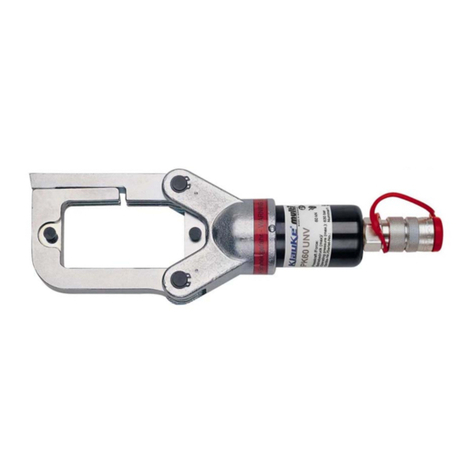
METU PNZ User manual

GEBRAUCHSANWEISUNG PNEUMATISCHE NOCKENZANGE
PNEUMATIC NOTCHING TOOL OPERATIONS´ MANUAL
MODE D´EMPLOI DE LA PINCE A ERGOTS PNEUMATIQUE
PNZ V. 2017-07
Copyright © 2017 METU Meinig AG. Alle Rechte vorbehalten. METU, METU-FORM und die entsprechenden
Logos sind eingetragene Marken ® der METU Meinig AG. Wir behalten uns das Recht vor, bei allen Produkten
ohne Vorankündigung Änderungen hinsichtlich Konstruktion, Ausstattung, Material, technische Daten
äußerem Erscheinungsbild, usw. vorzunehmen.
Copyright © 2017 METU Meinig AG. All rights reserved. METU, METU-FORM and the corresponding logos
are registered trademarks ® of the company METU Meinig AG. We reserve the right by all products to bring
modifications regarding their construction, equipment, material, technical characteristics, appearance, etc.
without prior notification.
Copyright © 2017 METU Meinig AG. Tous droits réservés. METU, METU-FORM et les logos correspondants sont
des marques déposées ® de la société METU Meinig AG. Nous nous réservons le droit de modifier sans préavis
tous les articles tant en ce qui concerne leur construction, équipement, matériel, caractéristiques techniques
ou encore leur apparence.

2017-07 Gebrauchsanweisung PNZ Nockenzange / PNZ Operations Manual / Mode d´emploi de la PNZ 1
KARTONINHALT
BOX CONTENTS
CONTENUE DU CARTON
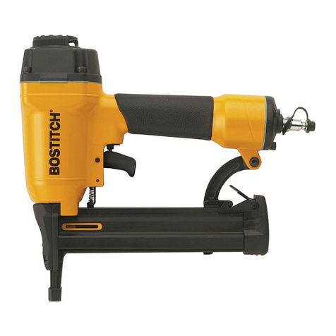
1 Pneumatische Nockenzange (PNZ)
Pneumatic Notching Tool (PNZ)
Pince a ergots pneumatique (PNZ)
1 Kopf und Stanzhebel
Head and punching lever
Tête avec levier de poinçonnage
1 Enddeckel
End cover
Couvercle
2 Anschläge 7 mm
Stopping faces 7 mm
Butoirs 7 mm
2 Anschläge 9 mm
Stopping faces 9 mm
Butoirs 9 mm
1 Gestanztes Musterblech
Sheet metal sample with notches
Echantillon de tôle avec ergots
1 Innensechskantschlüssel kurz M6
Hexagon socket screw key m6
Cle male coudée pour vis a six pans creux M6
1 Innensechskantschlussel kurz M4
Hexagon socket screw key m4
Clé male coudée pour vis a six pans creux M4
1 Innensechskantschlüssel kurz M2,5
Hexagon socket screw key m2,5
Clé male coudée pour vis a six pans creux M2,5
1 Hakenschlüssel 40-42
Sickle Spanner 40-42
Clé à ergot 40-42
1 Ölspritze
Oil syringe
Seringue à huile
1 Ölflasche
Oil flask
Flacon pour huile
1 Winkelanschlußstück für Luft mit Dichtung
Angle connection for pressurized air with sealer
Connection pour air pressurisé en forme de coude avec joint
1 Schlauchverbindung für 7 mm Ø
Union joint
Raccord pour tuyaux
1 Schlauchverbindung für 12 mm Ø
Union joint
Raccord pour tuyaux
1 Gebrauchsanweisung
Owner’s manual
Manuel d’instructions

2017-07 Gebrauchsanweisung PNZ Nockenzange / PNZ Operations Manual / Mode d´emploi de la PNZ 2
GEBRAUCHSANWEISUNG PNEUMATISCHE NOCKENZANGE
WICHTIGE INFORMATIONEN
Die Informationen in dieser Gebrauchsanweisung wurden sorgfältig ermittelt. Eine Garantie für Vollständig-
keit und Richtigkeit kann allerdings nicht übernommen werden. Ein Haftung aufgrund unvollständiger bzw.
ungenauer Informationen ist deshalb ausgeschlossen. Wir behalten uns das Recht vor, bei allen Produkten
ohne Vorankündigung Änderungen vorzunehmen.
Wir empfehlen beim Umgang mit unseren Produkten grundsätzlich Schutzhandschuhe zu tragen.
ZUM GERÄT
Mit der pneumatisch-hydraulischen Nockenzange können Nocken in die Rohrwand eingedrückt werden.
Das Gerät kann für alle Rohrflanschgrößen (AF und BF 20 - 160) verwendet werden.
Das Gehäuse besteht aus einem hochfesten Kunststoff mit eingespritzter Leichtmetallverstärkung
und eingeschraubter Kolbenführung. Das Pneumatikzylinderrohr besteht aus einem Stahlrohr. Bei
Verschleißerscheinungen brauchen lediglich die entsprechenden Einzelteile ausgewechselt werden.
Diese sind leicht zugänglich, was sich kostengünstig auf die Reparatur auswirkt.
Bei horizontaler Anwendung befindet sich der Schwerpunkt des Werkzeugs direkt unter der Hand und
gestattet somit ein ermüdungsfreies Arbeiten. Durch die sehr kompakte Kunststoffbauweise und die
Ausbildung des Hydraulikteils als Griff, liegt die Nockenzange sehr gut in der Hand.
Das Gerät ist mit einem Sicherheitsventil ausgerüstet. Bei einem Arbeitsdruck von 6 bis 6,5 bar öffnet sich
das Ventil automatisch und schließt sich wieder bei Reduzierung des Druckes.
Der stabile Schneidkopf aus Stahl läßt die Sicht auf die Schneidstelle frei. Der Hebelmechanismus ist direkt
über einen Gewindebolzen mit dem Hydraulikkolben verbunden.
Durch ein besonders günstiges Verhältnis vom Pneumatik- zum Hydraulikkolben, erreicht dieser eine
Zugkraft von 15 kN bei 6 bar. Diese Kraft die am Zugbolzen wirkt, wird durch den Hebelmechanismus
nochmals übersetzt und führt zu einer Schneidkraft an den beiden Schneiden von 18 kN. Dies erlaubt
wiederum eine max. Blechdicke von: Stahl verz.: 1,5 mm; V2A und V4A: 1,2 mm.
Die Messer sind gehärtet und austauschbar. Sie haben bei normalem Gebrauch eine sehr lange Lebens-
dauer. Das Obermesser kann nachgeschliffen werden, das Untermesser kann vierfach gedreht werden.
Seitliche Anschlagflächen sorgen durch ihren großen Abstand für das winkelrechte Ansetzen der Zange und
den richtigen Abstand des Nockens zum Blechrand. Diese Anschläge müssen je nach Randabstand der
Nocken ausgetauscht werden.

2017-07 Gebrauchsanweisung PNZ Nockenzange / PNZ Operations Manual / Mode d´emploi de la PNZ 3
GEBRAUCHSANWEISUNG PNEUMATISCHE NOCKENZANGE
Die Nockenhöhe muß der Blechdicke angepaßt werden. Dies geschieht durch Verstellen der M8 Schraube
am Zugbolzen.
Das Blech darf keinesfalls weiter als 1 mal Blechdicke durchgestanzt werden, da dies sonst zu einer
schlechten Auflagefläche des Spreizrandes führt.
Wir bitten Sie vor Gebrauch des Gerätes die Gebrauchsanweisung genau durchzulesen, damit eine ein-
wandfreie Verarbeitung gewährleistet ist.
GEBRAUCHSANWEISUNG
Anschluß der Pneumatischen Nockenzange:
Das Gerät aus der Verpackung nehmen und an die Druckluft anschließen. Um die Lebensdauer
des Gerätes zu erhöhen, empfiehlt es sich, wie bei allen druckluftbetriebenen Werkzeugen, eine
Druckluftwartungseinheit (Filter und Nebelöler) in die Druckluftleitung einzubauen. Das Gerät darf mit einem
maximalen Druck von 6,5 bar betrieben werden. Wird mit höherem Druck gearbeitet führt dies zum Defekt
des Gerätes. Bei Leitungsdrücken über 6 bar muß ein Druckminderer eingebaut werden, welcher auf einen
maximalen Druck von 6,5 bar einzustellen ist.
Arbeiten mit dem Gerät:
Zuerst sollten Sie sich davon überzeugen, dass die richtigen Anschlagplatinen im Gerät eingesetzt sind.
Sollte dies nicht der Fall sein, so lösen Sie die beiden Schrauben mit denen die Anschlagplatinen am
Schneidkopf befestigt sind.
Entnehmen Sie die richtigen Anschlagplatinen aus dem Magazin im Enddeckel und schrauben sie diese am
Schneidkopf fest.
Die ausgetauschten Anschlagplatinen sollten gleich wieder am Enddeckel befestigt werden, da sie sonst
leicht verloren gehen könnten.
Hier die richtigen Anschläge für den entsprechenden Rohrflansch:
Rohrflansch Rohr-Ø Nockenrandabstand
AF und BF 20 - 45 200 - 450 mm 7 mm
AF und BF 50 - 90 500 - 900 mm 9 mm
AF und BF 100 - 160 1000 - 1600 mm 15 mm (wird ohne Anschlagplatine erreicht)
Der Nockenrandabstand von 15 mm
benötigt keine Anschlagplatinen!

2017-07 Gebrauchsanweisung PNZ Nockenzange / PNZ Operations Manual / Mode d´emploi de la PNZ 4
GEBRAUCHSANWEISUNG PNEUMATISCHE NOCKENZANGE
Jetzt nehmen Sie ein Stück Abfallblech zur Hand, um einen Probenocken einzudrücken. Die Dicke des
Bleches muß der Dicke der später zu bearbeitenden Rohrwand entsprechen. Nun die Nockenzange
ansetzen und darauf achten, dass die linke und die rechte Anschlagplatine an der Blechkante anliegen.
Nun Drücker (36) nach hinten ziehen. Das Obermesser bewegt sich nach unten und die Nocke wird
eingedrückt. Nachdem Sie den Auslöser loslassen, schwenkt das Obermesser in seine Ausgangslage
zurück.
Achtung: Achten Sie darauf, dass Sie mit der freien Hand während des Auslösevorgangs genügend
Abstand zum Schneidkopf und den Schneidmessern halten. Verletzungsgefahr!
Prüfen Sie nun die Tiefe des eingedrückten Probenockens; er sollte genau 1 mal Blechdicke betragen
(siehe Skizze). Ist der Nocken tiefer eingedrückt, so schneidet der Spreizrand den Nocken seitlich ein.
Ist der Nocken zu wenig tief eingestanzt, so besteht die Gefahr, daß der Flanschring unter Belastung über
den Nocken rutscht.
A
B
C
D
Rohr innen
Inside the duct
Intérieur de la gaine
A. AF und BF 20-45 = 7 mm
AF und BF 50-90 = 9 mm
AF und BF 100-160 = 15 mm
B. ca. 4 mal die Blechdicke
C. Blechdicke
D. 1 mal Blechdicke
Um die Schnitttiefe genau einzustellen, befindet sich vorne am Schneidkopf eine M8 Inbusschraube.
Drehen Sie die Schraube im Uhrzeigersinn rechts, wird die Schnitttiefe erhöht, drehen Sie im Uhrzeigersinn
links, wird die Nockentiefe verringert.

2017-07 Gebrauchsanweisung PNZ Nockenzange / PNZ Operations Manual / Mode d´emploi de la PNZ 5
GEBRAUCHSANWEISUNG PNEUMATISCHE NOCKENZANGE
Wenn die Nockenzange richtig eingestellt ist, können Sie, unter Beachtung der richtigen Haltung des
Werkzeugs, mit der Bearbeitung der Rohrwand beginnen. Prüfen Sie während des Arbeitens ständig die
Tiefe und Qualität der Nocken. Siehe METU Katalog.
Ausbau und Nachschleifen der Schneidmesser:
Die Messer haben bei normalem Gebrauch eine sehr lange Lebensdauer. Sollten beim eingedrückten
Nocken jedoch keine scharfen Schnittkanten mehr entstehen, ist die Funktion des Nockens nicht mehr
gewährleistet und die Schneidmesser sollten ausgetauscht oder nachgeschliffen werden.
Zum Ausbau des Obermessers wird einfach die Senkkopfschraube herausgeschraubt und das Messer ent-
nommen. Das Obermesser kann bei geringfügiger Abstumpfung an der Schneide etwas nachgeschliffen
werden. Ist jedoch größerer Verschleiß an der Schneide zu erkennen, sollte es erneuert werden.
Beim Ausbau des Untermessers werden die beiden Zylinderschrauben entfernt und das Untermesser abge-
nommen. Die hintere Druckplatte kann im Werkzeug verbleiben, denn sie nützt sich normalerweise kaum ab
und darf auch nicht nachgeschliffen werden, da die Dicke keine Rolle spielt.
Das Untermesser kann vierfach gedreht werden. Es kann auch einfach auf einer Flächenschleifmaschine
nachgeschliffen werden.
Beim Einbau der Messer ist darauf zu achten, daß sich kein Schmutz zwischen Messer und Anlagefläche
befindet.
Hydrauliköl nachfüllen
Durch geringfügige Leckage an den Dichtungen kann es vorkommen, dass sich ein Luftpolster im
Hydrauliksystem bildet. Dies ist dann der Fall, wenn die Zange nicht mehr vollständig schließt. Um das
Hydrauliköl aus der mitgelieferten Ölflasche nachzufüllen, lösen Sie zuerst den Druckluftanschluß. Das
Gerät waagrecht halten und die Verschlußschraube (40) entfernen. Füllen Sie nun das Hydrauliköl in die
Bohrung bis es in der Öffnung erscheint. Nun können Sie die Schraube wieder einsetzen und Ihre Arbeit
fortführen.
Technische Daten:
Betriebsdruck : bis 6,5 bar
Schnittkraft : 18 kN bei 6 bar
Luftverbrauch : 2,4 l pro Nocke
Max. Blechdicke : Stahl verz.: 1,5 mm; V2A: 1,2 mm.
Gewicht : 1,8 kg
Höhe : 342 mm
Länge : 185 mm

2017-07 Gebrauchsanweisung PNZ Nockenzange / PNZ Operations Manual / Mode d´emploi de la PNZ 6
PNEUMATIC NOTCHING TOOL OPERATIONS´ MANUAL
IMPORTANT INFORMATION
METU Meinig AG has compiled this manual with care, but does not warrant that the information regarding
the operating of the PNZ tool is comprehensive and free of errors. METU Meinig AG shall therefore not be
held liable as a result of any inaccuracies or failing information. Text, graphics, photographs, specifications
machinery and product features are subject to change without prior notification.
In case of discrepancies between the versions, only the German on is valid.
It is recommended to wear protective gloves.
ABOUT THIS TOOL
This pneumatic-hydraulic notching tool allows to create notches into the duct wall. The tool can be used for
all circular AF and BF duct flange sizes (AF and BF 20 - 160).
The case of the tool is made of a very solid plastic with light metal reinforcement and a screwed-in guiding
device for the piston. The pneumatic cylinder tube is made out of steel. When wear and tear occurs, indivi-
dual parts can be exchanged. They are easily accessible, so that repairs are not expensive and/or time-con-
suming.
If used in horizontal position, the center of gravity of the tool is directly under the hand and therefore enab-
les a more comfortable operation. Because of its very compact design and the special design of the hydrau-
lic part, the handling of the notching tool is lighter.
The tool has a security valve. With an operating pressure between 6 to 6,5 bar the valve opens automati-
cally and closes when the pressure is reduced.
The solid cutting head made of hardened steel allows to control the place of cutting visually. The lever is
directly connected to the hydraulic piston by a threaded bolt.
Because of a very good relation between the pneumatic and the hydraulic pistons, a force of 15 kN with a
pressure of 6 bar is achieved. This force on the tie bolt is transferred by the lever mechanism and leads to a
cutting force on both cutters of 18 kN. It allows a maximum sheet metal thickness of 1,5 mm for galv. steel,
and 1,2 mm for stainless steel to be cut. The cutters are from hardened steel, and can be exchanged. If
they are treated carefully they have a long life expectancy. The upper cutter can be re-sharpened, and the
lower cutters can be turned four times.
Stopping faces on both sides of the cutting head enable the setting of the tool at a right angle and the cor-
rect distance from the notches to the end of the duct. These stopping faces have to be exchanged depen-
ding on the required distance between the notches and the duct wall.

2017-07 Gebrauchsanweisung PNZ Nockenzange / PNZ Operations Manual / Mode d´emploi de la PNZ 7
PNEUMATIC NOTCHING TOOL OPERATIONS´ MANUAL
The depth of the notches has to be adapted to the sheet metal thickness. This can be done by regulating
the M8 screw at the tie bolt which is seated at the front of the cutting head. The notches must not be deeper
than the sheet metal thickness, otherwise the sealing lip of the flange will not work properly. Please read the
following instructions carefully before using the notching tool.
OPERATING INSTRUCTIONS
Connection:
Take the tool out of the package and connect it to a compressed-air supply. For a longer live of the pneu-
matic notching tool we recommend to install a compressed-air conditioner (filter and mist oiler) in the com-
pressed-air piping as it is usually done for pneumatic tools. This tool has been designed to work with an
air-pressure of 6,5 bar. By using this tool with higher pressure you run the risk of damaging it. If the air
pressure is higher than 6 bar a pressure reducer must be installed. It has to be regulated for a maximum
pressure of 6,5 bar.
Operation:
You should first check if the correct stopping faces are installed. If not, unscrew the two screws which fix the
stopping faces on the cutting head. Take the correct stopping faces from the hopper on the end cover of the
tool (no. 13 on the enclosed drawing) and install them on the cutting head. The other stopping faces should
be replaced immediately in the hopper of the end cover, so they will not get lost.
Distance from the notches to the end of the duct (stopping face):
Flange Ring Duct-Ø Stopping Face
AF and BF 20 - 45 200 - 450 mm 7 mm
AF and BF 50 - 90 500 - 900 mm 9 mm
AF and BF 100 - 160 1000 - 1600 mm 15 mm (no stopping face used)
The depth of 15 mm is reached
when no stopping face is installed!
Take a piece of sheet metal to test the notches. The thickness of the sheet metal should be the same as the
thickness of the duct wall in which you want to make the notches. Hold the notching tool as shown hereaf-
ter:

2017-07 Gebrauchsanweisung PNZ Nockenzange / PNZ Operations Manual / Mode d´emploi de la PNZ 8
PNEUMATIC NOTCHING TOOL OPERATIONS´ MANUAL
Pay attention that both stopping faces fit closely to the duct wall. Pull the trigger (36). The upper cutter
moves downwards and makes the notch. When you release the trigger, the cutter will go back into its origi-
nal position.
Caution: Make sure that your other hand is away from the cutting head when pulling the trigger. Danger of
injury!
Now check the depth of the notch. It should correspond exactly to the sheet metal thickness. If the notch is
deeper, it will cut into the sealing lip of the flange. If the notch is not deep enough, there is a danger that,
under load, the flange ring slips over the notches.
A
B
C
D
Rohr innen
Inside the duct
Intérieur de la gaine
A. AF and BF 20-45 = 7 mm
AF and BF 50-90 = 9 mm
AF and BF 100-160 = 15 mm
B. Approximately 4 times the sheet metal thickness
C. Sheet Metal Thickness
D. One time the Sheet Metal Thickness
The exact depth of the notches can be regulated with the hexagonal socket screw at the front of the cutting
head. If you turn the screw clockwise, the notch gets deeper; if you turn the screw counter-clockwise, the
notch gets less deep:
When the notching tool is regulated properly, you can start making notches into the duct wall at an interval
of 80 mm for the medium and large flanges, and 30 to 50 mm for the smaller diameters. While working, you
should check from time to time if the depth and the quality of the notches are appropriate.

2017-07 Gebrauchsanweisung PNZ Nockenzange / PNZ Operations Manual / Mode d´emploi de la PNZ 9
PNEUMATIC NOTCHING TOOL OPERATIONS´ MANUAL
Removal and Reshaping of the Cutters:
With regular use the cutters have a long live. But if the notches do not show sharp edges anymore, the
function of the notches is no more guaranteed and the cutters should be changed or re-sharpened.
To remove the upper cutter, just unscrew the flat headed screw and take off the cutter. If it is only slightly
damaged, it can be reshaped. But if it is severely damaged, it must be replaced.
To remove the lower cutter, unscrew both straight pins and take off the cutter. The backing plate in the back
should not be removed. It normally does not wear out and must not be reshaped.
The lower cutter may be turned four times. It can be easily reshaped with a surface grinding machine.
Care should be taken when reinstalling the cutters, making sure that there is no dirt between cutter and
bearing surface.
Hydraulic Oil Refill:
An air cushion may occur in the hydraulic system after some time, because of slight leakage at the seals.
This is the case when the notching tool does not close completely. In order to refill the hydraulic oil from the
oil bottle which is enclosed, take off the compressed-air supply. Then hold the tool in a horizontal position
and take off the screw plug (40). Fill the hydraulic oil in the bore hole until it appears in the opening. You
can now reinstall the screw and continue to work.
Technical Data:
Operating air pressure : up to 6,5 bar
Cutting force : 18 kN with 6 bar
Air Consumption : 2,4 l per notch
Max. sheet metal thickness : Galv. Steel: 1,5 mm; Stainless Steel: 1,2 mm.
Weight : 1,8 kg
Height : 342 mm
Length : 185 mm

2017-07 Gebrauchsanweisung PNZ Nockenzange / PNZ Operations Manual / Mode d´emploi de la PNZ 10
MODE D´EMPLOI DE LA PINCE A ERGOTS PNEUMATIQUE
INFORMATIONS IMPORTANTES
Toutes les mesures ont été prises afin de rédiger un document sans fautes. Nous ne pouvons cependant
pas garantir que toutes les informations sont complètes et sans erreurs. La société METU Meinig AG ne
peut, par conséquent, pas être rendue responsable suite à d’éventuelles inexactitudes ou informations man-
quantes. Les textes, graphiques, images, photographies, spécifications des outils ou produits, peuvent être
modifiées sans avis préalable.
Dans le cas ou la version Francaise de ce document verrait à différer de la version Allemande, la version
Allemande prévaut.
Nous recommandons le port systématique de gants de protection lors de la manipulation de nos produits et
outils.
L´APPAREIL
Cette pince à ergots pneumatique permet la création d’ergots sur les parois de la gaine. Cet appareil peut
être utilisé pour les brides AF et BF pour les gaines de 200 à 3000 mm de diamètre (AF et BF 20 à 160).
Le corps de l’appareil est en matière plastique extrêmement robuste, rigidifié par des renforts en métal
injectés et guide de piston vissé. Le cylindre pneumatique est constitué par un tube en acier. Lors de
l’apparition de symptômes d’usure, seules les pièces concernées sont à remplacer et leur facilité d’accès
influe favorablement sur le coût des réparations.
Lors de l’utilisation de l’appareil en position horizontale, le centre de gravité est situé directement sous la
main de l’opérateur, ce qui lui permet de travailler avec aisance et sans fatigue. La construction compacte
et la conception en forme de poignée de la partie hydraulique permettent une excellente prise en main par
l’opérateur.
L’appareil est équipé d’une soupape de sécurité qui s’ouvre automatiquement à une pression de travail de 6
à 6,5 bar et se referme dès que la pression est redescendue.
La tête de coupe très stable en acier laisse la vue dégagée sur le point de coupe. Le mécanisme du levier
est directement relié au piston hydraulique par une tige filetée.
Le rapport de transmission particulièrement favorable entre piston hydraulique et pneumatique permet
d’exercer un effort de traction de 15 kN pour 6 bar de pression d’air. Cet effort, amplifié par le mécanisme
de levier, permet d’obtenir une force de coupe de 18 kN sur les deux lames et de travailler des épaisseurs
de tôles en acier galvanisé jusqu´à 1,5 mm, et 1,2 mm pour la tôle en acier inoxydable. Les lames sont
trempées et interchangeables. En utilisation normale, leur longévité est très importante. La lame supérieure
peut être affûtée et la lame inférieure repositionnée quatre fois.
Deux butées latérales permettent le bon positionnement à angle droit de l’appareil et à la bonne distance
du bord de la tôle. Les butées doivent être utilisées en fonction de la distance nécessaire entre l’ergot et le
bord de la tôle (voir tableau ci-dessous).

2017-07 Gebrauchsanweisung PNZ Nockenzange / PNZ Operations Manual / Mode d´emploi de la PNZ 11
MODE D´EMPLOI DE LA PINCE A ERGOTS PNEUMATIQUE
La profondeur des ergots doit être ajustée en fonction de l’épaisseur de la tôle au moyen de la vis M8
située à l’avant de la tête de coupe.
Pour éviter une mauvaise assise de la lèvre expansible, la profondeur de l’ergot ne doit en aucun cas être
supérieure à 1 fois l’épaisseur de la tôle.
Pour garantir un fonctionnement correct de l’appareil, nous vous conseillons de lire attentivement les
instructions d’utilisation qui suivent.
MODE D‘ EMPLOI
Raccordement:
Sortir l’appareil de son emballage et le raccorder au réseau air comprimé. Pour augmenter la durée de
fonctionnement de l’appareil, il est conseillé, comme pour tous les appareils fonctionnant à l’air comprimé,
de placer sur le circuit d’alimentation une unité de traitement d’air (filtre et huileuse). Cet appareil a été
conçu pour des pression d‘air comprimé ne dépassant pas 6,5 bar. Des pressions plus élevées peuvent
conduire à des dégâts matériels. Dans le cas ou les pressions d’air peuvent être supérieures à 6 bar, un
réducteur de pression devra être installé et réglé à 6,5 bar.
Utilisation:
Contrôlez en premier que les plaquettes de butée correspondent bien aux diamètres des brides utilisées.
Dans le cas contraire, dévisser les deux vis maintenant les plaquettes de butée sur la tête de découpe,
prendre les bonnes plaquettes dans la réserve située sous le couvercle à l’arrière de l’appareil et les fixer
sur la tête de découpe. Les plaquettes non utilisées seront immédiatement placées sous le couvercle à
l’arrière de l’appareil afin de ne pas les égarer.
Utilisation des plaquettes en fonction des diamètres des brides:
Distance entre l’ergot et le bord de la gaine (ergot/bord):
Brides Ø de gaines Distance ergot/bord
AF et BF 20 - 45 200 - 450 mm 7 mm
AF et BF 50 - 90 500 - 900 mm 9 mm
AF et BF 100 - 160 1000 - 1600 mm 15 mm (sans plaquette)
La profondeur de 15 mm est atteinte
lorsqu‘aucune plaquette n‘est fixée sur
la tête de coupe!

2017-07 Gebrauchsanweisung PNZ Nockenzange / PNZ Operations Manual / Mode d´emploi de la PNZ 12
MODE D´EMPLOI DE LA PINCE A ERGOTS PNEUMATIQUE
Effectuez d’abord un test avec une chute de tôle, dont l’épaisseur doit correspondre à celle de la gaine uti-
lisée. Vérifier que les plaques de butée correspondent à la bride que l’on souhaite monter. Tenir l’appareil
horizontalement et l’amener en butée sur le bord de la tôle:
Pressez la gâchette. La lame supérieure se déplace vers le bas pour former l’ergot et revient à sa position
initiale après relâchement de la gâchette.
Attention: La main libre doit se trouver à distance suffisante de la tête de découpe et des lames, sinon
danger de blessures graves.
Contrôlez la profondeur de l’ergot qui doit correspondre à 1 fois l’épaisseur de la tôle (voir schéma). Si
l’ergot est trop profond, il coupera la lèvre expansible d’étanchéité de la bride. Si l’ergot n’est pas assez
profond, il y a risque de déboîtement de la bride sous un effort de traction.
A
B
C
D
Rohr innen
Inside the duct
Intérieur de la gaine
A. AF et BF 20-45 = 7 mm
AF et BF 50-90 = 9 mm
AF et BF 100-160 = 15 mm
B. Environ 4 fois l’épaisseur de tôle
C. Epaisseur de tôle
D. Une fois l’épaisseur de tôle
Une clé M8 six pans mâle située à l’avant de la tête de coupe permet de régler la profondeur exacte de
l’ergot. En tournant la vis dans le sens des aiguilles d’une montre, on augmente la profondeur de l’ergot et
inversement.

2017-07 Gebrauchsanweisung PNZ Nockenzange / PNZ Operations Manual / Mode d´emploi de la PNZ 13
MODE D´EMPLOI DE LA PINCE A ERGOTS PNEUMATIQUE
Une fois l’appareil correctement réglé, il peut être utilisé pour le poinçonnage des ergots sur la paroi de la
gaine tout en respectant la position de travail précédemment décrite. La profondeur et la qualité des ergots
doivent être régulièrement contrôlées.
Démontage et affûtage des lames:
En utilisation normale, les lames ont une grande longévité. Lorsque les arêtes des ergots ne sont plus suf-
fisamment affilées, la fonction des ergots n’est plus garantie et il devient nécessaire d’affûter ou de rempla-
cer les lames.
Pour démonter la lame supérieure, il suffit de dévisser la vis de fixation à tête fraisée. Si l’arête est légère-
ment émoussée, la lame peut être réaffûtée. Dans le cas d’une usure plus prononcée, la lame devra être
changée.
Pour démonter la lame inférieure, dévissez les deux vis à tête cylindrique. La plaque d’appui inférieure
ne s’usant pratiquement pas, il n’est pas nécessaire de la démonter ou de l’affûter, son épaisseur n’ayant
aucune influence sur le fonctionnement.
La lame inférieure peut être repositionnée quatre fois et le cas échéant être réaffûtée sur une rectifieuse.
Lors du remontage des lames, vérifiez la propreté entre les lames et les faces d’appui.
Appoint d‘huile hydraulique:
De légères fuites au niveau des joints peuvent provoquer la formation d’air dans le circuit hydraulique. C’est
le cas lorsque la mâchoire ne se referme plus complètement. Pour faire l’appoint d’huile avec la bouteille
fournie avec l’appareil, débranchez le raccordement d’air comprimé, maintenir l’appareil à l’horizontale et
dévissez la vis de fermeture (40). Remplissez le réservoir jusqu´ à ce que le niveau atteigne l’ouverture.
Remettre la vis en place et poursuivre le travail.
Caractéristiques techniques:
Pression de service : jusqu´à 6,5 bar
Force de coupe : 18 kN à 6 bar
Consommation d’air : 2,4 l par ergot
Epaisseur de tôle max. : acier galvanisé: 1,5 mm; acier inox.: 1,2 mm
Poids : 1,8 kg
Hauteur : 342 mm
Longueur : 185 mm

2017-07 Gebrauchsanweisung PNZ Nockenzange / PNZ Operations Manual / Mode d´emploi de la PNZ 14
ERSATZTEILE
SPARE PARTS
PIECES DE RECHANGE

2017-07 Gebrauchsanweisung PNZ Nockenzange / PNZ Operations Manual / Mode d´emploi de la PNZ 15
ERSATZTEILE
SPARE PARTS
PIECES DE RECHANGE
Art. Nr. Bezeichnung Pos. Menge
Art. No. Description Ref. Quantitiy
No. D‘art. Description Rèf. Quantités
3823-0001 Grundkörper MS 40-A 1 1
Main element MS 40-A
Elément principal MS 40-A
3823-0002 Kopf-Gehäuse MS 40-A 2 1
Head casing MS 40-A
Tête de coupe MS 40-A
G02V-1018 Zugstein MS40-A mit Gewindemuffe und Schraube 3 1
Pulling part MS40-A with screw socket and bolt
Gallet de traction MS40-A avec manchon fileté et vis
3823-0004 Kopfbuchse MS40-A 4 1
Liner MS40-A
Douille MS40-A
3823-0003 Konterring MS40-A 5 1
Counter ring MS40-A
Contre-rondelle MS40-A
3826-0001 Stanzhebel MS40-A 6 1
Punching lever MS40-A
Levier de poinconnage MS40-A
0258-735N Zylinderstift mit Innengewinde ISO 8735 D10 × 28 7 1
Threaded straight pin ISO 8735 D10 × 28
Goupille cylindrique filetée ISO 8735 D10 × 28
3823-0006 Enddeckel MS40-A 8 1
End cover MS40-A
Couvercle MS40-A
3823-0007 Anschlagwinkel 7 mm MS40-A 9 2
Stopping faces 7 mm MS40-A
Plaquettes de butée 7 mm MS40-A
3823-0008 Anschlagwinkel 9 mm MS40-A 10 2
Stopping faces 9 mm MS40-A
Plaquettes de butée 9 mm MS40-A
3817-0001 Untermesser MS40-A 11 1
Lower cutter MS40-A
Lame inférieure MS40-A
3816-0001 Untere Druckplatte MS40-A 12 1
Lower pressure plate MS40-A
Plaque d‘appui inférieure MS40-A

2017-07 Gebrauchsanweisung PNZ Nockenzange / PNZ Operations Manual / Mode d´emploi de la PNZ 16
Art. Nr. Bezeichnung Pos. Menge
Art. No. Description Ref. Quantitiy
No. D‘art. Description Rèf. Quantités
3815-0001 Obermesser MS40-A 13 1
Upper cutter MS40-A
Lame supérieure MS40-A
M204-0219 Schwenktülle G ¼ 6 mm 74-046 14 1
Swiveling screw G ¼ 6 mm 74-046
Visserie articulée G ¼ 6 mm 74-046
0101-642N DIN 7991 - M4 × 10 15 2
Sechskantschraube mit Innensechskant
Hexagon socket countersunk head screw
Vis noyée à six pans creux
0111-642N DIN 7991 - M4 × 12 16 1
Sechskantschraube mit Innensechskant
Hexagon socket countersunk head screw
Vis noyée à six pans creux
0614-762N DIN 912 - M5 × 16 17 2
Zylinderschraube mit Innensechskant
Hexagon socket head cap screw
Vis cylindrique à six pans creux
0091-642N DIN 7991 - M4 × 8 18 4
Zylinderschraube mit Innensechskant
Hexagon socket head cap screw
Vis cylindrique à six pans creux
Der Kopf der Nockenzange wurde von der METU Meinig AG speziell zum Eindrücken der Nocken für METU
AF und BF Rohrflansche entwickelt. Wir sind deshalb für das Funktionieren des Kopfteils zuständig. Der
Grundkörper des Geräts wird von der Firma Titgemeyer hergestellt. Bei Problemen mit dem Grundkörper
des Geräts deshalb bitte direkt mit der Firma Titgemeyer Kontakt aufnehmen.
The head of the pneumatic notching tool has been especially designed by METU Meinig AG to create the
notches for the METU AF and BF circular flanges. METU Meinig AG is therefore responsible for the pro-
per functioning of this specific part. The main element of the pneumatic notching tool is manufactured
by the company Titgemeyer. Should you encounter any problems with this part thank you for contacting
Titgemeyer directly.
La tête de coupe de la pince pneumatique a été conçue par la société METU Meinig AG afin de créer
les ergots nécessaires pour la fixation des brides METU AF et BF. METU Meinig AG est par conséquent
responsable du bon fonctionnement de cette pièce. L‘élément principal de la pince, quant ‚à lui, est fabriqué
par la société Titgemeyer. Merci de bien vouloir les contacter directement dans le cas où vous rencontreriez
des problèmes avec cette partie de la pince pneumatique.
METU Meinig AG Titgemeyer GmbH & Co. KG
www.metu.de www.titgemeyer.de
ERSATZTEILE
SPARE PARTS
PIECES DE RECHANGE
Table of contents
Languages:
