MEVOCO VA-2 User manual

VA-2 (RP)
AUXILIARY CONTACTS
FOR CIRCUIT BREAKER
User Manual
IT IS MANDATORY TO CONSULT THIS DOCUMENT AT ALL TIMES BEFORE OPERATION
Mevoco nv –Industrielaan 33A - B-9800 Deinze - Belgium

ii DW702315
© 2015 Mevoco n.v.
All rights reserved.
The information provided may not be reproduced and/or published in any way or by any means (electronic or
mechanical) without prior, explicit written authorisation of Mevoco nv.
The information provided is based on general data concerning the construction known at the time of publication, material
qualities and working methods, so that the right to make changes is reserved.
The information given is applicable to the standard version of the circuit breaker. Therefore, Mevoco nv cannot be held
liable for any damage resulting from specifications that differ from the standard version of the circuit breaker.
The available information has been assembled with the greatest possible care, but Mevoco nv cannot be held liable for
any mistakes in the information or the consequences thereof.
In accordance with the legislation concerning the protection of trademarks, the user names, trade names, trademarks,
etc. used by Mevoco nv cannot be considered to be free.

DW702315 iii
CONTENTS
CONTENTS III
PREFACE V
THIS DOCUMENT V
PICTOGRAMS IN THE DOCUMENTATION V
RELATED DOCUMENTATION VI
SERVICE AND TECHNICAL SUPPORT VI
IDENTIFICATION OF THE CIRCUIT BREAKER VI
GENERAL SAFETY DIRECTIONS AND INSTRUCTIONS VII
INTENDED USE VIII
1MOUNTING OPTIONS 1-1
2AUXILIARY CONTACTS 2-1
2.1 PREPARATION FOR MOUNTING 2-1
2.2 MOUNTING THE AUXILIARY CONTACTS -GENERAL 2-2
2.3 MOUNTING THE AUXILIARY CONTACTS -MOUNTING KIT 2-2
2.4 MOUNTING INSTRUCTIONS FOR THE BASE SUPPORT 2-3
2.5 MOUNTING THE AUXILIARY CONTACTS ARMED SPRING -MOUNTING KIT 2-3
2.6 MOUNTING INSTRUCTIONS FOR AUXILIARY CONTACTS OF ARMED SPRING 2-4
3FINAL CHECK AND COMMISSIONING 3-4


DW702315 v
PREFACE
This document
This document is intended as a reference with which operators can safely and
economically transport, install, use and maintain the circuit breaker. At all places where the
word ‘circuit breaker’ is mentioned in this document, this refers to the circuit breaker VA-2
with the optional digital protection relay RP600. All cases involving specific information
with respect to the digital protection relay RP600 (optional) are indicated as such.
Therefore this document applies to the types of circuit breakers given below:
VA-2: Circuit breaker
VA-2RP: Circuit breaker + digital protection relay RP600
The chapters and sections are numbered. The page numbering (consisting of the chapter
number and the page number) and the document code can be found at the bottom of each
page.
Pictograms in the documentation
The following pictograms are used in the user's manual of the circuit breaker:
CAUTION
Procedures that - when not carried out with due care - can result in damage to
the circuit breaker, the surrounding area or the environment.
WARNING
Danger of high voltage
Notes, suggestions and advices
Open the load-break switch as well as the circuit breaker and close the earthing
switch before carrying out the work described.
Consult the indicated information sources first.
Protect the circuit breaker from water or damp.
Ensure reuse or environment-friendly processing of the materials used.

vi DW702315
Related documentation
The following related technical documentation is available for the circuit breaker:
Circuit breaker brochure.
Digital protection relay RP600 brochure.
User's manual for digital protection relay RP600.
Service and technical support
For information concerning specific settings, maintenance or repair work that is not
mentioned here, please contact Mevoco N.V.
In this case always mention the following data of the circuit breaker:
-type of circuit breaker
-rated voltage circuit breaker
-rated current circuit breaker
-trip power of circuit breaker
-serial number of circuit breaker
- serial number of digital protection relay
See "Identification of the circuit breaker".
Identification of the circuit breaker
Each circuit breaker is fitted with a type plate (fig. 0.01) and a stamped serial number (fig.
0.02).
Identification plate (fig. 001)
A IEC standard
B Type of circuit breaker
C Specifications
Serial number (fig. 002)
A Serial number

DW702315 vii
General safety directions and instructions
Mevoco n.v. does not accept any liability for damage or injury caused by not (strictly)
following the safety regulations and instructions, or by negligence during the installation,
use, maintenance or repair of the circuit breaker and any accompanying options.
Depending on the specific circumstances of use or options applied, extra safety
instructions may be necessary. Please contact Mevoco n.v. immediately if you encounter a
potential danger when using the circuit breaker.
The operator/owner of the circuit breaker is fully responsible at all times for
following the locally applicable safety regulations and guidelines.
User Manual
Everyone using or operating the circuit breaker must know the contents of the user's
manual and very closely follow the directions contained in it. The operator/owner must
instruct the users in accordance with the user's manual and observe all directions and
instructions.
Never change the order of the activities to be carried out.
Always keep the user's manual in the vicinity of the circuit breaker.
Pictograms and safety symbols
Pictograms, symbols and instructions on the circuit breaker are part of the safety
provisions. Therefore, they may not be covered or removed and must be present and
clearly legible throughout the entire lifetime of the circuit breaker.
Replace or repair illegible or damaged pictograms, symbols and instructions
immediately. For this purpose contact Mevoco n.v.
Technical specifications
The technical specifications may not be changed.
Modification of (parts of) the circuit breaker is not permitted.
Transport, storage, installation, use and maintenance
See:
-“Safety regulations – transport”
-“Safety regulations – storage”
-“Safety regulations – installation”
-“Safety regulations – use”
- “Safety instructions – maintenance”

viii DW702315
Intended use
The circuit breaker has been exclusively designed for protection of distribution and
dispersion switchgear, transformers, generators and electric motors so as to enable the
circuit breaker to safely break or switch off the (normal) operating current as well as a fault
current (current that occurs at a fault, thermal overload or short circuit) in conformity with
the specifications and conditions provided by Mevoco n.v. Any other or further use is not
considered to be in accordance with the intended use.1
Mevoco n.v. accepts no liability for any damage or injury resulting from such unauthorised
use.
The circuit breaker complies with the applicable standards and guidelines. See the
Technical Brochure.
Only use the circuit breaker in a technically perfect condition in accordance with the
intended use described above..
Keep sealed connections intact at all times. Breaking the sealed connections
irrevocably voids any claims under guarantee.
1"Intended use" as laid down in EN 292-1 is "...the use for which the technical product is suited as specified
by the manufacturer-including his directions in the sales brochure." In case of doubt it is the use that can be
deduced from the construction, the model and the function of the technical product that is considered normal
use. Operating the product within the limits of its intended use also involves observing the instructions in the
user manual.

DW702315 2-1
1 MOUNTING OPTIONS
One or more of the options given below can be mounted on the VA-2 (possibly combined):
-closing coil(s)
-trip coil(s)
-tensioning motor
-undervoltage coil(s)
-key lock(s)
-auxiliary contact(s)
-operation counter
This manual informs on the auxiliary contacts.
2 AUXILIARY CONTACTS
Auxiliary contacts can be mounted on the mechanical drive mechanism and always have
an indicating function. There is room for placing up to 10 NO + 10 NC for the following
indicating functions, including:
-The position of the circuit breaker: IN or OUT
-The closing and trip coil
-Automatic switching on again
-Other indications (e.g. optical signal, acoustic signal)
2.1 Preparation for mounting
The following preparations must always be made before starting to mount one or more
auxiliary contacts:
Make the entire medium voltage switchgear and the circuit breaker voltage free.
On the concerned cubicle, open both the load-break switch and the circuit
breakers.
The HV cable connection side must also be voltage free.
Close the earthing switch of the medium voltage switchgear.
Remove the door of the medium voltage switchgear.
Dismount the cover from the VA-2 (RP).
Unscrew the two (fig. 9.01A) screws.
Remove the two screws with their PVC rings (fig.
9.01B).
Remove the cover.

2-2 DW702315
2.2 Mounting the auxiliary contacts - general
Mounting kits are available for mounting the auxiliary contacts. The composition of these
mounting kits depends on the required number of auxiliary contacts.
Mounting kits available for the auxiliary contacts are:
order number
description
VA000056
Auxiliary contact tensioned spring 1NO/1NC on VA-2/VA-2RP
VA000057
Auxiliary contact tensioned spring 2NO/2NC on VA-2/VA-2RP
VA000058
Auxiliary contact tensioned spring 3NO/3NC on VA-2/VA-2RP
VA000041
Auxiliary contact 1NO/1NC on VA-2/VA2-RP
VA000042
Auxiliary contact 2NO/2NC on VA-2/VA2-RP
VA000043
Auxiliary contact 3NO/3NC on VA-2/VA2-RP
VA000044
Auxiliary contact 4NO/4NC on VA-2/VA2-RP
VA000045
Auxiliary contact 5NO/5NC on VA-2/VA2-RP
VA000046
Auxiliary contact 6NO/6NC on VA-2/VA2-RP
VA000047
Auxiliary contact 7NO/7NC on VA-2/VA2-RP
VA000048
Auxiliary contact 8NO/8NC on VA-2/VA2-RP
VA000049
Auxiliary contact 9NO/9NC on VA-2/VA2-RP
VA000050
Auxiliary contact 10NO/10NC on VA-2/VA2-RP
2.3 Mounting the auxiliary contacts - mounting kit
The following kit is required for mounting each auxiliary contact. The numbers of the parts
shall be multiplied in proportion to the number of auxiliary contacts required:
Order number mounting kit VA00004X or VA000050 consists of:
order
number
description
number
pos. no.
GR013433
Blind rivet 3.2x8
DIN7337A
2
fig. 9.13 A
OP626603
Auxiliary contact
Shaltbau wheel
1
fig. 9.13 B

DW702315 2-3
2.4 Mounting instructions for the base support
Position the auxiliary contact (B) on the desired place
and mount the auxiliary contact using blind rivets (A).
Connect the auxiliary contact according to the electric
diagram.
2.5 Mounting the auxiliary contacts armed spring - mounting kit
Order number mounting kit VA00005x consists of:
order
number
description
number
pos. no.
GR013433
Blind rivet 3.2x8
DIN7337A
2
fig. 9.14 A
OP626603
Auxiliary contact
Shaltbau wheel
1
fig. 9.14 B
3-4 DW702315
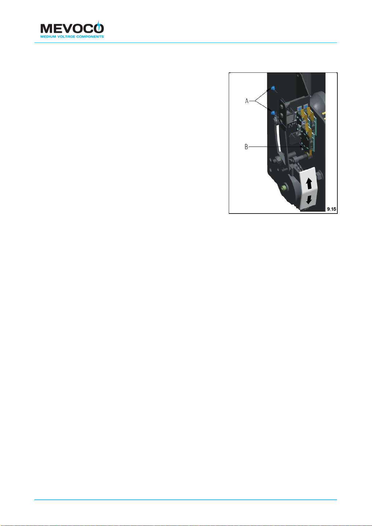
2.6 Mounting instructions for auxiliary contacts of armed spring
Place the auxiliary contact (B) on the desired place
and assemble the auxiliary contact using blind rivets
(A).
Connect the auxiliary contact according to the wiring
diagram
3 FINAL CHECK AND COMMISSIONING
The following actions must always be carried out after mounting the auxiliary contacts:
Check that the fitting materials are properly attached.
Test the auxiliary contacts circuit, in the closed as well as in the open position,
using a multimeter.
Connect the auxiliary contacts electronically using the plug connections according
to the supplied wiring diagram.
Mount the cover of the VA-2 (RP).
Commission the entire medium voltage switchgear and the circuit breaker.

DW702315 © 2015 MEVOCO N.V.
This manual suits for next models
1
Table of contents


