E-T-A ESX10-TA-DC 24 V User manual
- 1 -
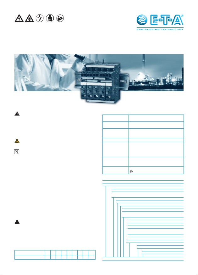
Instruction Manual
Electronic Circuit Protector ESX10-TA/-TB-DC 24 V
Warning
This device is only suitable for operation at 24 VDC (safety
extra-low voltage). Direct connection of this device to a 110 V,
230 V or 400 V power system, or to power systems with a higher
voltage, may consequently result in death, severe personal injury
or substantial property damage. Only qualified personnel should
work on or around this equipment. The product will function
correctly and safely only if it is transported, stored, set up and
installed as intended.
Caution
Electrostatic sensitive devices (ESD) – the device must be opened
only by the manufacturer.
Disposal guideline
Packaging and packing aids can be recycled and should always
be returned to use.
Note
More detailed information can be obtained from local E-T-A subsidiaries
or from the homepage www.e-t-a.de. The product is subject to techni-
cal modifications. In case of doubt the German text takes precedence.
If used under Ex conditions, this device must only be actuated of the
immediate environment is verifiably not classified as a hazardous area.
Automatic start-up of machinery after shut down must be prevented (Ma-
chinery Directive 2006/42/EG and EN 60204-1). In the event of a short
circuit or overload the load circuit will be disconnected electronically by
the ESX10-TA-/TB.
Installation instructions
The type ESX10-TA-/TB can be snapped onto symmetrical rail EN 60715.
Please observe the marking of the ESX10-T signal inputs and outputs,
connection diagrams etc. Before power up the cables have to marked
so as to prevent reverse polarity. The user should ensure that the cable
cross sections of the relevant load circuit are suitable for the current ra-
ting of the ESX10-T used. In the event of Ex applications it has to be
ensured that protection class IP 54 is achieved after installation in a UV-
protected, fully enclosed room / control cabinet. IEC/EN60079-0 and IEC/
EN 60079-14 have be observed for installation.
Safety
This device is not protected against reversed polarity of the input
voltage. It has to be protected against overvoltage > 32 V.
Danger of explosion: Incorrect connection of cables can cause
ignition. The output and the device are protected by an internal,
non-exchangeable blade fuse. Use in aggressive mixed media was
not tested. When mounted side-by-side without convection, the
devices should not carry more than 80 % of its rated load with
100 % ON duty due to thermal effects.
Table
Specifications:
Current rating (A) 0.5 1 2 3 4 6 8 10 12
Max. load (A) 0.5 1 2 3 4 5 7 9 10.8
Protection class to EN60529
housing IP20, terminals IP20
EMC emitted interference to EN 61000-6-3
noise immunity to EN 61000-6-2
Insulation
coordination 0.5 kV / pollution degree 2, re-inforced
insulation in operating area to
IEC60934 / IEC60664
CE logo to 2014/30/EU and 2014/34/EU
UL UL 2367, File # E306740
Solid State Overcurrent Protectors
UL 508, File # E322549
Industrial Control Equipment
ISA 12.12.01-2015, File # E320024
CSA CSA C22.2 No: 14 File # 016186
CSA C22.2 No: 142 File # 016186
CSA C22.2 No: 213
ATEX IEC/EN60079-0 /-14/-15
II 3G Ex nA II B T4 Gc X
!
Type No.
ESX10 Electronic Circuit Protector, with current limitation
Mounting and design
TA rail mounting, without signal contact
TB rail mounting, with aux. contact and hole for signal
busbars/jumpers
Version
1standard, without physical isolation
Signal input
0without signal input
1with control input IN+ (only ESX10-T.-114)
2with reset input RE (only ESX10-T.-124,
ESX10-T.-127)
Signal outputs
0without signal output (only ESX10-TA)
1signal contact N/O
2signal contact N/C
4status output SF (only ESX10-T.-114,
ESX10-T.-124)
7inverse status output SF (only ESX10-T.-127)
Operating voltage
DC 24 V rated voltage DC 24 V
Current rating
0.5...12 A
Approvals
E ATEX
ESX10 -TB-1 0 1-DC 24 V-6 A -E Ordering information
Ordering information
- 2 -
1 Description
Electronic circuit protector type ESX10-T is designed to ensure
selective disconnection of DC 24 V load systems because it responds
much faster to overload or short circuit conditions than the switch-mode
power supply. This is achieved by active current limitation. The ESX10-T
limits the highest possible current to 1.3 to 1.8 times the selected rated
current of the circuit protector. Thus it is possible to switch on capacitive
loads of up to 20,000 µF, but they are disconnected only in the event of an
overload or short circuit.
For optimal alignment with the characteristics of the application the
current rating of the ESX10-T can be selected in fixed values from 0.5
A...12 A. Failure and status indication are provided by a multicolour LED
and an integral short-circuit-proof status output or a potential-free signal
contact. Remote operation is possible by means of a remote reset signal
or a remote ON/OFF control signal. The manual ON/OFF button allows
separate actuation of individual load circuits.
Upon detection of overload or short circuit in the load circuit, the
MOSFET of the load output will be blocked to interrupt the
current flow. The load circuit can be re-activated via the remote
electronic reset input, control input or manually by means of the
ON/OFF button.
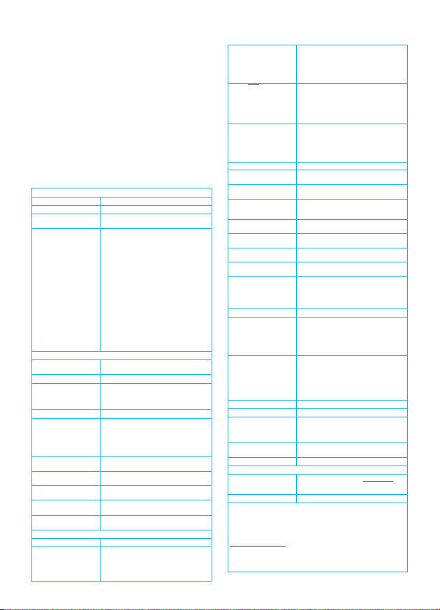
2 Technical Data (Tambient = 25 °C, US= DC 24 V)
Operating data
Operating voltage USDC 24 V (18...32 V)
Current rating IN0.5 A, 1 A, 2 A, 3 A, 4 A, 6 A, 8 A, 10 A, 12 A
Closed current I0ON condition: typically 20...30 mA
depending on signal output
Status indication
by means of
lmulticolour LED:
Green:
- unit is ON, power-MOSFET
is switched on
- status output SF ON, supplies + DC 24 V
Orange:
- in the event of overload or short
circuit until electronic disconnection
Red:
- unit electronically disconnected
- load circuit/Power-MOSFET OFF
OFF:
- manually switched off (S1 = OFF) or
device is dead
- undervoltage (US < 8 V)
- after switch-on till the end of the delay
period
lstatus output SF (option)
lpotential-free signal contact F (option)
lON/OFF/ condition of switch S1
Load circuit
Load output Power-MOSFET switching output
(high side switch)
Overload disconnection typically 1.1 x IN(1.05...1.35 x IN)
Short-circuit current IKActive current limitation with
ILimit = typically 1.8/1.5/1.4/4.3 x IN,
ILimit depending on IN
(typical ILimit - values see table 1)
Trip characteristic active current limitation (see table 1)
Trip thresholds/trip times
(t1, t2) at overcurrent 1. threshold:
at Iload> typically 1.1 x IN...ILimit: (ILimit see
table 1) t1= typically 3s.
2. threshold:
at Iload = ILimit:
t2= typically 100 ms...3 s.
Temperature
disconnection internal temperature monitoring with
electronic disconnection
Low voltage monitoring
load output with hysteresis, no reset required
load “OFF” at US< 8 V
Starting delay tstart typically 0.5 sec after every switch-on
and after applying US
Disconnection of load
circuit electronic disconnection
Free-wheeling circuit external free-wheeling diode
recommended with inductive load
Several load outputs must not be connected in parallel
Status output SF ESX10-T.-114/-124/-127
Electrical data plus-switching signal output, connects US
to terminal 12 of module 17plus nominal
data: DC 24 V / max. 0.2 A (short circuit
proof) status output is internally connected
to GND with a 10 kOhm resistor
Status OUT ESX10-TB-114/-124 (signal status OUT),
at US= +24 V
+24 V = S1 is ON, load output connected
through 0V = S1 is ON, load output blocked
and/or switch S1 is OFF
red LED lighted
Status OUT ESX10-TB-127 (signal status OUT inverted),
at UB= + 24 V
+ 24 V = S1 is ON, load output locked
red LED lighted
0 V = S1 is ON, load output connected and/
or switch S1 is OFF.
OFF condition 0 V level at status output when:
lswitch S1 is in ON position, but device is
still in switch-on delay
lswitch S1 is OFF, or control signal OFF,
device is switched off
lno operating voltage US
Signal output F ESX10-T.-101/-102
Electrical data potential-free signal contact
max. DC 30 V/0.5 A, min. 10 V/10 mA
ON condition LED green oltage USapplied, switch S1 is in ON
position no overload, no short circuit
OFF condition LED off ldevice switched off (switch S1 is in
OFF position)
lno voltage USapplied
Fault condition LED orange overload condition > 1.1 x IN up to
electronic disconnection
Fault condition LED red electronic disconnection upon
overload or short circuit
ESX10-TB-101 single signal, make contact contact
SC/SO-SI open
ESX10-TB-102 single signal, break contact
contact SC/SO-SI closed
Fault signal output fault conditions:
lno operating voltage US
lON/OFF switch S1 is in OFF position
lred LED lighted
(electronic disconnection)
Reset input RE ESX10-T.-124/-127
Electrical data voltage: max. + DC 32 V
high > DC 8 V ≤ DC 32 V
low ≤ DC 3 V > 0 V
power consumption typically 2.6 mA
(+DC 24 V)
min. pulse duration typically 10 ms
Reset signal RE
terminal 22 The electronically blocked ESX10-
TB-124/-127 may remotely be reset via an
external momentary switch due to the fal-
ling edge of a +24 V pulse. A common reset
signal can be applied to several devices
simultaneously. Switched on devices remain
unaffected.
Control input IN+ ESX10-T.-114
Electrical data see reset input RE
Control signal IN+
terminal 21 +24V level (HIGH): device will be switched
(terminal 21) on by a remote ON/OFF
signal 0 V level (LOW): device will be
switched off by a remote ON/OFF signal
Switch S1 ON/OFF unit can only be switched on with S1 if a
HIGH level is applied to IN+
LED display ON: LED green / OFF: LED red
General data
Fail-safe element backup fuse for ESX10-T not required
because of the integral redundant fail-safe
element
Terminals LINE+/LOAD+/0V
screw terminals M4
max. cable cross section
rigid and flexible 0,5 - 16 mm²
flexible with wire end ferrule w/wo plastic sleeve 0.5 - 10 mm2
wire stripping length 10 mm
tightening torque (EN 60934) 1.5 - 1.8 Nm
multi-lead connection
(2 identical cables)
rigid/flexible 0.5 - 4 mm2
flexible with wire end ferrule without plastic sleeve 0.5 - 2,5 mm2
flexible with TWIN wire end ferrule with plastic sleeve 0.5 - 6 mm2
2 Technical Data (Tambient = 25 °C, US= DC 24 V)

- 3 -
Terminals aux. contacts
screw terminals M3
max. cable cross section
flexible with wire end ferrule w/wo plastic sleeve 0.25 – 2.5 mm2
wire stripping length 8 mm
tightening torque (EN 60934) 0.5 - 0.6 Nm
Housing material moulded
Mounting symmetrical rail to EN 60715-35x7.5
Ambient temperature 0...+50 °C (without condensation, see
EN 60204-1)
Storage temperature -20...+70 °C
Humidity 96 hrs/95 % RH/40 °C to
IEC 60068-2-78, test Cab.
climate class 3K3 to EN 60721
Vibration 3 g, test to IEC 60068-2-6 test Fc
Degree of protectio housing: IP20 EN 60529
terminals: IP20 EN 60529
EMC (EMC directive,
CE logo) emission: EN 61000-6-3
susceptibility: EN 61000-6-2
Insulation co-ordination
(IEC 60934) 0.5 kV/2 pollution degree 2
re-inforced insulation in operating area
dielectric strength max. DC 32 V (load circuit)
Insulation resistance
(OFF condition) n/a, only electronic disconnection
Dimensions (W x H x D) 12.5 x 80 x 83 mm
Mass approx. 65 g
2 Technical Data (Tambient = 25 °C, US= DC 24 V)
Schematic diagram ESX10-TB-124 (Example)
Failsafe
Rsense
LINE (+)
DC 24 V
LOAD (+)
load output
0 V
SF status output
RE reset input
status indication
green/orange/red
S1
ON/OFF
electronic control unit
Time/Current characteristic curve (TA= 25 °C)
disconnection
typically 1.1 x IN
I
K
10000
1000
124
trip time in second
s
...times rated current
100
10
1
0.1
0.01
35
0
1.8 x IN
5
current limitation
typically 1.8 x IN
lThe trip time is typically 3 s in the range between 1.1 and 1.8 x IN
(e.g. ESX10-TB-...-6 A)
lElectronic current limitation ILimit occurs at typically 1.8 x IN
which means that under all overload conditions (independent
of the power supply and the resistance of the load circuit)
the max. overload before disconnection will not exceed 1.8
x INtimes the current rating. The individual current limitation
value ILimit depends on the current rating (see table1). Trip
time is between 100 ms and 3 sec (depending on overload
or at short circuit).
lWithout this current limitation a considerably higher overload
current would flow in the event of an overload or short circuit.
ESX10-T Signal inputs / outputs (wiring diagram)
ESX10-T signal inputs / outputs (schematic diagrams)
Auxiliary contacts are shown in OFF or error condition
LINE+ 1
LOAD+
2
0V 3
LINE+ 1
14
13
2LOAD+
0V 3
LINE+ 1
12
11
2LOAD+
0V 3
LINE+ 1
SF 23
IN 21
2LOAD+
0V 3
LINE+ 1
SF 23
RE 22
2LOAD+
0V 3
LINE+ 1
SF 23
RE 22
2LOAD+
0V 3
ESX10-TA-100
without signal input/output
ESX10-TB-101
without signal input
with signal output F
(single signal, N/O)
ESX10-TB-102
without signal input
with signal output F
(single signal, N/C)
ESX10-TB-114
with control input IN+
(+DC 24 V)
with status output SF
(+24 V = load output ON)
operating
condition:
13-14 closed
fault condition:
13-14 open
operating
condition:
11-12 open
fault condition:
11-12 closed
operating
condition:
SF +24 V = OK
fault condition:
SF 0 V
ESX10-TB-124
with reset input RE
(+DC 24 V ↓)
with status output SF
(+24 V = load output ON)
ESX10-TB-127
with reset input RE
(+DC 24 V ↓)
with inverse status output SF
(0 V = load output ON)
operating
condition:
SF +24 V = OK
fault condition:
SF 0 V
operating
condition:
SF 0 V = OK
fault condition:
SF +24 V

- 4 -
Connection diagrams and application examples ESX10-T
ESX10-TA-100
ESX10-TB-101
group signalling (series connection)
ESX10-TB-102
Single signalling with common line entry
ESX10-TB-124
Single signalling with common reset
+24V
0V
Load Load Load
+- +- +-
+- +- +-
ESX10-TA-100
1
LINE+
1
LINE+ 1
LINE+
ESX10-TA-100 ESX10-TA-100
3 0V
3 0V 3 0V 3 0V
3 0V 3 0V
2 LOAD+ 2 LOAD+ 2 LOAD+
+24V
0V
Load Load Load
13
1
LINE+
14
ESX10-TB-101
2 LOAD+
13
1
LINE+
14 13
1
LINE+
14
ESX10-TB-101
2 LOAD+
ESX10-TB-101
2 LOAD+
+24V
0V
11
1
LINE+
12 11
1
LINE+
12 11
1
LINE+
12
2 LOAD+
ESX10-TB-102
3 0V 3 0V 3 0V
2 LOAD+
ESX10-TB-102
2 LOAD+
ESX10-TB-102
Load Load Load
+- +- +-
Connection diagrams and application examples ESX10-T…
Signal contacts are shown in OFF or fault condition.
power
supply
DC 24 V
power
supply
DC 24 V
power
supply
DC 24 V
terminals for
busbars
screw
terminals
LINE+ busbar
(X 222 611 02
or X 222 611 xx)
0 V busbar
(X 222 611 02
or X 222 611 xx)
- line entry
- line entry
- line entry
+ line entry
+ line entry
+ line entry
+ line entry for the SI
+ line entry for the SI
LINE + busbar
(X 222 611 02 or X 222 611 xx)
group signalling
by means of an
signal lamp
jumpers
(X 222 005 13)
are staggered
0 V busbar
(X 222 611 02
or X 222 611 xx)
signal busbar
(X 222 005 03)
for common
line entry
0 V busbar
(X 222 611 02
or X 222 611 xx)
LINE+ busbar
(X 222 611 02
or X 222 611 xx)
single signalling
per way
by means of
an LED
+24V
0V
+ line entry
- line entry
+ line entry
- line entry
+ line entry
- line entry
2 LOAD+
ESX10-TB-124
2 LOAD+
ESX10-TB-124
2 LOAD+
ESX10-TB-124
Load Load Load
22
1
LINE+
RE SF 23 22
1
LINE+
RE SF 23 22
1
LINE+
RE SF 23
Reset
button
3 0V 3 0V 3 0V
+- +- +-
+ 24 V
0 V
0,5 A
ESX10-TA-100
1
LINE+ 1
LINE+ 1
LINE+ 1
LINE+
2 LOAD +2LOAD +2LOAD +2LOAD+
3 0V3 0V 3 0V 3 0V
13 13 1314 14 14
ESX10-TB-101 ESX10-TB-101 ESX10-TB-101
Load Load Load
+- +- +-
3 0V3 0V 3 0V 3 0V
+ 24 V
0 V
0,5 A
ESX10-TA-100
1
LINE+ 1
LINE+ 1
LINE+ 1
LINE+
2 LOAD+2LOAD+2LOAD+2LOAD+
11 11 1112 12 12
ESX10-TB-102 ESX10-TB-102 ESX10-TB-102
Load Load Load
+- +- +-
power
supply
DC 24 V
power
supply
DC 24 V
power
supply
DC 24 V
signal busbar
(X 222 005 03)
for common reset
0 V busbar
(X 222 611 02
or X 222 611 xx)
LINE+ busbar
(X 222 611 02
or X 222 611 xx)
single signalling per
way by means of
an LED
Application examples: line entry DC 24 V with
protection of signal circuit and direct connection of loads
Auxiliary contacts are shown on the OFF of fault condition
ESX10-TB-101
Group signalisation (series connection)
Type ESX10-TA-100-DC24V-0.5A can be used as a
supply module including protection of auxiliary circuit
Optional: Passive supply module AD-TX-EM01 (without protection)
+ line entry for SI
+ line entry for SI
LINE+ busbar
(X 222 611 02
or X 222 611 xx)
jumpers
(X 222 005 13)
are staggered
group
signalisation
by means of a
signal lamp
0 V busbar
(X 222 611 02
or X 222 611 xx)
ESX10-TB-102
Single signalisation with common line entry
Type ESX10-TA-100-DC24V-0.5A can be used as
a supply module
including protection of auxiliary circuit
Optional: Passive supply module AD-TX-EM01 (without protection)
LINE+ busbar
(X 222 611 02
or X 222 611 xx)
signal busbar
(X 222 005 03)
for common
line entry
0 V busbar
(X 222 611 02
or X 222 611 xx)
single signalisation per way
by means of an LED

- 5 -
Mounting examples for ESX10-T
5 ESX10-TA
with busbars
5 ESX10-TB
with busbars
and jumpers
12.5 x n = width of protector block
e. g. 12.5 x 5 = 62.5
insert busbars
and protection slides
to be flush with housing sides
insert signal bars to
be flush with housing
and place them centrally
over the contacts
LINE+ busbar
X22261102 grey
or X222611xx
0 V busbar
X22261102 grey
or X222611xx
signal bar
X22200503 grey
or X222005xx
or
jumper
X22200513 grey
remove protection
against brush contact
from bottom side
(12.5 x n)-3 = length of busbars ± 0.5
e. g. (12.5 x 5)-3 = 59.5 ± 0.5
insert protection
against
brush contact
continuous busbar
500 mm length, cut
Mounting procedure:
Before wiring insert busbars into protector block.
Max. 10 insertion/removal cycles for busbars.
Recommendation:
After 10 units the busbars and signal busbars should be interrupted and receive a new entry live
Table of lengths for busbars
(X 222 611 02 / X 222 005 03 or cut off, see accessories)
No. of units 2 3 4 5 6 7 8 9 10
Length of busbar (mm) ± 0.5 mm 22 34.5 47 59.5 72 84.5 97 109.5 122

- 6 -
4 Accessories
4.1 Description
The ESX10-T features an integral power distribution system. The
following wiring modes are possible with various pluggable current
and signal busbars:
• LINE +(DC 24 V)
• 0 V
Caution: The electronic devices ESX10-T require a
0 V connection
• signal contacts
• reset inputs
4.2 Accessories
Use original E-T-A accessories only!
lBusbars for LINE+ and 0 V
max. load with one line entry
(recommended: centre line entry)
max. load with two line entries
grey insulation, length: 500 mm
X 222 611 02
lBusbars for LINE+ and 0 V
grey insulation
max. number of plug-on operations 10:
X 222 611 22
(2-unit-block ESX10-T), length: 22 mm
X 222 611 34,
(3-unit-block ESX10-T), length: 34.5 mm
X 222 611 47,
(4-unit-block ESX10-T), length: 47 mm
X 222 611 59,
(5-unit-block ESX10-T), length: 59.5 mm
X 222 611 72,
(6-unit-block ESX10-T), length: 72 mm
X 222 611 97,
(8-unit-block ESX10-T), length: 97 mm
X 222 611 12,
(10-unit-block ESX10-T), length: 122 mm
lSignal busbars for signal contacts and reset inputs
suitable for signal busbar ESX10-TB-...
max. load with one line entry
with one series connection of signal contacts Imax
grey insulation, length: 500 mm
X 222 005 03
lJumpers for signal contacts
suitable for jumper ESX10-TB-...
grey insulation, length: 21 mm
X 222 005 13
lInsulated wire bridge
optional as jumper for ESX10-TB-101...
for group signalisation (series connection)
X 223 108 01
lConnector bus link –K10
suitable for auxiliary contacts (series connection)
X 210 589 02 (1.5 mm2, brown)
3 Informationen on UL-approvals/
CSA-approvals
ESX10-TA / -TB
UL2367
Non-hazardous use
UL File # E306740
UL 508
Non-hazardous use
UL File # E322549
E322549
INDUSTRIAL CONTROL EQUIPMENT
ESX10-TA / -TB
ISA 12.12.01-2015
UL File # E320024
Operating Temperature Code T4
- This equipment is suitable for use in Class Ⅰ, Division 2,
Groups A, B, C and D or non-hazardous locations only. T4 A / 0
°C to 50 °C
WARNING:
- Exposure to some chemicals may degrade the sealing properties
of materials used in the following device: relay (K1)
Sealant Material:
Generic Name: Modified diglycidyl ether of bisphenol A
Supplier: Fine Polymers Corporation
Type: Epi Fine 4616L-160PK
Casing Material:
Generic Name: Liquid Crystal Polymer
Supplier: Sumitomo Chemical
Type: E4008, E4009, or E6008
RECOMMENDATION:
- Periodically inspect the device named above for any degradation
of properties and replace if degradation is found
WARNING – EXPLOSION HAZARD:
AVERTISSEMENT – RISQUE D’EXPLOSION
- Do not disconnect equipment unless power has been removed or the
area is known to be non-hazardous.
- Avant de deconnecter l’equipment, couper le courant ou s’assurer
que l’emplacement est designe non dangereux.
- Substitution of any components may impair suitability for Class Ⅰ,
Division 2.
La substitution de composants peut rendre ce materiel inacceptable
pour les emplacements de class Ⅰ, division 2.
This device is OPEN type equipment that must be used within a suitable
end-use system enclosure, the interior of which is accessible only
through the use of a tool. The suitability of the enclosure is subject
to investigation by the local Authority Having Jurisdiction at the time
of installation.
Wiring to or from this device, which enters or leaves the system enclosu-
re, must utilize wiring methods suitable for Class Ⅰ, Division 2 Hazardous
Locations, as appropriate for the installation.
ESX10-TA / -TB
CSA C22.2 No: 14 - File # 016186
CSA C22.2 No: 142 - File # 016186
CSA C22.2 No: 213
(Class Ⅰ, Division 2) - File # 016186
Class 2
Meets requirement for Class 2 current limitation
(ESX10-T...-0.5 A / 1 A / 2 A / 3 A)

- 7 -

- 8 -
E-T-A Elektrotechnische Apparate GmbH
Industriestraße 2-8 · 90518 ALTDORF
GERMANY
Phone: +49 9187 10-0 · Fax +49 9187 10-397
All dimensions without tolerances are for reference only. In the interest
of improved design, performance and cost effectiveness the right
to make changes in these specifications without notice is reserved.
Product markings may not be exactly as the ordering codes. Errors
and omissions excepted.
http://www.e-t-a.de/qr1006/
Bedienungsanleitung ESX10-TA/TB-.-E (D/E)
Bestell-Nr. / Ref. number Y31040901 Index: b
Ausgabe / Issue: 10/2017 / Alle Rechte vorbehalten / All rights reserved
This manual suits for next models
1


