Meynell V8/3 User manual

1
V8/3
THERMOSTATIC
MIXING VALVE
PRODUCT MANUAL
IMPORTANT
Installer: This Manual is the property of the customer
and must be retained with the product for
maintenance and operational purposes.

2
CONTENTS
Safety : Warnings ....................................................................................3
Advice.......................................................................................................3
Description...............................................................................................4
Pack Contents ......................................................................................... 5
Dimensions ..............................................................................................7
Specications ..........................................................................................8
Installation Requirements .................................................................... 10
Installation .............................................................................................12
General............................................................................................... 12
Reverse Outlet Connector .................................................................13
1. Exposed Models ............................................................................14
2. Built-in Models................................................................................15
Commissioning .....................................................................................17
Exercising the Thermostat..................................................................17
Commissioning Checks......................................................................17
Maximum Temperature.......................................................................18
Maximum Temperature Setting ..........................................................18
Operation ...............................................................................................19
Fault Diagnosis......................................................................................20
Maintenance...........................................................................................21
General............................................................................................... 21
Planned Maintenance............................................................................22
Healthcare..........................................................................................22
Frequency of In-service Tests ...........................................................22
Checkvalves and Filters .....................................................................23
Type 2 and Type 3 Valves...................................................................... 25
Application..........................................................................................25
Installation Conditions ........................................................................ 26
Commissioning...................................................................................26
Maintenance.......................................................................................27
Spare Parts ............................................................................................ 28
Notes ......................................................................................................30
Customer Care.........................................................................Back Page

3
The function of a thermostatic mixing valve is to deliver water consistently at a safe
temperature. This requires that:
1. It is installed, commissioned, operated and maintained in accordance with the
recommendations given in this manual.
2. Type 2 and 3 valves are only used for applications covered by their approved
designations.
3. Periodic attention is given, as necessary, to maintain the product in good functional
order. Recommended guidelines are given in section: ‘Maintenance’.
4. Continueduseofthisproductinconditionsoutsidethespecicationlimitsgiven
in this Manual can present potential risk to users.
SAFETY : WARNINGS
ADVICE
The use of the word ‘failsafe’ to describe the function of a thermostatic mixing valve
is both incorrect and misleading. In keeping with every other mechanism it cannot
be considered as being functionally infallible.
Provided that the thermostatic mixing valve is installed, commissioned, operated
withinthespecicationlimitsandmaintainedaccordingtothisManual,theriskof
malfunction, if not eliminated, is considerably reduced.
Malfunction of thermostatic mixing valves is almost always progressive in nature
and will be detected by the use of proper temperature checking and maintenance
routines.
Certain types of system can result in the thermostatic mixing valve having excessive
‘dead-legs’ of pipework. Others allow an auxiliary cold water supply to be added
to the mixed water from the mixing valve. Such systems can disguise the onset of
thermostatic mixing valve malfunction.
Ultimately, the user or attendant must exercise due diligence to ensure that the
delivery of warm water is at a stable, safe temperature. This is particularly important
in such healthcare procedures as supervised bathing of patients unable to respond
immediately to unsafe temperatures.
IfyouexperienceanydifcultywiththeinstallationoroperationofyournewMixing
Valve, then please refer to “Fault Diagnosis”, before contacting Kohler Mira Ltd.
Our telephone and fax numbers can be found on the back cover of this guide.

4
INTRODUCTION
The Meynell V8/3 is a Thermostatic Mixing Valve specied to meet the highest
standards of safety, and reliability as demanded by today’s users. All Meynell products
are designed, manufactured and supported in accordance with accredited BS EN
ISO 9001: 2000 Quality Systems.
This Manual covers all Meynell V8/3 Thermostatic Mixing Valves manufactured from
June 1997.
Thesufx‘3’indicatesthatthismixerhasbeencertiedforuseinUKHealthcare
premises as a Type 3 valve under the BUILDCERT TMV3 scheme. For Healthcare
installation refer to section: ‘Type 2 and Type 3 Valves’. In this case this product
hasalsobeencertiedasaType2valveundertheBUILDCERTTMV2scheme.This
productalsocomplieswiththeWaterSupply(waterttings)Regulations1999.
A point of use Thermostatic Mixing Valve designed to supply temperature controlled
hot water to both single and multi-point installations.
Meynell V8/3:
Exposedorbuilt-inmodelwithstublever,allchromenish,swivelelbowsexcept
rising, falling or rear entry supplies. 15 mm compression inlet, 1/2” BSP or 15 mm
outlet connections.
Meynell V8/3 L:
Exposedorbuilt-inmodelwithlongleverfordisableduse,allchromenish,15mm
compression inlet, 1/2” BSP or 15 mm outlet connections.
Meynell V8/3 K:
Exposedmodelwithlocked(non-adjustable)controlknob,allchromenish,15mm
compression inlet, 1/2” BSP or 15 mm compression outlet connections.
DESCRIPTION

5
PACK CONTENTS
Exposed Models
Tick the appropriate boxes to familiarize yourself with the part names and to
conrmthatthepartsareincluded.
Documentation
1 x NHS Requirements Booklet
1 x V8/3
1 x V8/3 L
1 x V8/3 K
1 x Hexagonal Key
3 x Fixing Screws
1 x Olive
1 x Compression Nut
Or
Or

6
Built-in Models
1 x Hexagonal Key
3 x Fixing Screws
Documentation
1 x NHS Requirements Booklet
1 x V8/3 B
1 x V8/3 BL
1 x Foam Seal
1 x Rubber Grommet
1 x Concealing Plate

7
DIMENSIONS
Exposed Model
Built-in Model
160 mm
130 mm Centres
122.5 mm
65 mm
35 mm
161 mm
124 mm
55 mm MAX
35 mm MIN
122.5 mm
35 mm

8
Normal Operating Conditions are considered as:
inlet maintained pressures are nominally balanced
daily usage 1-6 hours
installation and usage environment not subject to extremes of temperature,
unauthorised tampering or wilful abuse.
Operating Parameters
ForType2and3valvesthesupplyconditionsspeciedinsection:‘Type 2 and
Type 3 Valves, Application’ take precedence over the operating parameters which
follow.
Pressures And Flow Rates
For optimum performance, maintained supply pressures should be nominally
equal.
Maximum Pressure Loss Ratio: 10:1
Minimum Maintained Pressure: 0.1 bar (= 1 metre head from underside of cold tank
tooutletofshowertting)
Maximum Static Pressure: 10 bar
•
•
•
SPECIFICATIONS
0.1 0.2 0.3 0.4 0.5 1.0 2.0
0
5
10
15
20
25
30
35
40
45
PressureLoss(bar)
FlowRate(L/Min)
Thermostatic Mixing Valve

9
Temperature Control
Minimum temperature differential between hot and outlet temperature: 10°C
Optimum temperature control range: 35 - 45°C
Maximum hot water temperature: 85°C (for safety, a recommended hot water storage
temperature maintained below 85°C and for ablutionary installations at between
60 to 65°C).
The performance specification outlined below is achieved with outlet blend
temperature set between 35 - 45°C and supplies of 15°C cold and 65°C hot with
nominally equal pressures.
Outlet blend temperature is maintained within 2°C with a 10°C change in hot
or cold supply.
Thermostatic shut down to seepage within 2 seconds if cold supply fails. This is
achieved only if the hot supply temperature is 10°C above the set outlet blend
temperature.
Connections
Inlet connectors are 15 mm compression
Outlet connector is 1/2” BSP Male or 15 mm compression
Hot(H)andCold(C)inletsareclearlymarkedandmustbeconnectedthisway.
•
•

10
INSTALLATION REQUIREMENTS
Isolating Valve
Mixing Valve
OverowIndicator
Pressure Reducing Valve
Float Valve Twin Impeller Pump
Single Impeller Pump
Tempering Valve
Mini Expansion Vessel
Key to Symbols
The Meynell V8/3 Thermostatic Mixing Valve is compatible with the following
systems:
Gravity fed system
The Mixing Valve MUST be fed from a
cold water cistern and hot water cylinder
providing nominally equal pressure.
Gas heated system
The Mixing Valve MUST be installed with
a gas water heater or combination boiler
of a fully modulating design.

11
Unvented mains pressure system
The Mixing Valve can be installed with a
unvented, stored hot water cylinder.
Mains pressurised instantaneous hot
water system (thermal store)
The Mixing Valve can be installed with
systems of this type with balanced
pressures.
Pumped system
The Mixing Valve can be installed with an
inletpump(twinimpeller).Thepumpmust
be installed on the oor next to the hot
water cylinder.
Air Separation
30°-60°
90°

12
INSTALLATION
General
Installation must be carried out in accordance with these instructions, and must be
conductedbydesignated,qualiedandcompetentpersonnel.
1. Before commencing, make sure that the installation conditions comply with the
information given in section: ‘Specications’. For Type 2 and 3 valves see also
Installation conditions in section: ‘Type 2 and Type 3 Valves’.
2. Care must be taken during installation to prevent any risk of injury or
damage.
3. The mixing valve should be positioned for easy access during use and
maintenance. All routine maintenance procedures can be conducted with the
mixingvalvebodyinplace(exceptforstrainerandcheckvalveaccess).Forall
models, allow a minimum 80 mm clearance in front of the temperature control
to enable removal of the serviceable parts during maintenance. Conveniently
situated isolating valves must be provided for maintenance.
4. The use of supply-line or zone strainers will reduce the need to remove debris at
each mixing valve point. The recommended maximum mesh aperture dimension
for such strainers is 0.5 mm. Inlet pressure tappings which allow measurement
of inlet pressure to the mixing valve under operating conditions are particularly
recommended for healthcare with Type 2 and 3 valves.
5. Pipework must be rigidly supported.
6. Pipework dead-legs should be kept to a minimum. The mixed water outlet piping
should not exceed 2 m and the overall length from the hot water circuit to the
discharge point should not exceed 5 m.
7. Supply pipework layout should be arranged to minimise the effect of other outlet
usage upon the dynamic pressures at the mixing valve inlets.
8. Inlet and outlet threaded joint connections should be made with PTFE tape or
liquid sealant. Do not use oil-based, non-setting jointing compounds.
9. Toeliminatepipedebrisitisessentialthatsupplypipesarethoroughlyushed
through before connection to the mixing valve.

13
25 mm
Spill Over
Level
Hose Retaining Ring
10. Decide on a suitable position for the
Mixing Valve. The position of the
Mixing Valve and the Shower Fittings
must provide a minimum gap of
25 mm between the spill-over level of
the shower tray/bath and the handset.
This is to prevent back-siphonage. For
further information on the installation
of your shower ttings, refer to the
Fittings Installation and User Guide.
Note! Only use shower fittings
recommended by the manufacturer
or supplier.
Reverse Outlet Connector
IftheShowerOutletneedstobereversed(e.g.bottomoutlettotopoutlet):
1. RemovetheBlankingCap(iftted).
2. Using a 1/2” hexagonal key remove the Sealing Plug from the top and the Outlet
Connector from the bottom of the Thermostatic Mixing Valve.
3. Swaparoundandret,ifchangingfromatconnectortocompressionmake
sure that the ‘O’ Seal is changed around.
4. Retinreverseorder.
Coned End
Coned End
Flat End
Blanking Cap
Sealing Plug
‘O’ Seal
Outlet
Connector
Olive
Compression
Nut
‘O’ Seal
‘O’ Seal
14
1. Exposed Models
1.1 Decide on a suitable position for the
Thermostatic Mixing Valve where all
users can operate it.
1.2 Remove the Wall Bracket from the rear
of the Mixer Valve Body by loosening
the Wall Bracket Grubscrew with a
2.5mmhexagonalkey(supplied).
1.3 Use the Wall Bracket to mark 3 hole
positions. Drill wall and insert suitable
Wall Plugs (not supplied) for No.10
FixingScrews(supplied).
1.4 The Thermostatic Mixing Valve is
supplied for rising supplies.
For Falling or Rear Entry supplies
loosen the Elbow Grubscrew and
rotate the Elbow to the required
position. Then secure with the
Grubscrew.
1.5 Fit the supply pipework (Hot - Left,
Cold-Right).
Caution! It is essential at this point
that the supply pipework is thoroughly
ushed through before connection
to the Thermostatic Mixing Valve.
Failure to do so may result in product
malfunction.
1.6 Locate the Thermostatic Mixing Valve
onto the pipework and secure to the
Wall Bracket with the Grubscrew.
1.7 Tighten the Compression Nuts and
Olives using a suitable spanner.
1.8 Install the Shower Fittings, refer to
your Shower Fittings Installation and
User Guide.
1.9 Turn on the hot and cold water
supplies and check for leaks.
Hexagonal Key
Elbow
Inlet Pipework
Fixing Screws
Wall Bracket
Wall Plugs
(notsupplied)
Inlet Pipework
(rearsupplies)
35 mm
35 mm

15
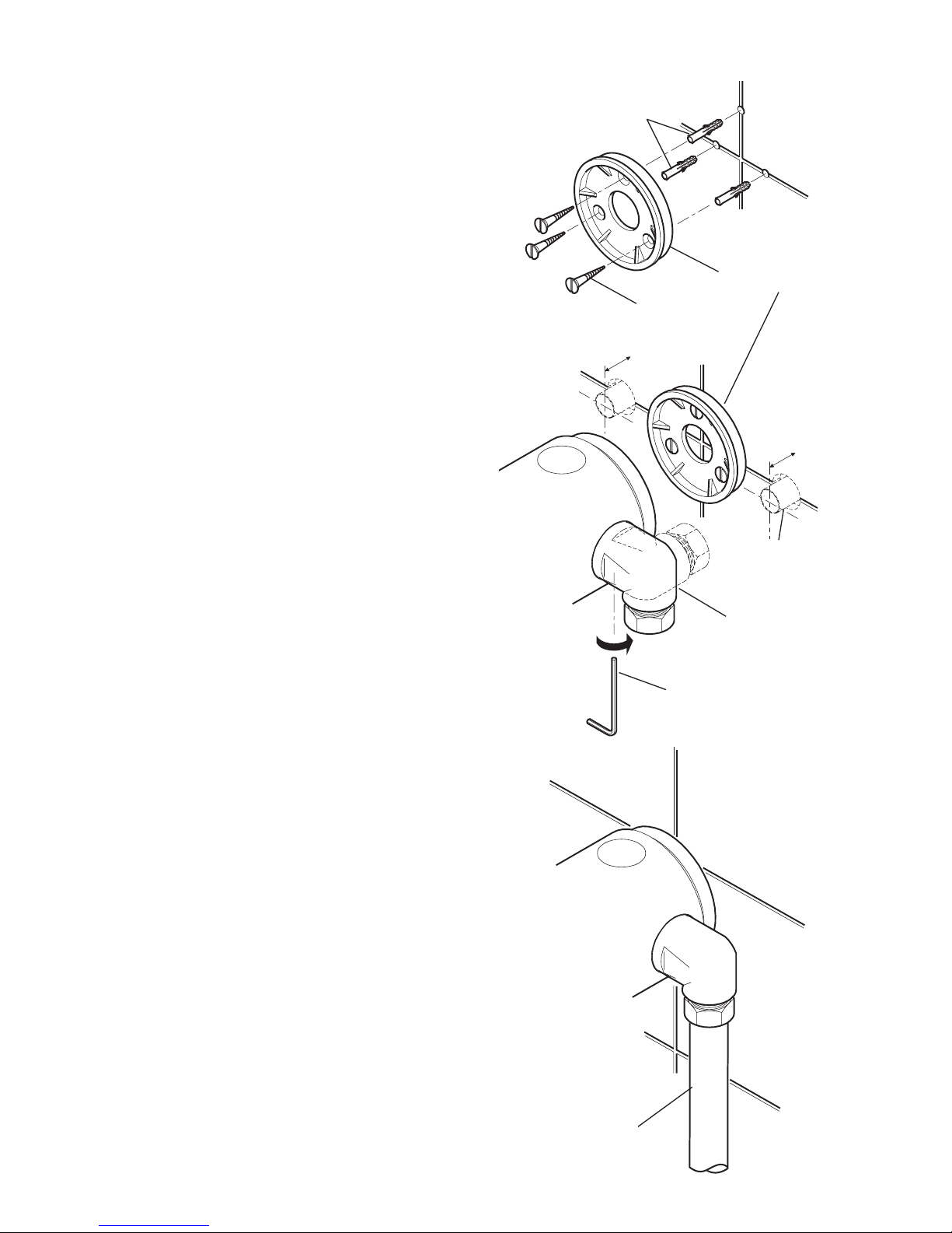
2. Built-in Models
2.1 Decide on a suitable position for the
Thermostatic Mixing Valve where all
users can operate it.
2.2 Determine the routes of the incoming
hot and cold supply pipework. They
can be rising or falling supplies.
2.3 Determine the route for the outlet
pipework. When connecting the
Shower Fittings to the outlet they
should be to the side and above the
Thermostatic Mixing Valve to make
sure that the Flexible Hose hangs
correctly and does not obstruct the
Shower Control. The outlet can be
sited on the right or on the left, as site
dictates.
2.4 Mark suitable routes for inlet and
outlet pipework.
2.5 Cut away plasterboard and brick
work to a depth of between 60 mm
to 80 mm. Depth should be 67 mm
min/87mmmaxincludingnishwall
thickness(tilesorfaciaboard).
2.6 Fit the supply pipework
(Hot-Left,Cold-Right).
Caution! It is essential at this point
that the supply pipework is thoroughly
ushed through before connection
to the Thermostatic Mixing Valve.
Failure to do so may result in product
malfunction.
2.7 Fix the Thermostatic Mixing Valve
to the wall or timber noggin (refer to
section: ‘1. Exposed Models’ and
followinstructions1.2and1.3).
2.8 Make the connections to the inlets
and outlet of the Thermostatic Mixing
Valve as shown
2.9 Tighten the Compression Nuts and
Olives using a suitable spanner.
2.10Turn on the hot and cold water
supplies and check for leaks.
ColdHot
Outlet
Shower
Outlet
Alternative
Routes

16
2.11Plaster and tile up to the Thermostatic
Mixing Valve, leaving a maximum
diameter hole around the Mixing Valve
of 125 mm.
2.12Fit the Sealing Grommet to the inner
diameter of the Concealing Plate.
Remove the protective backing from
onesideoftheFoamWasherandx
to rear of the Concealing Plate.
2.13Unscrew the Control Knob Grubscrew
and remove the Control Knob.
2.14Check that the Concealing Plate will
cover the installation hole.
2.15Peel the second protective backing
from the Foam Washer and t over
the Thermostatic Mixing Valve.
Push evenly on the Concealing
Plate to make sure that the adhesive
backingprovidesasufcientseal.
2.16RetandsecuretheControlKnob.
Sealing Grommet
Concealing
Plate
Foam Seal
Control Knob
Concealing Plate
(apply pressure
evenly)

17
COMMISSIONING
Commissioning must be carried out in accordance with these instructions, and must
beconductedbydesignated,qualiedandcompetentpersonnel.
Exercising the Thermostat
Thermostatic Mixing Valves are inclined to lose their responsiveness if not used.
Valves which have been in storage, installed but not commissioned, or simply not
used for some time should be exercised before setting the maximum temperature
or carrying out any tests.
A simple way to provide this exercise is:
(a) makesurethatthehotandcoldwaterareavailableatthevalveinlets,
and the outlet is open.
(b) movethetemperaturecontrolrapidlyfromcoldtohotandhotbackto
cold several times, pausing at each extreme.
Commissioning Checks
(Temperatures should always be recorded using a thermometer with proven
accuracy)
1. Check the inlet pipework temperature for correct function of the checkvalves.
2. Operate the Meynell V8/3 and check:
Flowrateissufcientforpurpose
Temperature obtainable is acceptable
All connections are watertight.
3. It is advisable to establish a performance check at this time, which should
be noted for future reference as part of a Planned Maintenance Program (a
MaintenanceRecordCardhasbeenprovidedwiththisManual).
The procedure should be chosen to imitate both typical and difcult operating
conditions,suchasanysupplypressureuctuationsthatmaybelikely.Anideal
method is to locate another outlet on the common cold water supply close to the
Thermostatic Mixing Valve (operating this outlet should cause a drop in supply
pressure),andnotethesubsequenteffectonblendtemperature.Thisshouldbeno
morethan2°Cchange).
Note! Causing thermal shutdown of the Meynell V8/3 by full closure of the cold
supply may not adequately indicate the practical capability of the Meynell V8/3, nor
its service condition. Consequently this is not a recommended performance check,
and repeated such testing may ultimately affect service life.
•
•
•

18
1. Turn on the Thermostatic Mixing Valve
to its maximum setting, (for Lockshield
models turn on the separate outlet
device tted eg. stopvalve). Let the
temperature stabilise.
2. Unscrew the Control Knob Grubscrew
and remove the Control Knob or
Lockshield.
3. Insert the 2.5 mm hexagon key into
the centre of Mixing Valve Head.
4. Turn the hexagon key anticlockwise
to increase the temperature, or
clockwise to decrease temperature.
5. Refit and secure the Control
Knob or Lockshield and turn off
the Thermostatic Mixing Valve (on
lockshield models turn off the outlet
device).
Note! The Control Knob should be
ttedwiththe‘brand’horizontal.
Note! For Lockshield models make
sure that the anti-rotation slots
are engaged on the Lug on the
Mixing Valve Body (refer to arrow on
illustration).
Maximum Temperature
The maximum blend temperature obtainable by the user should be limited, to prevent
accidental selection of a temperature that is too hot.
The Meynell V8/3 is fully performance tested, and the maximum temperature is preset
to approximately 42°C under ideal installation conditions at the factory.
Site conditions and personal preference may dictate that the maximum temperature
has to be reset following installation.
Maximum Temperature Setting
Make sure that an adequate supply of hot water is available at the hot inlet of the
Meynell V8/3 and that both inlet isolating valves are fully open.
The minimum temperature of the hot water must be at least 10°C above the desired
blend, however during resetting this should be close to the typical storage maximum
tooffsetthepossibilityofanyblendshiftduetouctuatingsupplytemperatures.
Cooler
Warmer
Lockshield Model

19
Temperature selection (not lockshield model).
The mixer has one control to set temperature and works in a sequence:
Off→Cold→Tepid→Pre-setMaximum
OPERATION
Preset Maximum
Temperature
Off

20
FAULT DIAGNOSIS
Symptom Cause/Rectication
1. Only hot or cold
water from mixer
outlet.
a. Inletsuppliesreversed(hotsupplytocoldsupply).
b. No hot water reaching mixer.
c. Checkstrainersandinlet/outletttingsforblockage.
d. Installation conditions continuously outside operating
parameters, refer to section: ‘Specications’ and 2.e
below.
2. Fluctuating or
r e d u c e d f l o w
rate.
Normal function of the thermostatic control when operating
conditions are unsatisfactory.
a. Checkstrainersandinlet/outletttingsforblockage.
b. Makesureminimumowrateissufcientforsupply
conditions.
c. Make sure the maintained inlet pressures are
nominallybalancedandsufcient.
d. Make sure the inlet temperatures differentials are
sufcient.
e. (Subsequent to rectication of supply conditions)
Check thermostatic performance; renew Piston
Assembly if necessary.
3. Noowratefrom
mixer outlet.
a. Checkstrainersandinlet/outletttingsforblockage.
b. Hot or cold supply failure.
4. Blend temperature
drift.
Indicates operating conditions changed.
a. Refer to symptom 2. above.
b. Hotsupplytemperatureuctuation.
c. Supplypressuresuctuating.
d. Seal damage or wear. Renew seals.
5. Maximum blend
temperature
setting too hot or
too cold.
a. Indicates incorrect maximum temperature setting;
refer to section: ‘Commissioning’.
b. As symptom 4. above.
6. Water leaking
from mixer body.
Seal wear or damage.
a. Obtain Seal Kit, renew all seals.
7. Flow rate too high
or too low.
a. (Toolow)Refertosymptom2.a-e. above.
b. (Toolow)Insufcientsupplypressures.
c. (Toohigh)Supplypressuretoohigh.
d. (Toohigh)Refertosymptom2.a-e. above.
Table of contents
Popular Control Unit manuals by other brands

IMI Hydronic
IMI Hydronic IMI TA TA-MIX quick start guide

Rohde & Schwarz
Rohde & Schwarz R&S OSP-B157W8 user manual

AXIOMTEK
AXIOMTEK Q7M310 user manual

Pentair
Pentair F251 Installation & maintenance instructions

Edwards
Edwards SCU-800 instruction manual

Texas Instruments
Texas Instruments DAC7731 user guide


