Meyra TA R-Net CJSM2 User manual

OPERATING MANUAL
R-Net CJSM2
This product fulfils the requirements of
Regulation (EU) 2017/745 on medical devices.
300-49 UM CJSM2 - GB - 06.2021, vers. 1:0

2
Contents
Symbol key 5
Introduction 5
Models 5
Specications 5
Usage 5
Adjustment 6
Reuse 6
Product life span 6
Safety precautions 6
Connecting two control modules 7
Overview 8
CJSM2 <LCD> Joystick Module 8
Push-button control panel 8
Symbols control panel 8
LCD screen 9
Attendant control 10
Push-button control panel 10
LED indicators 10
Buttons and symbols 11
Attendant control 12
LCD screen 13
Before use 15
Charging the batteries 15
Connecting the joystick module 15
Lock 16
Deactivating the lock 17
Auto-shutdown 18
Pre-drive inspection 19
Battery indicator 19
Interpretation 19
Pre-set maximum speed 20
Attendant control 21
Speed levels 22

3
Mode menu 23
Drive mode 23
Settings mode 23
Joystick 24
Driving and steering manoeuvres 24
Braking the electric wheelchair 24
Attendant control 25
Selecting a control mode 25
Electronic adjustments 26
Selecting an electronic adjustment 26
Standard electronic adjustments 26
Complex electronic adjustments 27
Individual features/settings 29
Odometer (total kilometres) 29
Trip counter 29
Resetting the trip counter 29
Driving program 30
Settings menu 31
Accessing the Settings menu 32
Menu navigation 32
Gyro 33
Enabling/disabling Gyro 33
External connectivity options 34
Connecting external button controllers 34
IR interface 35
Entering IR remote control codes 35
Bluetooth 36
Troubleshooting 37
Maintenance/repair 40
Repairs 40
Service 40
Technical safety inspections 40
Daily inspections 40
Weekly inspections 40
Annual inspections 40

4
Technical data 41
Thermodynamic data 41
Warranty/guarantee 41
Warranty certificate 42
Notes 43

5
SYMBOL KEY
Safety precautions with a coloured back-
ground must always be followed!
☞This symbol designates a precaution or
recommendation.
[ ] Refers to an image number
( ) Refers to a functional component in an
image.
INTRODUCTION
Read this manual before you use the
wheelchair for the first time and follow
the instructions carefully. If children or
teenagers will be using the wheelchair,
they should first read this manual along
with their parents or guardians before us-
ing the chair.
The electric wheelchair is controlled via the
joystick module.
☞Accessories and extra features such as
e.g. external controllers are not part of
the standard delivery!
If you use the joystick module or its acces-
sories inappropriately, you may put yourself
or others at risk, therefore, it is important to
learn to use the equipment properly.
This operating manual will help you get
comfortable using the joystick module so
that you can avoid accidents.
For visually impaired users, PDF files with
additional information about our products
are available on our website.
☞Contact your distributor if you have any
questions.
Your electric wheelchair’s Operating man-
ual also includes information on product
safety as well as any product recalls that
may be in effect.
MODELS
This operating manual applies to the fol-
lowing joystick module:
CJSM2 module
SPECIFICATIONS
This joystick module has been developed
for electric wheelchairs with R-Net electron-
ics.
USAGE
This joystick module must only be connect-
ed to the electric wheelchair via the R-Net
electronics.

6
ADJUSTMENT
Read this manual before you use the
wheelchair for the first time and follow
the instructions carefully. If children or
teenagers will be using the wheelchair,
they should first read this manual along
with their parents or guardians before us-
ing the chair.
As a general rule, any type of adjustment
or customisation must be performed by a
distributor.
Before you use the joystick module for the
first time, your distributor must adjust it.
Aside from your driving experience and
special needs, this adjustment must also
take into account the environment in which
the wheelchair primarily will be used.
If necessary, your distributor can adjust the
sensitivity of the joystick.
☞We recommend routine inspection
of joystick module settings to ensure
optimal long-term comfort, including
whenever your medical/disability situ-
ation changes.
REUSE
The joystick module may be put into use
again. Before using the joystick module
again, it must be carefully inspected.
☞Hygienic measures, including disinfec-
tion, must be performed in accordance
with a validated hygiene plan.
PRODUCT LIFE SPAN
We estimate that the product should have
an expected average life span of 4 years in-
sofar as the product is used for the intended
purpose and all maintenance and service
requirements are adhered to. The actual life
span depends on how frequently the prod-
uct is used, the environment where it is
used and the care that it receives. Replace-
ment parts may allow you to prolong the
product’s life span. As a rule, replacement
parts can still be obtained for up to 5 years
after a model has been phased out of pro-
duction.
☞This indicated estimated life span shall
not constitute any expression of the
warranty period.
SAFETY PRECAUTIONS
☞Do not throw or drop the dismantled
joystick module. Handle it carefully at
all times! This is the only way to ensure
continuous, error-free operation.
☞Do not unplug the connector while
driving.
☞While driving, do not press the ON/OFF
button unless it is an emergency.
– This stops the electric wheelchair
(emergency braking).
☞Do not plug any objects other than
the original equipment manufacturer’s
plugs into the charging socket.
– Risk of a short circuit!

7
CONNECTING TWO
CONTROL MODULES
This must only be performed by the dis-
tributor.
It is possible to connect two joystick mod-
ules to the R-Net LCD system.
This option may be helpful if an attendant
will be operating the electric wheelchair
and the joystick module does not need to
be moved to the back of the wheelchair.
Alternatively, the second joystick module
can be used e.g. as an external joystick or
external ON/OFF button. This allows you to
add more functions, such as e.g. turn sig-
nals, a horn, etc.
Driving features are active for the joystick
module on which they were enabled.
The second joystick module’s screen is con-
trolled in the same manner. This joystick
module also allows the system to be turned
off.

6
7
8
9 10
11
12
13
14
15
16
17
18
19
1
2
3
4
5
8
OVERVIEW
CJSM2 <LCD> Joystick Module
(1) Joystick
(2) Charging socket
(3) Jack for external Mode push button (11)
or controller
(4) Jack for external ON/OFF button
(5) IR transmitter
Push-button control panel
(6) Horn
(7) ON/OFF and Profile/Mode
(8) Mode selector
(9) Left turn signal, ON/OFF
(10) Hazard light, ON/OFF
(11) Lights, ON/OFF
(12) Right turn signal, ON/OFF
(13) Driving profiles
(14) Speed setting
Symbols control panel
(15) Profile/Mode
(16) Joystick module, ON/OFF
(17) IR receiver
(18) Acceleration
(19) Deceleration

21 23
22
24
20
28
27 30
29
31
26
25
9
LCD screen
☞The LED indicators light up whenever a
function is activated.
(20) Left turn signal display
(21) Hazard light display
(22) Battery charge indicator
(23) Lights indicator
(24) Right turn signal display
(25) Profile display
(26) Speed setting
(27) Graphic display of the actual driving
speed or electronic power consump-
tion.
☞The indicator moves to the right of
the display in line with any increase
in driving speed or power con-
sumption.
(28) Bluetooth connection indicator
(29) Clock
(30) Display of the actual driving speed, in-
cluding the trip counter or odometer.
(31) Driving profile display
1
2
5
4
3
87
6
10
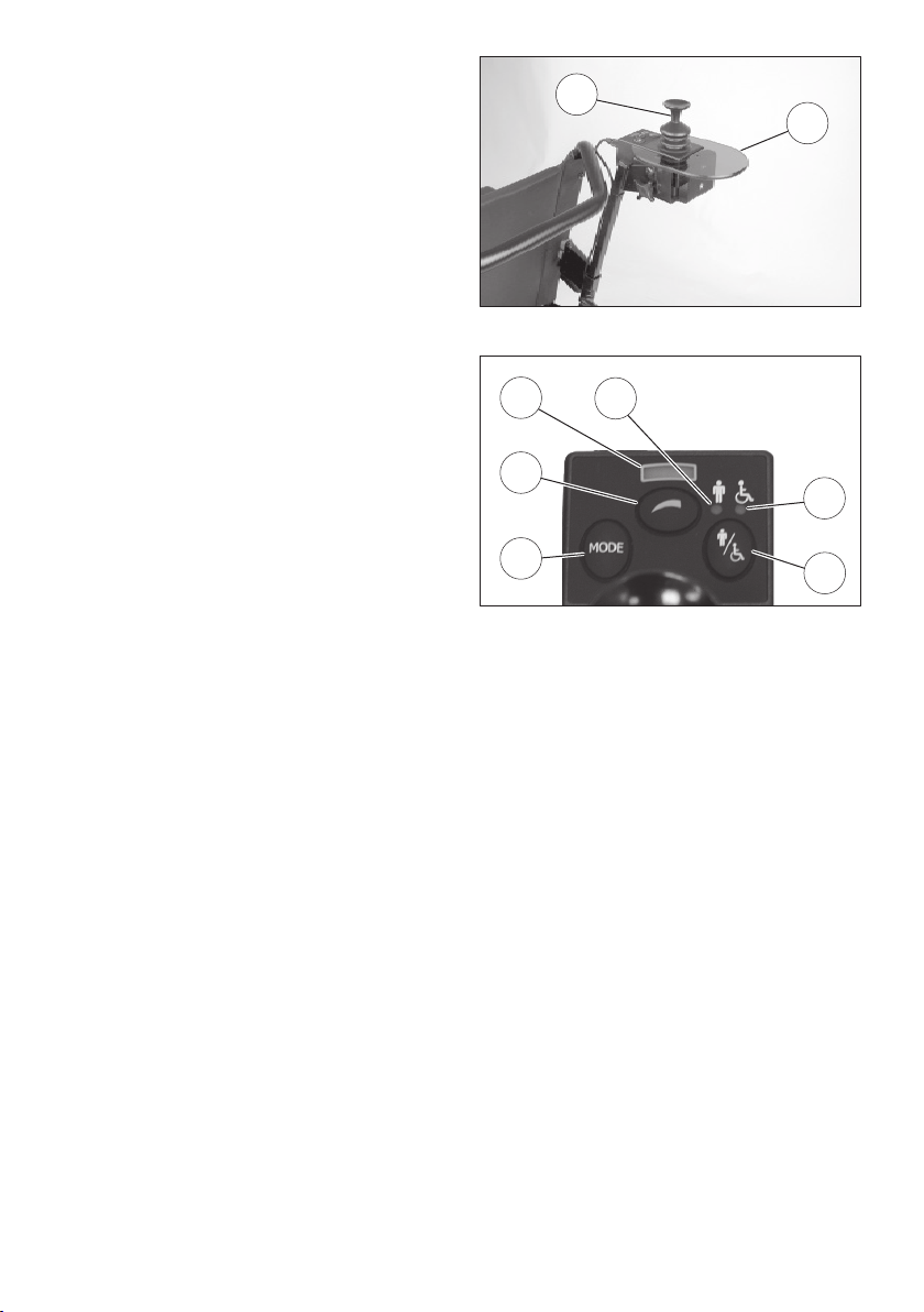
Attendant control
(1) Joystick
(2) Support plate
Push-button control panel
(3) Pre-set maximum speed
(4) Mode selector
(5) Control mode selector (user/attendant)
LED indicators
(6) Control mode (user)
(7) Control mode (attendant)
(8) Pre-set maximum speed levels

11
BUTTONS AND SYMBOLS
ON/OFF Turns the joystick module on and off, respectively.
☞On start-up, the electronics perform a system test.
☞The button automatically returns to a neutral position.
Prole/Mode Cycles through available driving profiles and config-
urable functions each time the lever is moved back-
wards.
☞The Prole/Mode - button must only be pressed when the electric
wheelchair is in a stationary position.
☞Please note the information in chapters Driving program on
page 30 and Mode menu on page 23.
☞The button automatically returns to a neutral position.
Horn An audible tone sounds the entire time the button
remains depressed.
Mode Switches to Settings mode when the button is
pressed.
☞Only press the Mode button when the electric wheelchair is in a sta-
tionary position.
☞Follow the instructions in the chapter Mode menu on page 23.
Prole Switches to the next driving profile when pressed.
☞Follow the instructions in the chapter Driving program on page 30.
Max. speed
setting, Plus
Pushing the knob forward increases the max. speed
setting one level (20%) at a time.
☞We recommend only using the Plus knob when
the electric wheelchair is in a stationary position.
☞Level 1 (20%) up to a max. level of 5 (100%).
☞The knob automatically returns to a neutral position.

12
BUTTONS AND SYMBOLS
Max. speed
setting, Minus
Pushing the knob backwards reduces the max. speed
setting one level (20%) at a time.
☞For safety reasons, we recommend only using
the Minus knob when the wheelchair is in a sta-
tionary position.
☞Level 5 (100%) down to a min. level of 1 (20%).
☞The knob automatically returns to a neutral position.
Hazard light When pressed, turns the hazard light on or off.
☞The symbol flashes in time with the turn signal.
Lights When pressed, turns the lights on or off.
☞The symbol lights up when the lights are on.
Left turn
signal
When pressed, switches the turn signal on or off.
☞A rapidly flashing symbol means that a turn signal is defective.
Right turn
signal
When pressed, switches the turn signal on or off.
☞A rapidly flashing symbol means that a turn signal is defective.
Attendant control
Pre-set speed Pushing the knob increases the max. speed setting
one level (20%) at a time.
☞Level 1 (20%) up to a max. level of 5 (100%).
Display of the
max. speed
The number of illuminated diodes (LEDs) shows the
maximum speed.
☞Each LED corresponds to an additional 20% level.
Control mode Toggles between user and attendant control with
each press of the button.
13
Attendant control
Pre-set
control mode
indicator
The illuminated diode (LED) below the symbol
shows which control mode has been selected.
Mode Switches between Drive mode and Settings mode.
☞Only press the Mode button when the electric wheelchair is in a sta-
tionary position.
☞Follow the instructions in the chapter Mode menu on page 23.
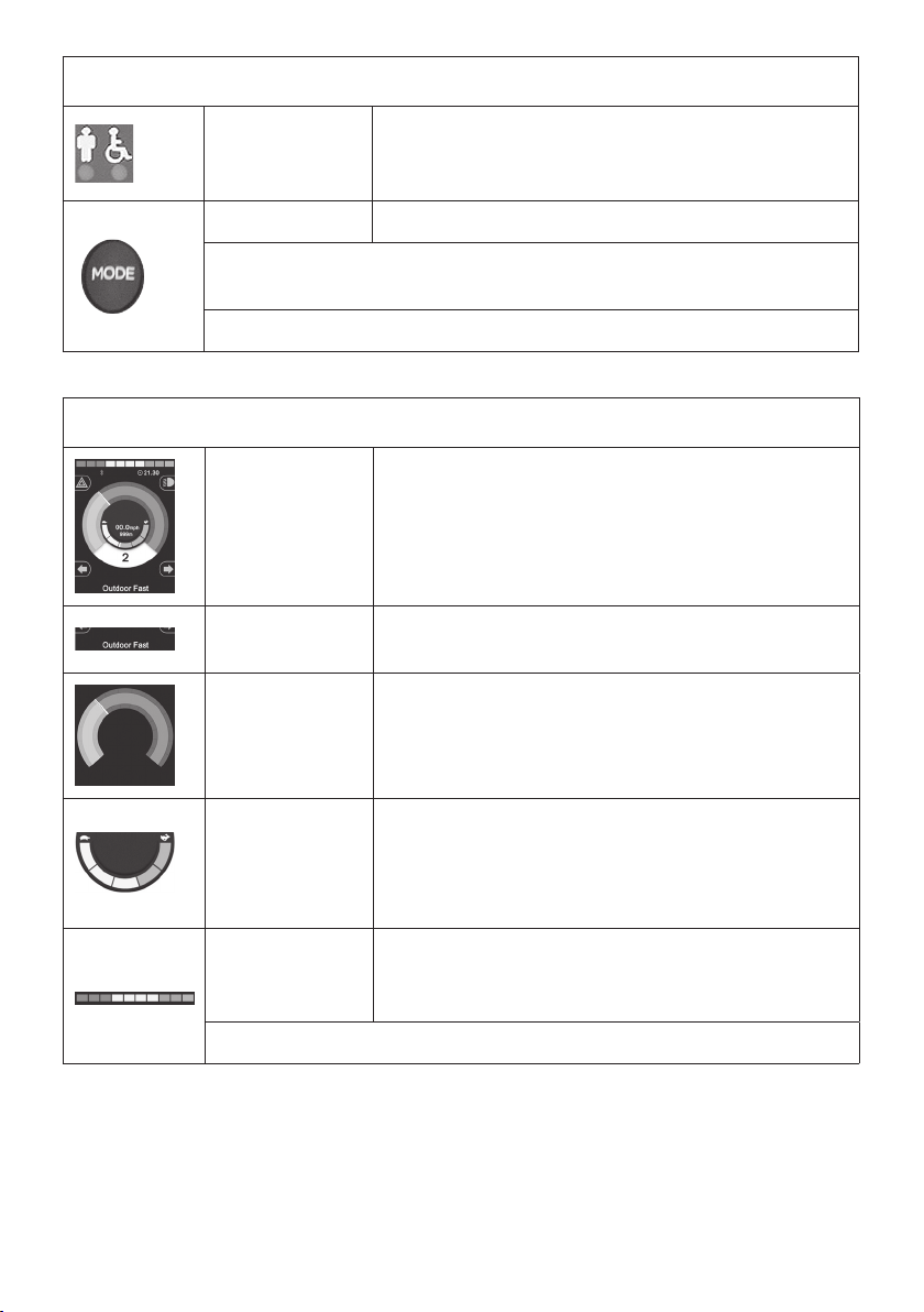
LCD screen
LCD screen When the wheelchair is turned on, various indicators
appear on the LCD display.
Information
box
Displays the selected driving profile.
Speed display The indicator moves to the right of the display in line
with any increase in driving speed or power con-
sumption.
Display of the
max. speed
The number of illuminated segments shows the
maximum speed setting.
☞Each segment corresponds to an additional 20%
level.
Battery
charge
indicator
The number of segments that light up on the battery
indicator decreases in line with the battery’s charge
level.
☞Follow the instructions in the chapter Battery indicator on page 19.

14
LCD screen
Electronic
adjustment
The illuminated area within the symbol indicates
which electronic setting is selected.
☞The symbol appears whenever you switch over to Settings mode.
☞Follow the instructions in the chapter Electronic adjustments on
page 26.
Joystick
module
locked
The electric wheelchair is protected against unau-
thorised use.
☞Follow the instructions in the chapter Lock on page 16.
Standby
mode
This symbol appears momentarily just before the
electric wheelchair goes into automatic standby.
Error
messages
Warning messages about various errors.
☞Follow the instructions in the chapter Troubleshooting on page 37.
Bluetooth The (blue) symbol appears whenever Bluetooth has
been activated.
Speed
reduced
If the symbol is yellow, the wheelchair's speed has
been reduced. This is because the seat lift has been
adjusted higher than 5.5 cm and/or the seat tilt ex-
ceeds 14°. If the symbol is red, the wheelchair's Drive
mode has been disabled.

2
15
21
25
6
15
BEFORE USE
Charging the batteries
Do not insert objects aside from the safe-
ty plug and battery charger plug into the
charging socket. – Risk of a short circuit!
To charge the batteries, first turn off the joy-
stick module, then insert the battery charg-
er plug into the joystick module socket (2).
☞Please also refer to the Electric wheel-
chair operating manual.
Connecting the joystick module
Do not touch or move the joystick dur-
ing the start-up phase (lasts approx. one
second)!
Turn on the joystick module by pushing the
control lever (6) forward to ON/OFF (15). The
electronics will now perform a system test.
☞The control lever automatically returns
to a neutral position.
Once the battery indicator (21) lights up con-
tinuously, the electronics are ready for use.
☞After the control module has been
turned on, if driving profile 8 is dis-
played, it means that the chair is in at-
tendant control mode. You can switch
to the wheelchair user’s joystick mod-
ule by pressing the Proles button.
☞If there is a malfunction, messages will
be displayed on the LCD screen.
☞Follow the instructions in the chap-
ter Troubleshooting on page 37.
Push the control lever (6) forward to ON/
OFF (15). This turns off the wheelchair.

1
6
15
16
Lock
The joystick module is locked if a padlock
symbol appears on the LCD screen [1].
The joystick module can be locked to pro-
tect the electric wheelchair against unau-
thorised use. While this is not configured by
default, your distributor can add this feature
on request.
Activating the lock via the ON/OFF
button
1. With the joystick module connected,
push the control lever (6) forward to
ON/OFF (15) and hold it there until you
hear a short beep.
2. Push the joystick all the way forward
(forward driving) and wait until you
hear a short <beep>.
3. Then pull the joystick all the way back
(reverse) and wait once again until you
hear a short <beep>.
4. Release the joystick.
☞When a prolonged <beeeeep> tone
sounds, it signals that the lock has been
activated.
☞The electric wheelchair is now protect-
ed against unauthorised use.

2
1
6
15
17
The lock key feature
After you turn on the joystick module, plug
the lock key [1] into the charging socket (2).
Remove the lock key plug after you hear a
short <beep>.
☞The electronics disable Drive mode and
are automatically shut down.
Deactivating the lock
Deactivating the lock via the ON/OFF
button
1. Connect the joystick module by push-
ing the control lever (6) forward to ON/
OFF (15).
2. Push the joystick all the way forward
(forward driving) and wait until you
hear a short <beep>.
3. Push the joystick all the way back (re-
verse) and wait once again until you
hear a short <beep>.
4. Release the joystick.
☞When a prolonged <beeeeep> tone
sounds, it signals that the lock has been
deactivated.
The lock key feature
After you turn on the joystick module, plug
the lock key [1] into the charging socket (2).
Remove the lock key plug after you hear a
short <beep>.
☞The lock is now deactivated.

18
Auto-shutdown
To conserve battery power, your electric
wheelchair is equipped with an auto-shut-
down feature.
Unless you move the joystick or press a but-
ton on the control module, the wheelchair
shuts down automatically after the pre-set
timeout period.
☞While this feature is not standard, your
service representative can configure it
and set a timeout period ranging from
1 to 30 minutes.

21
19
PRE-DRIVE INSPECTION
Battery indicator
After you turn on the joystick module, after
a short system test, the battery indicator
(21) displays the battery charge level.
As the batteries drain, the battery indicator
will show an increasingly smaller number of
illuminated segments (21).
☞This indicator is made up of 10 seg-
ments (3 red, 4 yellow/orange and 3
green).
The colour of the segments indicates:
Green The batteries are charged.
☞The battery level corre-
sponds to the number of
green indicators that light
up.
Yellow Recharging is advisable.
Red The batteries are empty. Re-
charge as soon as possible.
☞The battery indicator is only accurate
when travelling on flat surfaces.
☞When driving up or down a gradient,
the reading will be unreliable.
Interpretation
The battery indicator has been designed for
the discharge properties of the manufactur-
er's original batteries. Aftermarket or other
batteries may have divergent properties
that negatively affect the reliability of this
display.
Moreover, since an accurate reading is con-
tingent on the age of the batteries and the
temperature and load to which they are ex-
posed, certain limitations apply.

25
13
20
Pre-set maximum speed
Risk of an accident due to:
– Inappropriately set maximum speed
level.
– Select a lower maximum speed level
while driving!
The max. speed level must be selected
according to your personal circumstances
and particular driving situation!
When driving downhill adjust the max.
speed in proportion to the steepness of
the gradient. Never exceed the maximum
allowable speed. – Risk of an accident!
When you turn on the joystick module, it
automatically recalls and reactivates the last
max. speed setting.
The number of segments that light up in the
max. speed indicator (25) indicates the max.
speed level setting.
☞Follow the instructions in the chapter
Buttons and symbols on page 11.
Before or while driving, moving the control
lever (13) forwards or backwards, respec-
tively, increases or decreases the maximum
speed setting one level at a time.
☞Please see chapters Speed levels on
page 22 and Buttons and symbols on
page 11in this context.
Table of contents
Other Meyra Medical Equipment manuals


Popular Medical Equipment manuals by other brands


LINET
LINET Air2Care 10 Service manual

CENTROBED
CENTROBED ARCTIC quick guide

Bauerfeind
Bauerfeind GloboPed Mobil Instructions for use

PhysioAssist
PhysioAssist SIMEOX User notice

Welch Allyn
Welch Allyn Micro Tymp 2 Service manual

Fresenius Medical Care
Fresenius Medical Care GranuFlo 450385 Operator's manual

Invasix
Invasix InMode Operator's manual

Smiths Medical
Smiths Medical CADD Solis v 3.0 manual

Shenzhen Combei Technology
Shenzhen Combei Technology BP100A instruction manual

Atos Medical
Atos Medical Provox XtraHME Instructions for use

Nutricia
Nutricia Flocare Infinity Short manual

medi
medi protect.Leva Instructions for use