manuals.online logo
Brands
  1. Home
  2. •
  3. Brands
  4. •
  5. Allied Telesis
  6. •
  7. Power Supply
  8. •
  9. Allied Telesis AT-PBPWRDC User manual

Allied Telesis AT-PBPWRDC User manual

Technical Specifications
Input Supply Voltage: 48 V DC, 3A maximum
Power Consumption: 15 watts maximum
Maximum Operating Temperature: ° C to 5 ° C (32° F to 122° F)
Maximum Storage Temperature: -25 °C to 7 °C (-13 °F to 158° F)
Humidity: 5% to 95% maximum (non-condensing)
Electrical Safety: UL 195 , (UL/cUL), EN6 95
Electrical Safety and Emission Statement
Standards: This product meets the following standards.
RFI Emission EN55022 Class A, EN61000-3-2, EN61000-3-3
Warning: In a domestic environment this product may cause radio interferencein which casethe user may be
required to take adequate measures.
Immunity EN55024
Electrical Safety EN60950, UL1950 (UL/cUL)
Copyright  2 Allied Telesyn International, Corp.
All rights reserved. No part of this publication may be reproduced without prior written permission
from Allied Telesyn International, Corp.
Allied Telesyn International Corp.
96 Stewart Drive, Suite B
Sunnyvale, CA 94 85 USA
Tel 1 (4 8) 73 - 95 • Fax 1 (4 8) 736- 1
Visit our web site at: www.alliedtelesyn.co
e
U.S. Federal Communications Commission
RADIATED ENERGY
Note: This equipment has been tested and found to comply with the limits for a Class A digital device pursuant to
Part 15 of FCC Rules. These limits are designed to provide reasonable protection against harmful interference when
the equipment is operated in a commercial environment. This equipment generates, uses, and can radiate radio
frequency energy and, if not installed and used in accordance with this instruction manual, may cause harmful
interference to radio communications. Operation of this equipment in a residential area is likely to cause harmful
interference in which case the user will be required to correct the interference at his own expense.
Note: Modifications or changes not expressly approved of by the manufacturer or the FCC, can void your right to
operate this equipment.
Industry Canada
This Class A digital apparatus meets allrequirements of the Canadian Interference-Causing Equipment Regulations.
Cet appareil numérique de la classe A respecte toutes les exigences du Règlement sur le matériel brouilleur du
Canada.
Overview
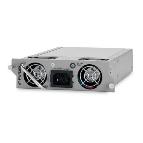
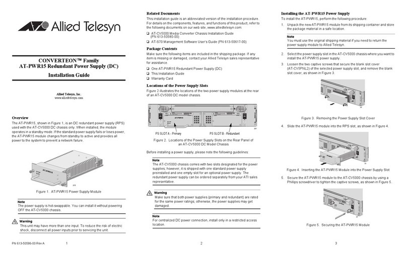
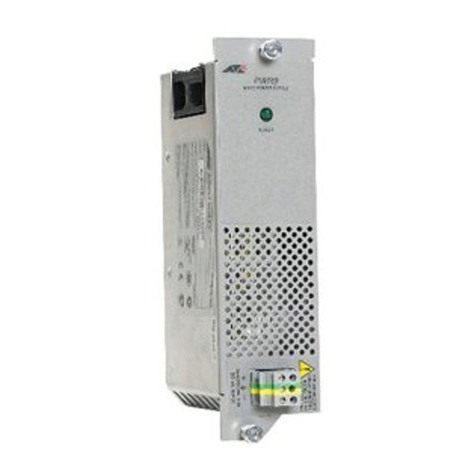
The AT-PBPWRDC is an optional DC power supply for the PowerBlade Chassis. When
installed, the optional power supply shares the load of powering the chassis with the
main power supply. This is known as “load-sharing.” In the event the main power
supply fails, the redundant power supply will provide full power to the chassis, thereby
preventing a system failure.
The main and redundant power supplies can be “hot swapped,” meaning that should
either power supply fail, the failed power supply can be removed and replaced with a
new power module while the chassis is operating. Network operations will not be
interrupted.
Related Documents
This quick install guide is an abbreviated version of the installation procedures. For
complete details on the features, functions and installation instructions, refer to the
PowerBlade Chassis Installation Guide. This guide is available from Allied Telesyn’s
web site at www.alliedtelesyn.com.
Package Contents
Make sure the following items are included in your package. If any of these items are
missing or damaged, contact your Allied Telesyn sales representative.
❑One AT-PBPWRDC Power Supply
❑This quick install guide
❑Warranty card
4PN 613-50189-00 Rev A 010316
AT-PBPWRDC
Optional Redundant Power Supply
Quick Install Guide
For use in a PowerBlade Chassis
Installing an Optional Power Supply
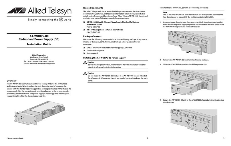
To install an AT-PBPWRDC power supply, perform the following procedures:
1. Remove the blank faceplate covering the PWR2 expansion slot from the back of the
chassis by loosening the two thumbscrews.
2. Remove the power supply from the shipping package and store the packaging
material in a safe place.
3. Slide the optional power supply into the slot, gently seating the power supply’s
connectors into the chassis’ backplane.
4. Secure the optional power supply to the chassis by tightening the two thumbscrews.
Note
It is recommended that you connect the main and redundant power supplies to
power outlets on separate power circuits to protect your chassis from a loss of
power due to a power circuit failure.
5. Before attaching the wires to the DC terminal block on the chassis, review the
following warning:
Warning
As a safety precaution, a 1 Amp circuit breaker should be installed at the supply
end of the cable to be used with this LAN equipment.
ALWAYS connect the wiring to the LAN equipment first before connecting the
wiring to the breaker. To avoid the danger of physical injury from electrical shock,
do not work with HOT feeds. Always be sure that the breaker is in the OFF
position before connecting the wiring to the breaker.
6. Identify the positive, frame ground and negative terminals on the new power
supply using the positive (+), ground ( ), and negative (-) symbols.
7. Strip the three wires in the cable tray coming from the DC input power source to 8
millimeters ± 1 millimeters ( .31 inches ± . 39 inches) using a 14-gauge
wire-stripping tool.
Warning
Do not strip more than the recommended amount of wire. Stripping more than the
recommended amount can create a safety hazard by leaving exposed wire on the
terminal block after installation.
8. Connect the frame ground wire to the terminal marked with the ground symbol by
inserting the wire into the terminal block and tightening the connection with a
flathead screwdriver.
Warning
When installing this equipment, always ensure that the frame ground connection
is installed first and disconnected last.
9. Connect the positive feed wire to the terminal block marked + (positive).
1 . Connect the negative feed wire to the terminal block marked - (negative).
Warning
Safety Hazard - Check to see if there are any exposed copper strands coming
from the installed wires. When this installation is done correctly there should be
no exposed copper wire strands extending from the terminal block. Any exposed
wiring can conduct harmful levels of electricity to persons touching the wires.
11. Secure the tray supply cable near the rack using multiple cable ties (not provided).
This will help minimize the chance of the connections being disturbed by casual
contact with the wiring. It is recommended that you use at least four cable ties 1
centimeters (4 inches) apart with the first one located within 15 centimeters (6
inches) of the terminal block.
Warning
This system will work with a positive grounded or negative grounded DC system.
12. Connect the three DC wires to a DC power source.
13. The Power LED on the module should be green. If the Power LED is OFF, refer to
the PowerBlade Chassis Installation Guide for troubleshooting instructions.
14. The AT-PBPWRDC is now ready for use.
Hot Swapping a Power Supply
The main and optional power supplies are hot swappable. The power supplies to be hot
swapped must be the same type. You cannot install an AC power supply and a DC
power supply in the same chassis.
Warning
When installing this equipment, always ensure that the frame ground connection
is installed first and disconnected last.
1. Remove the positive and negative feed wires from the terminal block on the failed
power supply by loosening the screws to the wire connections with a flathead
screwdriver.
2. Remove the frame ground wire from the terminal block on the failed power supply
by loosening the screw to the wire connection with a flathead screwdriver.
3. Loosen the two thumbscrews and slide out the failed power supply.
4. Remove the new power supply from the shipping package and store the packaging
material in a safe location.
5. Slide the new power supply into the expansion slot, gently seating the power
supply’s connector into the chassis’ backplane.
6. Secure the new power supply to the chassis by tightening the two thumbscrews.
7. Apply power to the new module by repeating Step 5 through Step 12 in the previous
procedure.
8. The Power LED on the module should be green. If the Power LED is OFF, refer to
the PowerBlade Chassis Installation Guide for troubleshooting instructions.
2 3
Other Allied Telesis Power Supply manuals

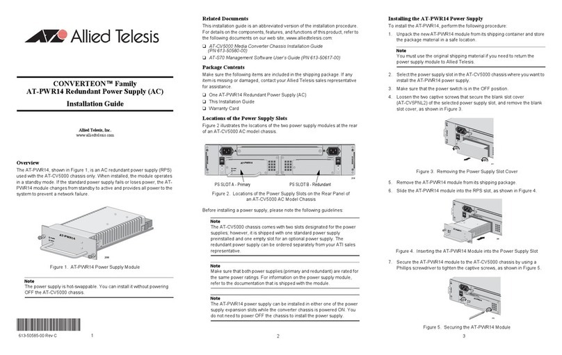
Allied Telesis AT-PWR4 User manual

Allied Telesis

Allied Telesis AT-PWR4 User manual

Allied Telesis AT-BRPS8000 User manual

Allied Telesis

Allied Telesis AT-BRPS8000 User manual

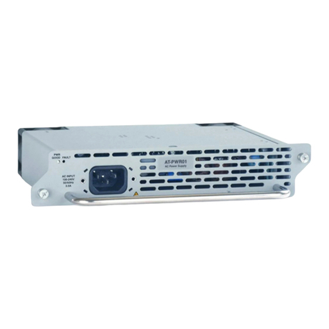
Allied Telesis AT-PWR01 User manual

Allied Telesis

Allied Telesis AT-PWR01 User manual

Allied Telesis AT-RPS3000 User manual

Allied Telesis

Allied Telesis AT-RPS3000 User manual

Allied Telesis AT-RPS9700 User manual

Allied Telesis

Allied Telesis AT-RPS9700 User manual

Allied Telesis AT-PWR3202 User manual

Allied Telesis

Allied Telesis AT-PWR3202 User manual

Allied Telesis SWITCHBLADE 4000 User manual

Allied Telesis

Allied Telesis SWITCHBLADE 4000 User manual

Allied Telesis AT-MCF2000AC User manual

Allied Telesis

Allied Telesis AT-MCF2000AC User manual

Allied Telesis IE048-480 User manual

Allied Telesis

Allied Telesis IE048-480 User manual

Allied Telesis AT-PWR4 User manual

Allied Telesis

Allied Telesis AT-PWR4 User manual

Allied Telesis AT-PWR01 User manual

Allied Telesis

Allied Telesis AT-PWR01 User manual

Allied Telesis AT-PWR11 User manual

Allied Telesis

Allied Telesis AT-PWR11 User manual

Allied Telesis AT-9408LC/SP Series User manual

Allied Telesis

Allied Telesis AT-9408LC/SP Series User manual

Allied Telesis AR740 RPS User manual

Allied Telesis

Allied Telesis AR740 RPS User manual

Allied Telesis AT-RPS3204 User manual

Allied Telesis

Allied Telesis AT-RPS3204 User manual

Allied Telesis AT-RPS3204 User manual

Allied Telesis

Allied Telesis AT-RPS3204 User manual

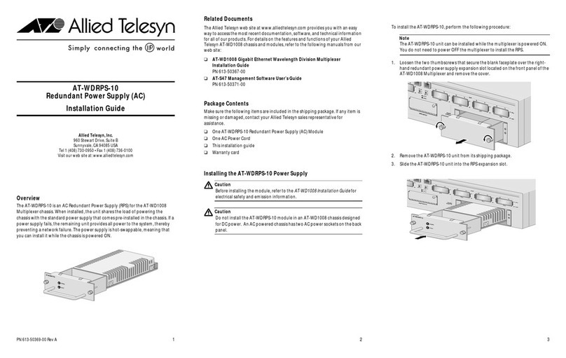
Allied Telesis AT-WDRPS-10 User manual

Allied Telesis

Allied Telesis AT-WDRPS-10 User manual

Allied Telesis AT-PWR9 User manual

Allied Telesis

Allied Telesis AT-PWR9 User manual

Allied Telesis AT-8516F/SC Series User manual

Allied Telesis

Allied Telesis AT-8516F/SC Series User manual

Allied Telesis AT-PWR01 User manual

Allied Telesis

Allied Telesis AT-PWR01 User manual

Allied Telesis CONVERTEON AT-PWR15 User manual

Allied Telesis

Allied Telesis CONVERTEON AT-PWR15 User manual

Allied Telesis AT-FAN01 User manual

Allied Telesis

Allied Telesis AT-FAN01 User manual

Allied Telesis AT-RPS8000 User manual

Allied Telesis

Allied Telesis AT-RPS8000 User manual

Allied Telesis AT-8400 Series User manual

Allied Telesis

Allied Telesis AT-8400 Series User manual

Popular Power Supply manuals by other brands

ELCART Victory-e VIC-75-12 Assembly instructions

ELCART

ELCART Victory-e VIC-75-12 Assembly instructions

Wayne Kerr AP10030 User & service manual

Wayne Kerr

Wayne Kerr AP10030 User & service manual

Spellman XLG SERIES instruction manual

Spellman

Spellman XLG SERIES instruction manual

HP 66312A Programming guide

HP

HP 66312A Programming guide

Cosel TUHS3F instruction manual

Cosel

Cosel TUHS3F instruction manual

GRECELL T500 user manual

GRECELL

GRECELL T500 user manual

Tektronix 1103 instruction manual

Tektronix

Tektronix 1103 instruction manual

Intel ATX12V Design guide

Intel

Intel ATX12V Design guide

ANSMANN APS Series Operation manual

ANSMANN

ANSMANN APS Series Operation manual

Midland enerjump User instructions

Midland

Midland enerjump User instructions

DATATEC KEYSIGHT E36150 Series user guide

DATATEC

DATATEC KEYSIGHT E36150 Series user guide

Ametek Sorensen XTR Series Quick Reference Quide

Ametek

Ametek Sorensen XTR Series Quick Reference Quide

Moxa Technologies DR-75 Series Quick installation guide

Moxa Technologies

Moxa Technologies DR-75 Series Quick installation guide

EGS Appleton JBR Series Instruction for installation and maintenance

EGS

EGS Appleton JBR Series Instruction for installation and maintenance

Rockwell Automation Allen-Bradley 1606-XLE240EC installation instructions

Rockwell Automation

Rockwell Automation Allen-Bradley 1606-XLE240EC installation instructions

Rigol DP900 Series user guide

Rigol

Rigol DP900 Series user guide

Tru-Test 0.04 J user manual

Tru-Test

Tru-Test 0.04 J user manual

Pyramid Gold Series instruction manual

Pyramid

Pyramid Gold Series instruction manual

manuals.online logo
manuals.online logoBrands
  • About & Mission
  • Contact us
  • Privacy Policy
  • Terms and Conditions

Copyright 2025 Manuals.Online. All Rights Reserved.