MFJ Enterprises MFJ-481 User manual


INTRODUCTION
The MFJ-481 GRANDMASTER MEMORY KEYER uses CMOS Integrated Circuit and a Random
Access Memory. It has 1042 bit of memory spaces that will store approximately 100 characters
(two 50 character messages). To insure full benefit of this memory keyer, read this instruction man-
ual before operating.
CONTROL FUNCTIONS
1. SPEED CONTROL: Speed Is approximately variable from 8 to 50 wpm. Turn this control fully
counter clockwise to turn off the memory keyer. CAUTION: All messages stored in the memory
will be erased when this control is turned off.
2. TONE CONTROL: This is an internal adjustment. Remove the top cover by removing the top
two rear screws and slide the top back. Adjust blue trimmer for desired sidetone pitch.
3. VOLUME CONTROL: Adjust the loudness of the sidetone from the internal speaker. This con-
trol is adjustable from the rear panel. Use a small screw driver for this adjustment.
4. RECORD, SEND, REPEAT, TUNE FUNCTION SELECTOR: The RECORD position sets the
memory keyer in the record mode for recording messages into memory. The SEND position al-
lows the memory keyer to send recorded messages and to be used as an electronic keyer. The
REPEAT position allows repeating the recorded message continuously. The TUNE position
keys your transmitter continuously for tuning.
5. MEMORY ADDRESS: Push Buttons A and B are used to directly address memories at the be-
ginning of the message. A and B memories can store up to fifty characters each. Press a MEM-
ORY ADDRESS to start a message.
6. RESET BUTTON: Press to stop memory from operating. When sending a recorded message,
memory can be stopped by pressing the reset button or by tapping the keyer paddle. This re-
sets all memories to the beginning.
7. MEMORY OPERATING LED: Indicates when memory is in operation. LED turns off when
memory is finished.
8. MEMORY SAVER: An internal 9 volts battery (not included, alkaline type recommended)
switches in automatically when a 110 volt AC power failure occurs. This allows all messages to
be retained. A battery clip and holder are provided for installation of a 9 volts battery. If the
sidetone is not used, the MEMORY SAVER has an operation time of approximately twelve
hours. MEMORY SAVER Is also turned off when the keyer is turned off.
INSTALLATION
1. To install the memory saver battery. remove the two screws near the rear top. Slide the cover
toward the back and remove. Connect a 9 volt battery to the battery snap then insert the battery
into the holder. A 9 volt alkaline battery should be used. When the memory saver battery is not
used, cover the battery snap with the plastic tubing supplied to prevent shorting.
2. The MFJ-481 comes with a 110 volt AC adapter. First plug the adapter into the sub miniature
jack on the rear panel and then plug the adapter in the 110 VAC wall socket. It is not necessary
to unplug the AC adapter when the memory keyer is not in use.

3. During portable use when 110 VAC is not available, plug external batteries of 12-15 VDC into
the power jack on the rear panel. The tip of the sub-miniature plug is positive and the sleeve is
ground, for external batteries.
4. A squeeze or single lever key can be used. Squeeze key allows IAMBIC operation. Use a stan-
dard quarter inch stereo phone plug and a two conductor shielded cable or two separately
shielded cables. Tie the shields together and use it for ground. The dot wire should be con-
nected to the ring of the plug, the dash wire to the tip and the shield to ground.
5. A reliable solid state keying circuit allows keying of all grid block, cathode and solid state trans-
mitters. For gird block keying use the "Grid Block" keying output, For cathode keyed and solid
state transmitter. use the "Direct" keying output. Try both outputs if you are uncertain to which
output to use. The keyer outputs are self protected The "Grid Block" output keys a maximum
negative voltage of 300 volts to ground at 10 ma. The "Direct" output keys a maximum positive
voltage of 300 volts to ground at a maximum current of 100 ma. Use a shielded cable to con-
nect between the memory keyer and the transmitter key input.
OPERATION NOTES
1. Shielded cables must be used between the key and the memory keyer jack and between the
keyer output and the transmitter to prevent RF interference.
2. If an unwanted dot should appear at the beginning of a recorded message, press the desired
MEMORY ADDRESS button two or three times in the record mode before programming.
3. Cover the battery snap if memory saver battery is not in use. Use the plastic tubing provided.
4. Use only the MFJ AC adaptor supplied. Do not use more than 15 volts for the external battery.
The tip of the sub-miniature jack is positive and the sleeve is ground.
OPERATION PROCEDURE
I. KEYER OPERATION
1. Apply power to the memory keyer. Use the AC adapter provided.
2. Plug in key paddle to the KEY jack. A dual paddle squeeze key or a single lever key can be
used.
3. Turn Function Switch to SEND position.
4. Turn SPEED control clockwise to turn on memory keyer.
5. Start sending with paddle and adjust volume, tone and speed. The VOLUME control is located
on the rear panel, TONE is an internal adjustment. Remove cover by removing two top ear
screws to make this adjustment.
6. The dot and dash memories ease sending by allowing keying the dot before the completion of
the dash or vice versa. This feature can be checked by setting to the lowest speed and tap first
the dash lever then the dot lever before the completion of the dash. The keyer will provide both
the dash and the dot. The dash memory can be checked by first tapping the dot then the dash.
The dot insertion features allows you to tap the dot side to insert a dot while holding the dash
side in. The dash insertion feature allows you to tap the dash side to insert a dash while holding

the dot side in. When using squeeze key and with both paddles squeezed together, the iambic
operation feature allows sending of alternate dots and dashes. The first contact determines
whether a dot or dash occurs first.
II. MEMORY OPERATION
A. Recording
1. Turn the Selector Switch to the RECORD position.
2. Adjust SPEED control for the desired speed. Press a MEMORY ADDRESS button (A or B) and
start sending immediately. (NOTE; Recording will not start until a MEMORY ADDRESS button
is pressed while in the record mode.) Memory LED will light up when memory is in operation.
Message including spaces is being recorded as long as the LED is lit in the record mode. When
LED goes out, this indicates the memory is full. If LED goes out before sending is completed,
the message Is too long. When recording, the internal clock runs continuously to allow spaces
of any length to be entered into the memory; thus, there is a random delay from zero to the
length of one dot. This requires you to synchronize your sending with the keyer to some extent.
At low speed (10-15 wpm) dots may even be missed occasionally. This can be avoided by not
releasing the dot lever until a dot starts.
3. Occasionally, an unwanted dot may appear in the beginning of a recorded message: this is due
to improper erasing. To insure a complete erasure of previously recorded message in the mem-
ory when recording it is best to press he address button two or three times before sending.
Note that the MEMORY ADDRESS, when pressed, resets the memory to the beginning of that
address either record or play mode; therefore, the reset button need not be pressed when pro-
gramming. A recorded message can also be corrected by first playing the correct part of the
message and just before the mistake turn to record mode to complete recording the message.
NOTE: The memory keyer will key the transmitter in the record mode. It must be disconnected
from the transmitter during recording. The transmitter may also be disabled by switching the
transmit/receive switch to the receive mode.
B. Play Back
1. Turn the Function Switch to SEND. This puts the memory keyer in the play mode. Press the de-
sired MEMORY ADDRESS button.
2. The LED indicates memory is in operation. MEMORY ADDRESS resets message to the begin-
ning once it is pressed.
3. To interrupt a playing message or to make an insertion, simply send at the point where changes
are to be made. The message can be continued by pressing another MEMORY ADDRESS but-
ton which contains the remainder of the message.
4. To repeat, turn the function Switch to the REPEAT Position, then press the same MEMORY
ADDRESS button. The recorded message will repeat continuously until it is Interrupted. NOTE:
The repeat function will repeat both messages and any length of space at the end of a mes-
sage. Recording a pause at the end of a message will allow you to listen before the message is
repeated again.
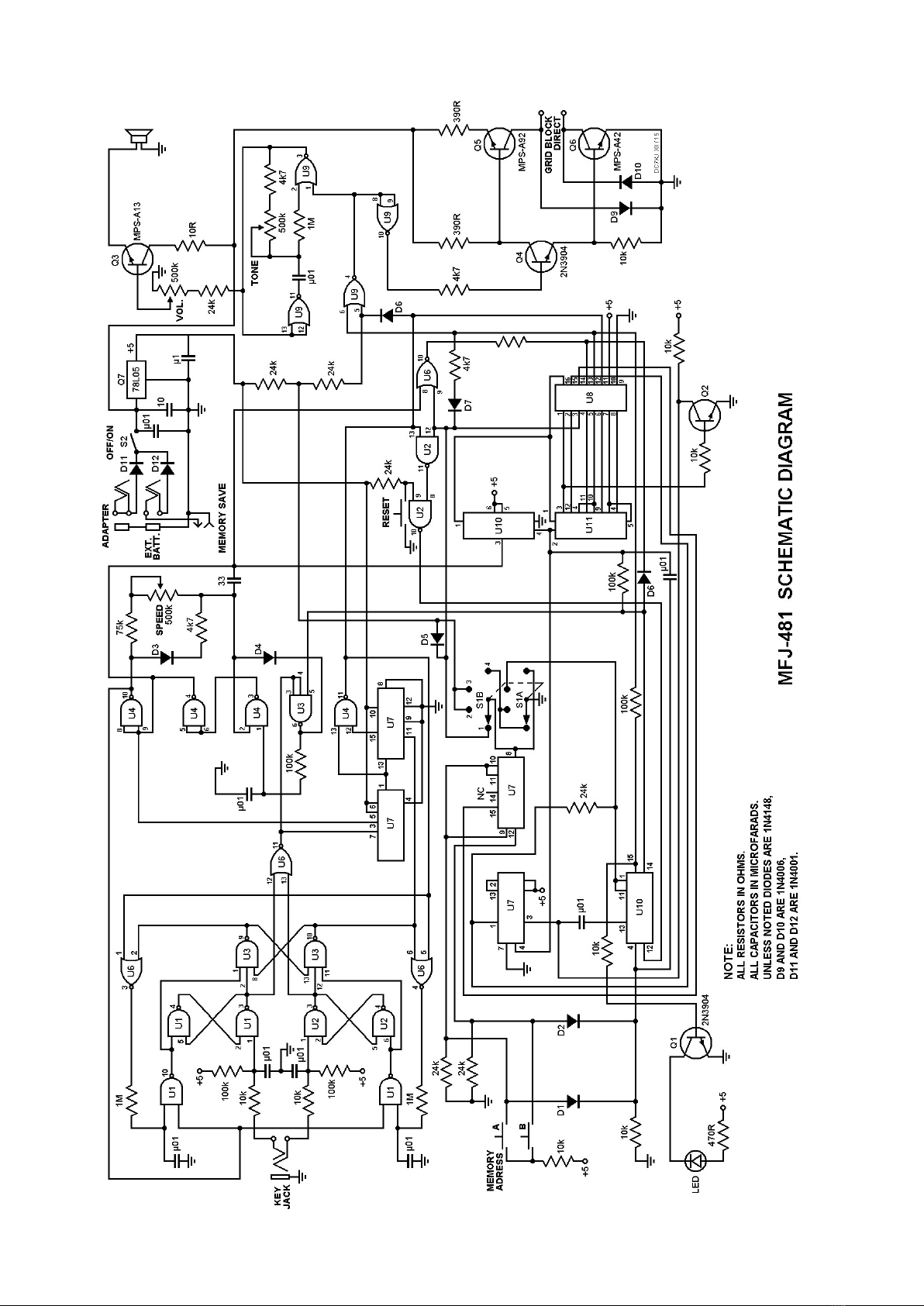
Reprint: DC7XJ – XII.2015

MFJ-481 COMPONENTS LOCATION DIAGRAM

Table of contents
Other MFJ Enterprises Radio manuals