MFJ MFJ-1795W User manual

INSTRUCTION MANUAL
CAUTION: Read All Instructions Before Operating Equipment
MFJ ENTERPRISES, INC.
300 Industrial Park Road
Starkville, MS 39759 USA
Tel: 662-323-5869 Fax: 662-323-6551
COPYRIGHT 2006 MFJ ENTERPRISES, INC.
C
Model MFJ-1795W
VERSION 1A
WARC Band Portable Antenna

MFJ-1795W Vertical Antenna Instruction Manual
60 Meter
Capacitance Spokes (8)
& Loading Coil
30 Meter (4)
17 Meter (4)
12 Meter (4)
Note: This drawing is not to scale
MFJ-1795W
WARC Band
Vertical Antenna
Always
Follow
Assembly
Instructions!!
Mount
Mounting Bracket
1” x 30”
30 x 1” Tubing
5’ x1 1/8” Tubing
WARC Bands Vertical Antenna
1

MFJ-1795W Vertical Antenna Instruction Manual
INTRODUCTION
The MFJ-1795W HF antenna was designed to provide portable or permanent WARC Band
operation from restricted locations. When combined with the MFJ Ground-Coupled™ Portable
Antenna Base or other suitable grounding system, such as radial system, the result is a small
vertical antenna under 10 feet in height.
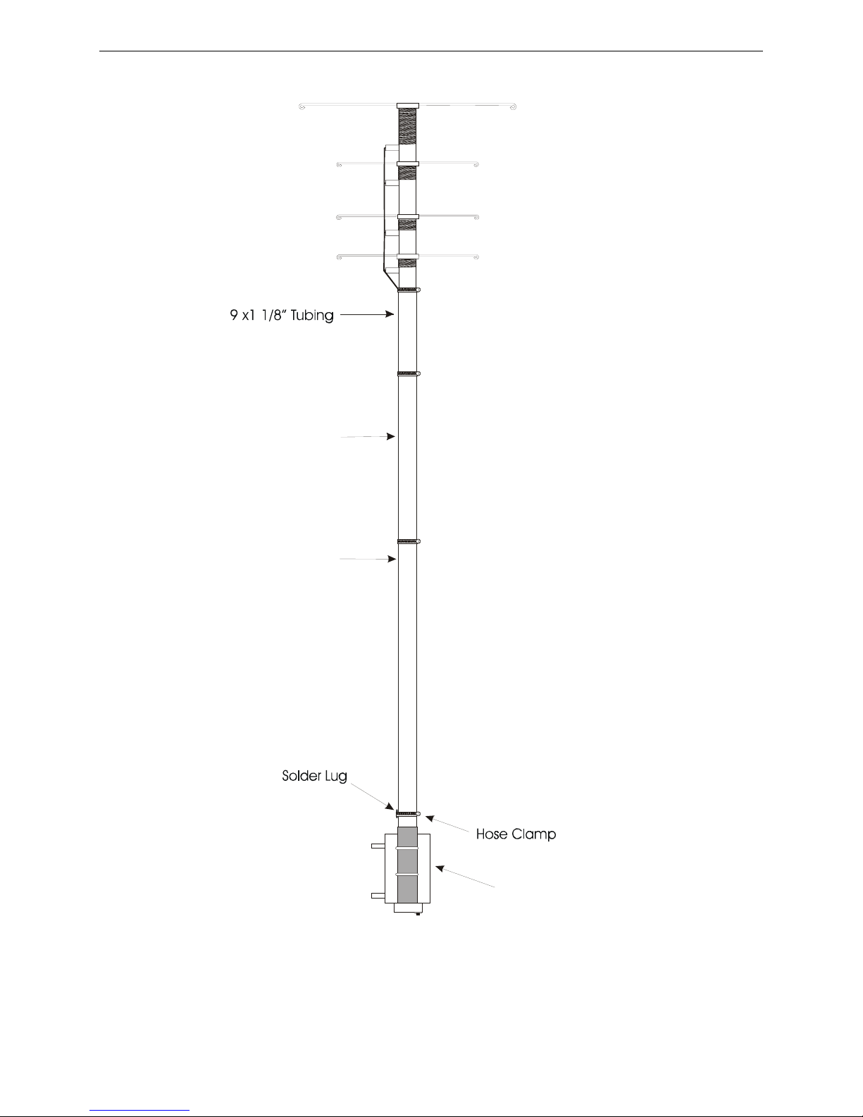
The reduction in size is accomplished by adding separate loading coils and capacitance hats for
each band at the top of the antenna. The efficient end loading coils are wound on fiberglass
forms. The high quality materials and construction of the HF loading system allows a maximum
power rating of 1500 watts SSB PEP on 60, 30, 17 and 12 meters.
The power rating of this antenna varies from band to band. The PEP ratings are primarily
determined by the voltage breakdown of the components, while the CW ratings are generally
determined by the components heating.
The following chart lists the power rating and the 2:1 VSWR bandwidth of this antenna:
Band (Meters) Power (Watts) Bandwidth (KHz)
CW SSB RTTY
60m 700 1500 500 100
30m 1250 1500 750 300
17m 1250 1500 1000 1000
12m 1250 1500 750 2000
The weight and wind load of this antenna are 10 pounds and approximately two square feet
respectively.
WARNING: Improper installation and assembly can be hazardous! Read
these instructions thoroughly before attempting to assemble, install, or
operate this product! High power transmitting devices produce voltages that
can cause severe burns or other injuries.
CHOOSING A LOCATION FOR THE ANTENNA
The best performance on receiving and transmitting will be obtained by mounting the antenna in
a clear location above or away from buildings, towers, feed-lines, utility wires, and other
antennas. While your own ingenuity and particular circumstances will determine the final
mounting method, we will pass along a few ideas for both permanent and portable installation.
WARNING: Always mount this antenna so that it is out of the reach of adults as well as
children. The capacitance elements can cause injury and or severe RF burns.
2

MFJ-1795W Vertical Antenna Instruction Manual
•Never place this antenna in a location that will permit people to encounter the loading
spokes or any other part of the antenna.
•Never place this antenna where a mechanical failure might allow the antenna to contact
power lines or other utility wires.
•Always ground the feed-line at the point where it enters a building to a good earth ground
for lightning protection.
•Follow the guidelines for antenna installations as recommended by the US consumer
product safety commission.
ANTENNA HEIGHT
The height of the radiating element is adjustable from 5 to 8 feet. Maximum radiation will be
obtained by setting the height of the radiating element at 8 feet. Some installations may require
the antenna height to be reduced. An example may be the installation of the antenna inside a
backyard fence for concealment. Height adjustment will be discussed in the assembly section of
this manual.
INSTALLATION
The MFJ-1795W was designed as a low profile, portable antenna. When combined with the MFJ
Ground-Coupled™ Portable Antenna Base the antenna will provide permanent or portable
communications. This is an ideal antenna for restricted locations. However, the antenna
installation MUST be protected with non-metallic fencing to provide personal safety and to
prevent antenna damage. The antenna can be installed using the supplied mounting bracket and
a suitable ground radial system.
IMPORTANT:A suitable ground plane must be installed with this antenna.
PORTABLE SETUP
The antenna may be disassembled to the extent necessary for transporting to a temporary
location. Before the antenna is disassembled, some type of marks should be placed on the mast
of the antenna to ensure it will be the same height as before. Some retuning may be required
after moving the antenna.
WARNING: If the antenna falls it will be damaged and may cause serious injury.
Whatever type of installation you choose, remember that the antenna should be installed
where it can never be contacted by people or animals.
TOOLS AND TIME REQUIRED FOR ASSEMBLY
3

MFJ-1795W Vertical Antenna Instruction Manual
The estimated assembly time for this antenna is 1 hour. Antenna assembly requires the following
hand tools:
[ ] soldering iron and solder
[ ] 5/16" nut driver (or 1/4" flathead screwdriver)
[ ] 7/16" open end wrench
[ ] Heavy wire cutters for trimming capacitance spokes
[ ] small pliers
[ ] #1 phillips screwdriver
[ ] #2 phillips screwdriver
[ ] suitable eye protection
In addition, you will need two stable supports at least 30" tall (i.e. saw horses or trash cans) and
a short (6 to 8 feet) temporary mast (1 to 1-1/2 inches outside diameter) for temporary mounting
during tuning.
MFJ-1795W PARTS LIST
As you unpack your antenna you should find the parts in the following list.
[ ] two (2) bundles of wire capacitance spokes eight (8) 21” spokes, and 14 36” spokes, and two
(2) spare 21” spokes.
[ ] 5' radiator 1 1/8"
[ ] 30”x 1” radiator
[ ] 9”x 1 1/8” radiator
[ ] loading coil assembly
[ ] base mounting bracket
[ ] hollow fiberglass rod insulator
[ ] One Hardware Bag containing
[ ] 4 1.5” hose clamps
[ ] bag of short 6-32 stainless screws
[ ] bag of 6-32 stainless kep nuts
[ ] bag of 1/8" plastic spoke caps
[ ] 4 U-bolts with hardware
[ ] two plastic tie wraps
[ ] 2 solder lugs
For installation you will need some additional items not supplied with the antenna installation
kit.
[ ] Quality low-loss 50-Ohm coax with a PL-259 to go from the antenna to the transmitter.
[ ] Either a SWR meter or Analyzer (MFJ-259B, 269)
SAFETY PRECAUTIONS:
4

MFJ-1795W Vertical Antenna Instruction Manual
WARNING: You can be killed if the antenna, feed-line, or the equipment used to install
the antenna accidentally contacts any utility lines. Never install an antenna near power
lines!
1. Be careful while carrying the antenna. It is heavy enough to cause you to lose your balance if
it is handled too casually or if the capacitance spokes become entangled in obstructions.
2. Mount the antenna in a way so that it is out of reach. The ends of the capacitance spokes can
cause eye injury, serious RF burns or both.
3. Make sure that a mast, if used, is sturdy enough to support the weight and the wind load.
ASSEMBLY AND INSTALLATION PROCEDURE
During assembly of this antenna refer to the figures in this manual and the picture on Page 1.
NOTE: Wear safety glasses whenever working on or near this antenna.
Do not tighten the screws that connect the loading coil terminal lugs to the capacitance hats or
you will BREAK the fiberglass form. If the terminal lugs loosen tighten the NUT on the lug.
STEP-BY-STEP PROCEDURE
[ ] 1. Prepare a temporary work surface, such as a table, two saw horses, or trash cans, to be
used while installing the parts onto the antenna.
[ ] 2. Sort out the parts you have unpacked into groups of similar parts. Be sure all the parts are
available.
[ ] 3. After examining the antenna parts, gather the tools needed for basic assembly. At the
minimum these consist of:
[]#1 Long Phillips screwdriver for capacitance spoke screws
[]1/4" flathead screwdriver or a 5/16" nut driver for hose clamps.
[]Two 7/16" open end wrenches or one wrench and one nut driver for the U-bolts.
[]Heavy Wire cutters for trimming capacitance spokes.
[]Safety glasses.
[ ] 4. Decide on the approximate height of the antenna. Maximum height will be just under 10
feet while minimum will be 6 1/2 feet. The antenna will operate best at a height of 10
feet.
[ ] 5. The 6 1/2 foot level can be reached by using the 5’ radiator. If this is the desired height
steps 6-8 may be skipped. Heights above this level will be reached using the additional
pieces of tubing.
5

MFJ-1795W Vertical Antenna Instruction Manual
[ ] 6. Now take the 1.0” x 30” piece of aluminum and place at a minimum 2 inches into the
long aluminum element (5’ x 1 1/8”). The end of the long (5’) piece used should be the
one without the hole drilled in it. See Figure 1.
[ ] 7. A hose clamp should be placed around the 1 1/8” pipe to secure it in place. Tighten it
with the 5/16” nut driver.
[ ] 8. A minimum of 2 inches of the 9” x 1 1/8” pipe should be placed onto the 1.0” x 30” piece
of aluminum and secured with a hose clamp.
Figure 1
NOTE: The length of tubing placed inside 1 1/8” tubing will determine the overall height of
the antenna.
[ ] 9. Now the hollow fiberglass insulator should be placed approximately 3 1/2” into the 60” x
1 1/8” aluminum tubing. See Figure 2.
Fiberglass Insulator
Solder Lug
60 x 1 1/8 Mast Pipe
Antenna Feed Point
Hose Clamp
Figure 2
[ ] 10. Place one of the hose clamps around the aluminum tubing and snug the clamp using a
5/16” nut driver . The center conductor of the coax will be connected to the antenna using
a solder lug placed under the clamp. Refer to figure 2.
[ ] 11.Place one of the small plastic spoke caps from the parts bag onto the end of each of the
capacitance spokes.
[ ] 12. Install the short 6/32” screws in the rings of the loading coil assemblies and place a 6/32”
nut on each screw. Place eight (8) of the 36” capacitance spokes into the eight holes on
the top rings of the loading coil assembly (60M). Then, tighten the screws until the spokes
are snug. Now you should be able to turn the coil assembly over and they should balance
on the long spokes. See Figure 3 and Figure 4.
6

MFJ-1795W Vertical Antenna Instruction Manual
6-32” screw
Loading Coil Assembly
Figure 3
IMPORTANT: Do not use a high torque electric screwdriver to mount the capacitance
spokes. The screw heads will be sheared off if too much torque is applied.
[ ] 13. Install four 36” capacitance spokes in the next sets of rings (30M). Again, tighten these
spokes as was done in step 9. (See Figure 3 and Figure 4)
[ ] 14. Install four 21” capacitance spokes in the remaining two sets of rings (17/12M). Again,
tighten these spokes as was done in step 9. (See Figure 3 and Figure 4)
[ ] 15. Slide a hose clamp over the top radiator. Mount the top coil assembly to the antenna by
inserting the fiberglass insulator in the top radiator. Tighten the metal strap from the coil
assembly under the hose clamp. See Figure 4.
7

MFJ-1795W Vertical Antenna Instruction Manual
Loading Assembly
60 m 30 m 17 m 12 m
Hose Clamp
Figure 4
[ ] 16. Double check the tightness of all the hardware you installed. Then, mount the antenna on
the short temporary tuning mast or the MFJ Ground Coupled Portable Antenna Base.
[ ] 17. Secure the mounting bracket to the fiberglass insulator as shown in Figure 5. Make sure
the antenna mast does not contact the U-bolts. The next four steps may be skipped if the
antenna uses the MFJ-1904 Antenna Base.
Figure 5
8

MFJ-1795W Vertical Antenna Instruction Manual
[ ] 18. Ground radials should be attached to the U-bolts on the Base Mounting Bracket.
[ ] 19. The antenna should be fed using a good quality 50-Ohm low-loss coax such as RG-8 or
RG-58. Approximately 4 inches of the outer insulation should be removed. The center
conductor of the coax should be soldered to the solder lug that was placed on the ¼” bolt
in step 10 of the assembly. The outer shield of the coax should be soldered to the
additional solder lug supplied in the parts bag. Place this solder lug onto one of the U-
bolts located on the mounting bracket Secure it using one of the ¼ “nuts supplied with the
U-bolts.
WARNING: Serious burns can be received with improper use of a soldering iron.
[ ] 20. Tune the antenna by following the instructions under the section “Frequency and SWR
Adjustment”.
[ ] 21. Mount the antenna in its permanent location. Slight retuning and height adjustment may
be necessary.
USING THE MFJ GROUND-COUPLED™ PORTABLE ANTENNA BASE WITH THE
MFJ-1795W
The antenna base should be assembled using the instructions supplied with the unit. The
following instructions will explain the installation of the MFJ-1795W to the antenna base.
[ ] 1. The U-bolts should be attached to the base through the holes as indicated in Figure 5.
[ ] 2. The SO-239 connecter, supplied with the base, should then be installed on the top of the
base plate mount as indicated in Figure 6 using two 6/32” x 3/8” screws and kep nuts
supplied with the base. One of the feed-points at the bottom of the base may also be used.
The insulated wire supplied with the MFJ-1904 will be long enough for this application.
This will increase the radiating length of the antenna.
9

MFJ-1795W Vertical Antenna Instruction Manual
Figure 6
U-bolts
Bushing
SO-239
Anetnna Base
[ ] 3. The plastic bushing supplied in the parts should be placed in the hole under the SO-239
connector.
[ ] 4. Now the 15” piece of insulated wire should be passed through the plastic bushing to the
antenna feed-point.
SO-239
Bus Wire
Figure 7
10

MFJ-1795W Vertical Antenna Instruction Manual
WARNING: Serious burns can be received with improper use of a soldering iron.
[ ] 5. The wire should now be soldered to the center pin of the SO-239 connecter.
[ ] 6. Remove the fiberglass tubing from the aluminum tubing of the assembled antenna by
loosening the hose clamp. Place the solder lug, under the hose clamp and retighten.
[ ] 7. Insert the fiberglass tubing through the U-bolts and tighten the nuts. This will make base
installation much easier.
[ ] 8. Adjust the wire length so that it approaches the soldering lug at the antenna feed-point.
[ ] 9. Carefully solder the insulated wire to the solder lug.
[ ] 10. Tighten the nuts on the U-bolts firmly.
[ ] 11. Re-attach the antenna to the fiberglass tubing by tightening the hose clamp. Remember to
place the solder lug attached to the center conductor of the coax under the hose clamp
[ ] 12. Make sure that the aluminum tubing, the insulated wire, and solder lugs DO NOT COME
INTO CONTACT WITH THE ANTENNA BASE. Small readjustments of the
fiberglass insulator may be necessary.
REMOVING THE ANTENNA FROM THE BASE OR BRACKET
The antenna may be quickly removed to be hidden from view. This is easily accomplished by
loosening the hose clamp at the base of the antenna shown in Figure 2. Carefully pick up the
antenna mast. Be sure to watch for overhead tree limbs and other objects that could come into
contact with the antenna during removal. These objects could cause the antenna to become
unbalanced and fall, resulting in personal injury and damage to the antenna. Store the antenna in
a safe place to prevent damage.
FREQUENCY AND SWR ADJUSTMENT
This antenna covers wider frequency ranges on the higher bands, and narrower segments on the
lower frequency bands. The 60-meter band has the narrowest range of operation (approximately
100 KHz) and is the most sensitive to adjustments.
The entire antenna must be accessible during initial tuning and testing. If the MFJ Ground
Coupled™ Portable Antenna Base is used, attach the antenna to the base and place it in a
location away from buildings or other objects that could affect the measurements. If the portable
antenna base is not used, it is best to install the antenna on a short, temporary mast or pipe.
IMPORTANT: A suitable Ground radial system must be connected to the antenna
mounting bracket if the Ground Coupled Portable™ Antenna Base is not used.
11

MFJ-1795W Vertical Antenna Instruction Manual
The SWR can be measured by using a transmitter and SWR bridge or an SWR Analyzer. The
measuring device should be connected to the antenna with a reasonably short length of high
quality 50-Ohm coaxial cable. If using a transceiver and SWR meter, set the transceiver to the
lowest possible power to take measurements.
Please read the following hints:
• The normal resonant frequency of this antenna is at or below the bottom of each
amateur band. This allows the user to "trim" a small amount off the inside end of the
capacitance spokes to raise the resonant frequency. Conversely, adding a longer capacitance
spoke will lower the resonant frequency of a loading assembly. Spare spokes are included in
case you need to lower the resonant frequency of the antenna.
• If the suspected resonant frequency is lower than your equipment can detect, for
example below 5.0 MHz, take one 60 meter spoke entirely off the antenna. Measure the
resonant frequency again. If the resonant frequency still cannot be found, check another
band. If none of these tests results in a good SWR on any frequency, substitute a 50-Ohm
load for the antenna to test the feed line. If the SWR checks good, the antenna assembly will
have to be checked for proper assembly, shorts, or openings at the feed point of the antenna.
• If the antenna operates normally higher than the band after one spoke is removed,
install all the spokes and trim each spoke in 1/4 inch increments. The spokes for each band
should be cut to the same length.
• Once the resonant frequency is found, use the chart located under the section Tuning The
Antenna section of this manual to estimate the amount of the spoke length to cut so that the
antenna will resonate at your favorite section of the band.
CAUTION: Always start tuning on 60 meters and adjust each band progressively higher in
frequency. Adjustment of a lower frequency band will always have the most effect on the next
higher frequency band. The tendency of the interaction is that if you move one band higher ALL
the other bands move higher, but only very slightly. It is always best to "shoot for" the lowest
end of the range you intend to use, and "trim in" by adjusting the bottom loading assembly after
the antenna is in it's final location. ALWAYS work from the bottom band up.
Tuning the Antenna
1. Measure and record the frequency where the lowest SWR occurs on for each band. The lowest
SWR should be at or below the bottom end of each HF band. The SWR should be below 2:1 at
resonance on each band.
2. The following is a typical chart for initial measurements of a new antenna before tuning:
60 M 1.5:1 at 5.0 MHz
30 M 1.3:1 at 9.7 MHz
17 M 1.2:1 at 17.0 MHz
12 M 1.1:1 at 23.6 MHz
If the resonant frequency is lower than what your equipment detected, take one spoke off to raise
the resonant frequency. Measure the resonant frequency and calculate the approximate resonant
frequency as if the spoke was in place using the chart on the below.
12

MFJ-1795W Vertical Antenna Instruction Manual
CAUTION: Be careful when working with the capacitance spokes. Contact with the sharp
ends could result in injury or damage. When shortening the capacitance spokes
be certain to replace the protective caps after each adjustment.
IMPORTANT: Due to the sensitivity of the resonant frequency on this antenna, small
increments, such as 1/4 inch, should be considered when cutting the spokes to find the
resonant frequency.
Begin tuning by trimming one 60-meter spoke by cutting off small, equal sections from the end
of the spoke. Replace the small protective caps on the ends of the spokes each time you adjust
the length. Continue adjusting until the antenna resonates approximately 15 KHz below the
desired operating frequency. Use the chart below to approximate the amount of spoke to be
trimmed. Trimming only one spoke from the top or bottom results in half the frequency change.
60 M: 1" trimmed off each of the spokes equals approximately 150 KHz
30 M: 1" trimmed off each of the spokes equals approximately 500 KHz
17 M: 1" trimmed off each of the spokes equals approximately 560 KHz
12 M: 1" trimmed off each of the spokes equals approximately 570 KHz
3. Now tune progressively higher frequency bands by trimming the spokes. Keep each set of
capacitance spokes equal in size. 30 meters must be the second HF band adjusted, 17 the third
and 12 meters last. After adjusting 12 meters go back and check the other bands. Tighten all
spoke screws.
GROUNDING CONSIDERATIONS
SAFETY GROUNDING MUST be provided to protect equipment, property, and persons from
the hazards of lighting strikes and other weather related electrical discharges. In addition the
coaxial cable feeding the antenna should have the shield grounded to eliminate the risk of any
indoor equipment failure that would allow hazardous voltages to appear indoors creating a shock
hazard.
Adequate protection can be accomplished by grounding the shield of the coax to a good earth
ground where it enters the building to, or directly burying the cable in several feet of earth before
it enters the building. The coaxial cable should be totally disconnected from the station during
threatening weather conditions for MAXIMUM LIGHTENING PROTECTION.
13

MFJ-1795W Vertical Antenna Instruction Manual
MAINTENANCE
This antenna is constructed of heavy-duty non-corrosive materials and should withstand normal
climates for many years. The use of some type of coaxial connector moisture protection is
recommended at the bottom coax connection, especially in coastal areas where salty mist is
commonplace.
TECHNICAL ASSISTANCE
If you have any problem with this unit first check the appropriate section of this manual. If the
manual does not reference your problem or your problem is not solved by reading the manual,
you may call MFJ Technical Service at 662-323-0549 or the MFJ Factory at 662-323-5869. You
will be best helped if you have your unit, manual and all information on your station handy so
you can answer any questions the technicians may ask.
You can also send questions by mail to MFJ Enterprises, Inc., 300 Industrial Park Road,
Starkville, MS 39759; by Facsimile to 662-323-6551; or by email to
exactly how you are using your unit, and a complete description of your station.
14

MFJ-1795W Vertical Antenna Instruction Manual
FULL 12-MONTH WARRANTY
MFJ Enterprises, Inc. warrants to the original owner of this product, if manufactured by MFJ Enterprises,
Inc. and purchased from an authorized dealer or directly from MFJ Enterprises, Inc. to be free from
defects in material and workmanship for a period of 12 months from date of purchase provided the
following terms of this warranty are satisfied.
1. The purchaser must retain the dated proof-of-purchase (bill of sale, canceled check, credit
card or money order receipt, etc.) describing the product to establish the validity of the warranty
claim and submit the original or machine reproduction of such proof of purchase to MFJ
Enterprises, Inc. at the time of warranty service. MFJ Enterprises, Inc. shall have the discretion to
deny warranty without dated proof-of-purchase. Any evidence of alteration, erasure, of forgery
shall be cause to void any and all warranty terms immediately.
2. MFJ Enterprises, Inc. agrees to repair or replace at MFJ's option without charge to the
original owner any defective product provided the product is returned postage prepaid to MFJ
Enterprises, Inc. with a personal check, cashiers check, or money order for $10.00 covering
postage and handling.
3. MFJ Enterprises, Inc. will supply replacement parts free of charge for any MFJ product
under warranty upon request. A dated proof of purchase and a $8.00 personal check, cashiers
check, or money order must be provided to cover postage and handling.
4. This warranty is NOT void for owners who attempt to repair defective units. Technical
consultation is available by calling (662) 323-5869.
5. This warranty does not apply to kits sold by or manufactured by MFJ Enterprises, Inc.
6. Wired and tested PC board products are covered by this warranty provided only the
wired and tested PC board product is returned. Wired and tested PC boards installed in the
owner's cabinet or connected to switches, jacks, or cables, etc. sent to MFJ Enterprises, Inc. will be
returned at the owner's expense unrepaired.
7. Under no circumstances is MFJ Enterprises, Inc. liable for consequential damages to
person or property by the use of any MFJ products.
8. Out-of-Warranty Service: MFJ Enterprises, Inc. will repair any out-of-warranty product
provided the unit is shipped prepaid. All repaired units will be shipped COD to the owner. Repair
charges will be added to the COD fee unless other arrangements are made.
9. This warranty is given in lieu of any other warranty expressed or implied.
10. MFJ Enterprises, Inc. reserves the right to make changes or improvements in design or
manufacture without incurring any obligation to install such changes upon any of the products
previously manufactured.
11. All MFJ products to be serviced in-warranty or out-of-warranty should be addressed to
MFJ Enterprises, Inc., 300 Industrial Park Rd, Starkville, Mississippi 39759, USA and must
be accompanied by a letter describing the problem in detail along with a copy of your dated proof-
of-purchase and a telephone number.
12. This warranty gives you specific rights, and you may also have other rights, which vary
from state to state.
15
Table of contents
Other MFJ Antenna manuals
Popular Antenna manuals by other brands

MFJ Enterprises
MFJ Enterprises MFJ-1754 instructions

M2 Antenna Systems
M2 Antenna Systems 35.7-4 Assembly manual

Ubiquiti
Ubiquiti RocketDish RD-5G30 quick start guide

Mobile TV
Mobile TV CAPTURE XPLATE Installation and use manual

Capsat
Capsat TT-3005M installation manual

COBHAM
COBHAM SAILOR 100 GX Technical manual