MFJ MFJ-1272B User manual

MFJ-56A/B/C Mailbox Memory / Pactor Expansion
i
Table of Contents
MFJ-56 A/B/C...................................................................................................2
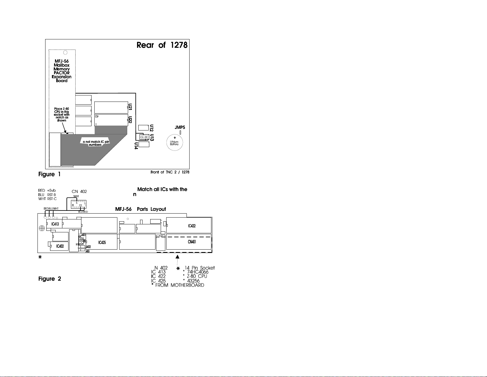
Expansion Board Installation ............................................................................2
RAM Expansion................................................................................................7
Firmware EPROM Upgrade..............................................................................7
MFJ Pactor........................................................................................................8
Online modes ......................................................................................8
FEC/ UNPROTO..................................................................8
Monitoring............................................................................8
Speedup/Speeddown.............................................................9
Automatic online compression..............................................9
Flow Control.........................................................................10
AMTOR while in PACTOR mode......................................................10
Changeover - Type ahead .....................................................10
Digital Memory ARQ..........................................................................11
LEDs...................................................................................................11
CW Identifier ......................................................................................12
MFJ PACTOR Commands................................................................................13
Firmware Upgrade.............................................................................................18
Upgrade without Grey-Level modem................................................................18
Upgrade with the Grey-Level modem ...............................................................20
Multi-Level Operation without Using Special Terminal Program ......20
Multi-Level Operation with Special Terminal Program......................20
Special Terminal Programs...................................................20
Terminal Parameters Changes...........................................................................21
Optional Items Available for your MFJ-1278 ...................................................22
Firmware Installation.........................................................................................23
Documantation Upgrade....................................................................................23
Firmware Release 4.1 Documentaion................................................................24
Automatic Signal Analasis (ASA).......................................................24
ASA Operation .....................................................................24
MARS Operation ................................................................................27
Mars Operation.....................................................................27
Operation Hints for Multicom...............................................28
The MARsmode Command ..................................................29
SSTV Operation Update .....................................................................29
FAX Operation Update .....................................................................................31
Host Mode ............................................................................31
MODEM Calibration Procedure Update...........................................................32
Calset Values Update............................................................35

MFJ-56A/B/C Mailbox Memory / Pactor Expansion
ii
PACKET Mailbox Update ................................................................................35
Set Up your Easy-Mail Mailbox .........................................................36
Mailbox Operation ............................................................................................43
Additional Mailbox Features...............................................................47
Forwarding............................................................................47
Eliciting Reverse Forwards...................................................48
Remote Heard Log................................................................49
Chat Mode ............................................................................49
Page SYSOP.........................................................................49
Remote SYSOP.....................................................................50
Mailbox CText......................................................................50
Idle Timeout..........................................................................50
Abort.....................................................................................50
Mailbox Commands Update................................................................51
Additional Commands Update ..........................................................................57
Command Default Update.................................................................................62

MFJ-56A/B/C Mailbox Memory / Pactor Expansion
0

MFJ-56A/B/C Mailbox Memory / Pactor Expansion
1
MFJ-56 A/B/C
Thank You for purchasing the MFJ-56A/B/C mailbox memory/Pactor
expansion board for your MFJ multimode. The MFJ-56 is for MFJ-1278 and
MFJ-1278T. The MFJ-56 memory/Pactor expansion board is supplied with
the most recent EPROM firmware upgrade. Documentation for the firmware
is also supplied.
You will notice that some sockets on the memory expansion are not
populated (U413, U422 & U425) when received. These sockets will be
populated with ICs to be transfered from the motherboard.
The various memory expansion boards for the MFJ-1278/T are as follows:
Model No. SRAM Size
MFJ-56A 32K
MFJ-56B 128K
MFJ-56C 512K
Note that the above models use the same memory expansion board but are
packed with a different RAM IC.
The extra memory provided by the expansion boards are dedicated solely for
the use of the packet mailbox. The firmware of the multimode does not
allocate this additional memory to other operations. Battery back up for the
memory board is supplied from the mother board.
EXPANSION BOARD INSTALLATION
In this installation you will be required to remove three ICs from the mother
board and transfer them to the expansion board. Please handle these ICs
carefully and make note of the IC numbers and their orientation.
Throughout this installation instruction we will use "TNC" to refer to the
MFJ-1278 and MFJ-1278T multimodes.

MFJ-56A/B/C Mailbox Memory / Pactor Expansion
2
Please perform the following procedure very carefully:
1. Disconnect all cables from the TNC, including power, radio and
computer.
2. Remove the top cover of the TNC by removing the four (4) screws on
the sides the unit. Then lift the cover off.
3. Remove the jumper off of JMP5. This takes the lithium battery out of the
circuit. If your TNC has a MFJ-2400 modem installed, remove it. Set it
aside, it will be re-installed later.
NOTE: When removing ICs from your TNC, ensure that you do not bend
or break any of the pins.
4. Using a small flat tip screwdriver remove the following ICs from your
TNC:
U13--74HC4066 U25--NEC 43256-10L or Equiv.
U22--Z0840004PSC Z80 CPU U23--SYSTEM EPROM
5. Install the ICs which were removed from your TNC in the above step.
Take note as to the orientation of the IC. Match up the NOTCH on the
IC to the NOTCH on the IC socket on the expansion board. Refer to
Figure 2 parts layout diagram for proper installation of the ICs.
Install the ICs removed from the mother board to the memory board as
follows:
74HC4066 (U13) in socket IC-413
43256 (U25) in socket IC-425
Z80 CPU (U22) in socket IC-422
A new EPROM with the new firmware is already installed on the
expansion board. There will be no EPROM installed on the TNC
motherboard.
NOTE: The old EPROM removed from the mother board will not be used.

MFJ-56A/B/C Mailbox Memory / Pactor Expansion
3

MFJ-56A/B/C Mailbox Memory / Pactor Expansion
4
NOTE: When installing ICs onto the memory board, ensure that you do
not bend or break any pins. Ensure all pins are in the IC socket.
6. Check and make sure that there no IC pins are bent under the IC itself.
Check and make sure that no IC pins are broken off. Do this before
proceeding beyond this point.
7. Set the expansion board aside for now.
8. Please refer to Figure 1 when performing this step. Using a small
phillips screwdriver remove the PC hold-down screw in the left rear
corner of the TNC mother board, this is refered to as HOLE "A". Do
not let this screw out of your sight, you'll be using it here shortly.
9. Take the 1/2" hex spacer supplied and install it in HOLE A, as noted in
Figure 1 in this instruction. This is the same place where you removed
the screw in Step #8. This is an aluminum spacer DO NOT OVER
TIGHTEN it, you will STRIP the THREADS.
10. Now with the memory board in one hand, plug the free end of the 40-pin
ribbon cable into the IC socket labeled U22 (please refer to Figure 1;
this is the same one which you removed the Z80 CPU from earlier in this
procedure) on the mother board. Be sure to orient the blue connector so
that pin 40 and 1 on the blue connector are oriented to the right side of
the IC socket, (with the front panel of the TNC facing toward you). You
will need to twist the cable slightly. Ensure that you leave the CN402
pigtail free and clear, do not let it become pinched or caught up
underneath anything.
NOTE: If you do not have an MFJ-2400 board installed in the TNC, skip
to step 14.
11. If you have an MFJ-2400 modem installed position the 40-pin cable, so
the cable is not going to be pinched by the mounting stud for the MFJ-
2400 modem.
12. Now you can re-install your MFJ-2400 modem. Be sure that you do not
pinch any of the wires of the 40-pin ribbon cable or the CN402 pigtail
when you tighten the MFJ-2400 down. This will cause problems with
both the MFJ-2400 and the memory board.

MFJ-56A/B/C Mailbox Memory / Pactor Expansion
5
13. Find the original hold-down screw which you removed from the TNC
motherboard earlier. Secure the expansion board to the 1/2" spacer
which you installed earlier. Again this an aluminum spacer, DO NOT
OVER-TIGHTEN it! You will STRIP the THREADS.
14. Take note of the location of the NOTCH on CN402. Now plug CN402
into the IC socket labeled U13 (socket which the 74HC4066 was
removed earlier) on the TNC mother board. Please refer to either Figure
1. Plug it in so the NOTCH is pointing toward the lithium battery.
Make sure it is firmly in place!
15. Remove the paint (if any) from around the mounting holes on the outside
of the chassis and the inside of the cover. This can be done with either
light sandpaper or a knife blade. This will eliminate any EMI from the
TNC caused by the additional large ribbon cable. This concludes the
installation of the mailbox memory expansion board. However, before
you start putting things back to together double check everything you
have already done.
Final Inspection
Before closing up the TNC do a final inspection. Please check all of the
following:
1. Check all connections to ensure that they are all secure.
2. Make sure that there are no pins bent or broken on any of the IC's or
connectors installed in this procedure.
3. Make sure that there are no wires pinched or caught up under any of the
screws, circuit boards or connectors.
4. Lastly, give your TNC one last look over for any debris or foreign matter
on the main PC.
If all of the above checks out then you can re-install the battery jumper
JMP5. Connect the computer cable to the TNC, apply power and see if you
can obtain the TNC's sign-on message. If not go back and double check the
entire installation procedure. If the TNC signed on properly, install the
cover. Reconnect your TNC or multimode to your radio and computer.
Follow the instructions given by the rest of this documentation to operate
your mail box.

MFJ-56A/B/C Mailbox Memory / Pactor Expansion
6
RAM EXPANSION
The RAM on the 32K board can be increased to 128K or to 512K. For the
128K board you can increase the RAM to 512K. This can be done simply by
replacing IC424 on the memory board and relocate the jumper at J401
header. Refer to Figure 2 and the following chart. RAM chips can be
ordered from MFJ Enterprises, Inc.
ITEM No. RAM TYPE J401 POSITION
MFJ-45A 43256LP-10 (32K) The (2) inside most pins
MFJ-45B 431000LP-10 (128K) The (2) middle pins
MFJ-45C 8512LP-10 (512K) The (2) outside most pins
FIRMWARE EPROM UPGRADE
There are two versions of firmware EPROM upgrade for both the MFJ-1278
and MFJ-1278T Multimodes. One version, the MFJ-48, supports standard
TNCs without the RAM Expansion Board. The other version, the MFJ-48B,
supports the MFJ-1278/T with a memory expansion board and MFJ-
1278B/BTs. Since you have already installed the RAM Expansion Board,
remember to request the MFJ-48B version when ordering EPROM upgrades
for you TNC in the future.

MFJ-56A/B/C Mailbox Memory / Pactor Expansion
7
MFJ PACTOR
This section of this instruction pertains strictly to the PACTOR upgrade
feature. It will explain the functions and then go through the PACTOR
commands.
Online modes
As in packet, pactor also contains command and converse modes. Please
note that switching between them is modelled on the "NEWMODE ON"
procedures in packet. To manually switch between modes, ^C (the default
CMDCHR) or a 'Break' signal takes you to cmd mode, and the letter "K"
(**not CONVerse**) takes you to converse mode.
Once connected, the link acts much like AMTOR. The station originating
the connection is deemed to be the master and he remains in transmit mode
until he or the slave initiates a changeover. Either station may reverse the
direction of the link by issuing a control-Y changeover (^Y) in converse
mode.
FEC/ UNPROTO
Unproto: "FEC/UNPROTO" packets are transmitted UREPEATS+1 times.
Selecting larger values of UREPEATS reduced throughput but enhances
reliability. To transmit in UNPROTO mode, issue the appropriate unproto
command and type away. When done, break out to "p_cmd:" mode and type
'D' to terminate transmission.
MONITORING
Monitoring unproto: Unlike the German pactor controller, our controller is
always in listen mode (if MONITOR is ON) except when connected and in
one other situation. This other situation occurs when
a) we've just terminated a 2-way pactor contact and
b) the other side initiated the disconnect.
To prevent Uncontrolled Disconnects <the capitalized term is defined in the
ptc docs>, we are unable to listen to all kinds (unproto, connected, and
connect request) of third party pactor transmissions for ( WAIT x
Cycle_Time ) seconds after receiving the other side's last disconnect. {Cycle
time is 1.25 or 1.4 seconds}

MFJ-56A/B/C Mailbox Memory / Pactor Expansion
8
[Connect] message: Other station's connect attempts received when idle are
monitored with a message containing the called station's callsign. To
sucessfully monitor a connect attempt to someone else, the called callsign
must be at least 4 characters in length, and the signal of sufficient quality that
the 200 baud area is received error-free. Unfortunately, the callsign in the
connect-attempt packet (unlike all other other monitored data) is subject to
corruption; the Pactor protocol did not provide for error-free connect
packets. Therefore, you may at times see a garbled callsign in a [Connect]
message, but it should be rare. Remember, this "garbling" affects only
monitored connect-attempt packets. It does NOT affect ARQ or FEC data
packets because they are error-protected by a sophisticated CRC checking
scheme.
Speedup/Speeddown
Speedup and speeddown: When the TNC is the receiving station (IRS),
after MAXDOWN consecutive failures to receive a 200 baud packet the
TNC requests a speedown to 100 baud. Speedup occurs when MAXUP
consecutive error-free 100 baud packets are received provided speedup is not
inhibited by NO200 set to ON.
Bad band conditions: Faster links may sometimes be achieved during
unusually poor conditions by avoiding 200 baud operations. Setting NO200
to ON instructs the TNC to avoid 200 baud operation in a compatible way.
When forced 100 baud operation is combined with digital memory ARQ
(always on by default), the TNC is capable of operation during extremely
poor (fading, distortion, QRN) conditions such as are found on 160, 80 and
40 meters.
Automatic online compression
Huffman coding: Huffman coding offers somewhere between 2:1 and 4:1
compression on lower case German and English plain text. In receiving
modes, conversion to 8 bit data is automatic. On transmit, the TNC
packetizes outgoing data and transparently selects the mode. Huffman
coding will be used if all data are 7 bit ASCII characters, and huffman coding
is at least as efficient as straight 8-bit coding.

MFJ-56A/B/C Mailbox Memory / Pactor Expansion
9
Flow Control
Flow control: Hardware flow control is always on. Software flow controls
defaults to on using the XON and XOFF parameters. Unlike TNC
operations, the same characters are used for receive flow control as for
transmit flow control. Typein flow control is only effective while entering
commands at the "p_cmd:" prompt.
AMTOR while in PACTOR mode
AMTOR calls (1278 rev 10 only): MFJ's Pactor implementation is
downward compatible with AMTOR-only stations. That is, even if the TNC
is in pactor "p_cmd:" mode it will automatically detect and respond to
incoming AMTOR ARQ connection attempts. This allows your buddies with
AMTOR-only controllers to call you even though you are in the pactor mode.
To enable the AMTOR call detection feature, you must have previously
entered your AMTOR selective callsign in the "a_cmd:" MYSELCAL
parameter. Furthermore, you must have the appropriate sideband (usually,
LSB) selected because unlike PACTOR, AMTOR is polarity-dependant.
How AMTOR-while-in-PACTOR mode detection works: Pactor
continuously monitors the channel for pactor packets and for AMTOR call
packets that match your AMTOR SELCALL. When PACTOR hears your
AMTOR SELCALL, the TNC enters the "a_cmd:" AMTOR mode in an
attempt to complete the link. If the link is not established within 30 seconds
of entry to AMTOR then the TNC automatically returns to PACTOR mode.
If the link is established, the TNC remains in AMTOR mode for the duration
of the connection and for an additional 30 seconds after the link terminates.
Upon expiration of the 30 seconds, the return to PACTOR is accomplished
automatically.
Changeover - Type ahead
One of the many ways PACTOR resembles AMTOR is the protocol's one
way nature. Data are transmitted in one direction at a time. The calling TNC
is, initially, the Information Sending Station (ISS), i.e. the sender. The other
station is, initially, the Information Receiving Station (IRS). To reverse data
direction, either the sender or the receiver must send the changeover
character (default: ^Y -- changeable).
The changeover character has an affect dependant upon the current state
(sending or receiving) of the TNC. If the TNC is currently the ISS, the

MFJ-56A/B/C Mailbox Memory / Pactor Expansion
10
changeover takes effect when all pending characters are acknowledged by the
remote. When the TNC is the IRS, the changeover takes effect immediately
and any characters typed prior to the changeover are queued for immediate
transmission (type-ahead).
Digital Memory ARQ
MFJ's pactor incorporates Digital memory ARQ. Memory ARQ enables the
reconstruction of a good packet when a retried packet is repetively received
with one or more bit errors. Memory ARQ is accomplished by accumulating
the bit value (1 or 0) derived from the RF input port during sucessive
receptions of the same error-laden packet, and then passing the series of
accumulations to the receiver shift register. Thus a correct packet may be
reconstructed from 2 or more "bad" packets.
The number of accumulations performed for each bit are controlled by the
MAXSUM parameter. Larger values tend to increase the effectiveness of the
memory ARQ scheme, but only up to a point. A too large value, in the
presence of excessive QRM, QRN, or QSB, tends to accumulate so many bit
errors that the subsequent reception of an almost perfect packet will be
inadequate to overcome the accumulated noise. On the other hand, a too
small value will accumulate too few samples to correct for moderate error
rates. The default value represents a compromise; feel free to play around
with the setting.
LEDs
The STA and CON leds on the front of the TNC will help in determining the
TNC status while in the PACTOR mode. Please refer to Table 2-1 on the
following page for information on what is happening during the four (4) led
conditions:

MFJ-56A/B/C Mailbox Memory / Pactor Expansion
11
STA CON ACTION
0 0 MON: The TNC is idling and has not monitored
any information packets in the past second
RX: n/a
TX: n/a
0 1 RX: Sending ack control sig
TX: Last packet acknowledged
MON: Received new packet
1 0 RX: Dupe rcvd; sending Request control sig
TX: Received request control
MON: Received dupe packet
1 1 RX: Info packet missing; sending request
TX: Control sign missing; retransmitting
MON: n/a
Table 2-1
Led Conditions in PACTOR
CW Identifier
Should CW identification be required, the 1278 supports 8 cw identification
modes. Seven automatic modes are selected by the bit-mapped WIDMODE
parameter. Bit positions within CWID MODE enable timed cw id, cwid n
incoming events, cwid on outgoing events, and any combination of the three
for a total of 7 modes.
The timed mode requires some explanation. The counter controlling the
transmission of the timed CWID must be initially started at the beginning of
each link with either the manual "ID" command or one of the initial
CWIDMODE features selected by CWIDMODE bits 1 or 2. A fully
automatic CW ID is achieved by setting CWIDMODE to 3. Reduced levels
of automation are selected by other combinations.
The eighth mode is manual cwid. Invoke manual CWID by issuing the "ID"
command.

MFJ-56A/B/C Mailbox Memory / Pactor Expansion
12
MFJ PACTOR COMMANDS
Generally, the following commands are only valid when issued at the p_cmd
prompt. Note that a few of the parameters use the same names as packet
commands but the parameters themselves are NOT shared between the
different modes.
Connect [call]-Attempts to connect with [call] using regular timing
AUtolf ON/OFF-default ON - Works same as packet
CBell ON/OFF- default OFF- Same as packet
CHObell ON/OFF-default ON- When ON, an ASCII bell (0x07) character
is sent when the pactor link changes directions.
CHOChar nnn- 0 <=nn<=255, default 25 (^Y) - 0 disables - This is the
character the TNC initiates a pactor changeover action
with. See above.
CMDCHR nnn-0<=nn<=255, default 3 (^C)- Same as COMMAND in
1278
CWidmode nn- 0<=nn<=255, default 0--This bitmapped parameter
selects various pactor CW ID features.
Bit 1 Selects Bit 0 Selects
1 selects 1 enables
initial idtimer for
cwid on cw id on
locally Remotely automatic timed
initiated cw ident
calls and calls and
disconnects disconnects
(outgoing) (incoming)
Also see IDTIME
DISPLAY- Immediate command; displays all displayable
parameters.
Disconne-Cleanly terminates the current ARQ or FEC connection.

MFJ-56A/B/C Mailbox Memory / Pactor Expansion
13
DDisc-"Dirty" immediate termination of current connection.
EAa ON/OFF- default ON - "Echo as ACKd". When ON the TNC
echos transmitted data to the terminal upon receipt of
the remote's acknowledgement of the same data.
ECho ON/OFF- default ON - Same as 1278, except that echoing is
deferred when EAA is ON as described above.
ERrstrin cccc- default '[...]' - ccc is 1-5 chars long. Selects the string
to display when an unconnected packet is monitored out
of sequence. Set first character to '%' or '&' to clear.
EXactcal ON/OFF- default ON - When ON, the TNC responds to connect
packets that match all the letters in your callsign and no
more. When OFF, the looser "buggy" pactor
specification comes into play and your TNC responds
to any connect packet containing at a minimum the
contents of MYCALL. EXACTCAL matching will not
always work to filter out improper callsigns when the
offending unit is the pacomm pactor version 1.0 unit
because of its use of regular ascii 0x55 ("U") characters
to fill and terminate callsigns. MFJ uses ascii 0x0f as
specified in pactor documents, instead of 0x55 to fill,
and thus fixes the bug.
FLow ON/OFF- default ON - same as 1278 but operates only in p_cmd
mode. This limitation is due to rapidly changing
transmit<>receive status of a pactor link. Applying
FLOW to data would improperly hold off the important
changeover signal and is therefore disallowed.
ID- Immediate command - Generates an immediate CW ID
IDTime nn- 6<=nn<=255, default 59 (590 seconds) - This
parameter specifies the time interval/10 between
automatically generated cw id events. The actual time
yielded equals IDTIME * 10 seconds. IDTIME is only
relevant when bit 0 of the CWIDMODE parameter is
set to 1.

MFJ-56A/B/C Mailbox Memory / Pactor Expansion
14
KPuts you in converse mode
LC [callsign]- Initiates an ARQ link to callsign using extended
(longpath) timing to support long txdelays or long skip
paths
LEdmode 0/1 - default: 1 - Controls whether the 1278 flashesit's LEDs
rapidly for each cycle a 200 baud packet is
sent,received, or expected. The user may find the
flashing of benefitin evaluating link quality, and as an
indication that the high-throughput 200 baud mode is
active. Also see "NO200" parameter.
LFADD ON/OFF-default OFF - same as 1278
MAXDown nnn-2<=nnn<=48, default 4 - Controls the number of 200
baud information-packet receive errors the TNC
tolerates prior to requested speed down to 100 baud.
MAXSum nnn- 5<=nnn<=120, default 30 - Specifies the number of
cycles of error-laden information packets received that
are accumulated in the digital memory arq sum buffer
for reconstruction. When MAXSUM consecutive
information receive errors occur, on the next receive
cycle the sum buffers are re-initialized to inhibit the
corruption of real-time reception by historical receive
errors.
MAXUp nnn-2<=nnn<=48, default 10 - MAXUP specifies how many
consecutive good receptions of 100 baud information
packets are required prior to the TNC's requesting a
speeding-up to 200 baud. Note that a NO200 ON
setting preempts the value in MAXUP, and if on, the
TNC will never request a speedup regardless of the
MAXUP setting.The MAXUP value should be small
enough to enable timely speed up in relatively good
conditions while being large enough to avoid pointless
speedups during bad conditions.

MFJ-56A/B/C Mailbox Memory / Pactor Expansion
15
Monitor ON/OFF-default ON - same as a 1278 with MCON off. I.e.,
When not connected and MONITOR is ON, the TNC
displays monitored data and connect attempts.
MYcall [callsign]-Your callsign, up to 8 chars (default: MFJPACTR)
MYSelcall [4 char amtor selcall]- default MFJJ - This is used temporarily
to debug the amtor call detection. When integrated
with the 1278 this command will go away and
PACTOR will find the selcall in ZAMTOR's memory.
In standalone pactor, a message "[AMTOR call
received]" is displayed.
NO200 ON/OFF-default OFF. Controls whether 200 baud links are to be
discouraged. The TNC accomplishes this in two ways:
(1) Speedups are inhibited, and (2) Incoming connect
requests are acknowledged for 100 baud. NO200
works most effectively when both units are capable of
NO200 operation. Regardless of the setting of NO200,
the TNC complies. This ensures connectivity with non-
MFJ units.
PASS nnn-0<=nn<=255 default ^V - Same as 1278. (Doesnt work
for ^Y Changeover)
PTOver-> see CHOCHAR command
PTSend-> see U1 command
REtries nn-(0<=nn<=255) The number of error cycles tolerated
before unilaterally terminating the link. (Also see
WAITDISC)
STatus-Displays debug information. See appendix.
TRace ON/OFF-Continuous debug info display
TXdelay nn-25 <= nn <= 2default: 2 (20ms) Similar to AMTOR's
DELAY and packet's TXDELAY. The actual delay
yielded is (TXDELAY * 10 ms ) ). NB If the combined
TXDELAYs of both stations involved in the link
exceeds about 180ms, then shortpath connections may

MFJ-56A/B/C Mailbox Memory / Pactor Expansion
16
not work, particularly at longer distances. If difficulty
is experienced, try using the longcall command to
connect ("LC").
U1-Initiate 100 baud FEC.
U2-Initiate 200 baud FEC.
URepeats nn-1<=nn<=7, default 1. The UREPEATS parameter
specifies how many retransmissions to perform for each
FEC data packet sent. Ex: UREPEATS 1 causes each
FEC packet to be sent two times.
WAitdisc nn-(10<=nn<=255) default: 20 The number of cycles our
TNC waits to reply to the other TNC, that having
requested a disconnect, fails to hear our disconnect
acknowledgement.
XOFF nn-0 <= nn <= 255 default: ^S Same as 1278
XON nn-0 <= nn <= 255 default: ^Q Same as 1278
*see discussion above for more on XON/XOFF software flow control

MFJ-56A/B/C Mailbox Memory / Pactor Expansion
17
FIRMWARE UPGRADE
The MFJ-48B is the latest firmware upgrade for the MFJ-1278 and the MFJ-
1278T multi-mode data controller. This firmware is Release 4.1. Any MFJ-
1278 or MFJ-1278T with the mailbox memory/PACTOR expansion board
installed must use firmware Release 4.1 which is supplied with the memory
board.
Firmware Release 4.1 features as follows:
1. Supports 16 gray level FAX and SSTV.
2. Supports transmit and receive color SSTV in real time.
3. Supports PACTOR operation. Includes Digital Memory ARQ, Auto-
matic On-Line Compression and a CW Identifier.
4. Supports packet mailbox memory expansion to 32K, 128K or 512K.
5. Enhanced mailbox that allows separate callsign for the mailbox.
Mailbox now stays ON during packet connects.
6. Other mailbox features are: Auto and manual mail forwarding, auto and
manual reverse mail forwarding, remote sysop access, sysop paging,
chat mode, mailbox Ctext and much more mailbox features.
7. Dedicated Mars mode.
8. Improved Automatic Signal Analysis (ASA).
9. Host mode.
10. An echo-as-sent command is installed to allow echoing of each
character to the screen as its being transmit in CW, RTTY and ASCII.
This firmware can be installed in an MFJ-1278/1278T with the MFJ-
56A/B/C expansion board installed, or an MFJ-1278B/BT. The firmware
can also be installed in the same units with or without the multi-gray level
FAX/SSTV modem installed.
It is very important that you read this instruction booklet concerning
Release 4.1 before you install the firmware.
UPGRADE WITHOUT MULTI-GRAY LEVEL MODEM
If you have purchased the MFJ-48B and installed it in an MFJ-
1278/56A/B/C combination which does not have a multi-gray level modem,
you should be aware that the features and commands related to the use of the
multi-gray level modem will not apply to you. The MFJ-1278 multi-gray
level modem board mounts vertically on the right side and it is connected to
the mother board by a 20-line ribbon cable.
This manual suits for next models
7
Table of contents