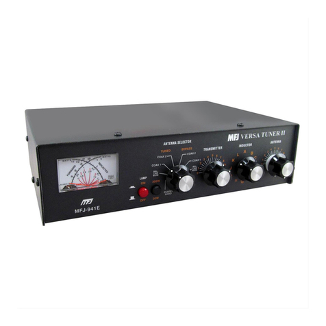
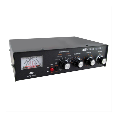
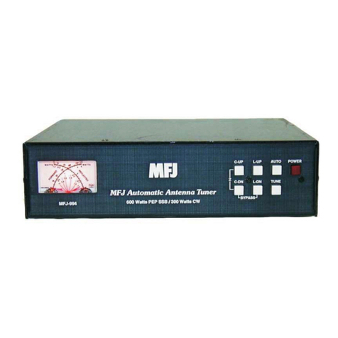
MFJ VERSA TUNER II MFJ-941D User manual

www.SteamPoweredRadio.Com
MFJ-941D
VERSA
TUNER
II
INSTRUCTIONS
Thank
you
for
purchasing
the
MFJ-941D
VERSA
TUNER
II.
The
MFJ-941D
is
designed
to
match
vees,
verticals,
mobile
whips,
beams,
random
wires,
and
others
fed
by
coax
lines,
balanced
lines
,
or
a
single
wire.
A
1:4
balun
is
built
in
for
connection
to
balanced
lines.
This
unit
will
handle
up
to
300
watts
of
RF
output
power
from
the
transmitter
from
160
through
10
meters.
The
MFJ-941D
will
monitor
either
SWR
or
RF
transmitter
power
in
two
ranges,
30W
or
300W .
The
antenna
selector
switch
allows
switching
to
one
of
the
two
coax
fed
antennas
(direct
or
through
tuner)
and
either
a
balanced
line
antenna
or
random
wire
antenna.
A
bypass
position
allows
switching
to
a dummy
load
or
a
direct
coax
antenna
.
The
tuner
is
bypassed
but
not
the
meter
ciruit
when
the
ANTENNA
SELECTOR
switch
is
switched
to
BYPASS, DIRECT
COAX
1,
or
DIRECT
COAX
2
positions.
CAUTION:
Do
not
use
the
MFJ-941D
for
over
300
watts
of
RF
output
power,
even
in
the
bypass
or
direct
positions.
Do
not
operate
the
antenna
selector
while
transmitting.
INSTALLATION
1.
Install
the
MFJ-941D
between
the
transmitter
and
the
antennas.
A
coax
line
is
connected
between
the
transmitter
and
the
S0-239
coax
connector
marked
TRANSMITTER
on
the
tuner.
2.
One
or
two
coax
fed
antennas
may
be
connected
to
the
S0-239
coax
connectors
marked
COAX
1
and
COAX
2.
NOTE:
Coax
1
and
coax
2
antennas
can
be
connected
directly
to
the
transmitter
by
turning
the
antenna
selector
to
COAX
1 DIRECT
or
COAX
2 DIRECT .
3.
A
random
wire
antenna
may
be
connected
to
the
five-way
binding
post
marked
WIRE.
The
random
wire
antenna
should
be
long,
high,
and
as
clear
of
surrounding
objects
as
possible.
Do
not
ground
the
random
wire
antenna
but
make
sure
that
the
tuner
is
well
grounded
to
the
transmitter.
A
five-way
binding
post,
marked
GND,
is
provided
for
the
ground
connection.
4.
A
balanced
line
fed
antenna
may
be
connected
to
the
two
five-way
binding
posts
marked
BALANCED
LINE,
along
with
a
jumper
wire
from
the
WIRE
binding
post
to
the
adjacent
BALANCED
LINE
binding
post,
as
indicated
by
a
dotted
line
on
the
HFJ-941D.
This
couples
the
MFJ-941D
to
the
balanced
line
through
a
1:4
balun
.
NOTE:
Either
a
balanced
line
or
random
wire
antenna
can
be
connected
at
one
time.
If
a
random
wire
antenna
is
used,
make
sure
that
there
is
not
a
jumper
wire
between
WIRE
and
BALANCED
LINE.
5.
An
antenna
or
dummy
load
may
be
connected
to
the
S0-239
coax
connector
marked
BYPASS
COAX.
The
antenna
switch
on
the
BYPASS
position
will
bypass
the
tuner
and
allow
the
MFJ-941D
to
be
used
as
an
SWR
meter
or
a
wattmeter
.
PA
GE
1

www.SteamPoweredRadio.Com
THE
SWR/WATTHETER
The
SWR/WATTMETER
of
the
MFJ-941D
can
be
used
with
the
tuner
or
by
itself
.
The
SWR/WATTHETTER
is
between
the
transmitter
and
the
tuner
when
the
antenna
switch
is
in
the
COAX
1,
COAX
2,
or
WIRE/BAL
positions.
The
SWR
meter
is
sensitive
down
to
approximately
5
watts
RF
output
.
The
SWR
reading
will
not
be
accurate
for
a
transmitter
power
of
less
than
5
watts
.
FORWARD
AND
REFLECTED
POWER
1.
Set
the
POWER/SWR
switch
to
POWER.
2.
Set
the
300/30
watt
switch
for
the
desired
range
.
3.
Set
the
FWD/REF
switch
in
for
forward,
out
for
reflected
power
.
4.
Transmit
a
steady
carrier
and
read
the
power.
SWR
MEASUREMENT
1.
Set
the
POWER/SWR
switch
out.
2.
Set
the
FWD/REF
switch
in.
NOTE
:
It
does
not
matter
which
position
the
3JJ/3J
watt
switch
is
in
for
measuring
SWR.
3.
Transmit
and
adjust
the
SWR
SENSITIVITY
control
for
fu
l l
scale
reading.
4.
Set
the
FWD/REF
switch
out
and
read
the
SWR.
OPERATION
OF
THE
TUNING
SECTION
The
INDUCTANCE
switch
on
the
HFJ-94
1D
presents
a
minimum
of
inductace
at
position
"A"
and
a maximum
of
inductance
at
position
"
L".
Less
inductance
is
needed
at
high
frequencies
for
the
same
impedance.
The
TRANSMITTER
and
ANTENNA
controls
both
present
a maximum
of
capacitance
at
position
1.
For
optimum
operation
of
the
MFJ-941D,
the
transmitter
must
be
tuned
for
a
5J
ohm
output
impedance
for
the
frequency
band
in
operation
. The
transmitter
can
be
tuned
with
the
MFJ-941D
connected
by
connecting
the
50
ohm
load
to
the
BYPASS
COAX
connector
and
turning
the
antenna
switch
to
the
BYPASS
position.
The
HFJ-941D
is
then
used
only
as
an
SWR
meter
or
a
wattmeter
.
NOTE:
Always
tune
the
transmitter
at
a
lo
w
outEut
power.
After
properly
tuning
the
transmitter,
turn
the
antenna
switch
to
the
desired
antenna
and
tune
the
tuner
for
minimum
SWR
as
described
below
.
Do
not
readjust
tht
transmitter
setting
after
loading
it
to
the
50
ohm
load.
1.
Set
the
TRANSMITTER
and
ANTENNA
controls
to
3.5.
are
half
opened).
(The
capacitors
2.
Rotate
the
INDUCTANCE
control
until
maximum
noise
is
obtained
in
the
receiving
mode.
3.
Set
the
POWER/SWR
switch
to
SWR
and
the
FWD/REF sw
itch
to
FWD.
It
does
not
matter
which
position
the
3JJ/3J
watt
switch
is
in
PAGE
2

www.SteamPoweredRadio.Com
for
measuring
SWR.
Set
the
transmitter
to
the
tune
position
and
transmit.
4.
Turn
the
SWR
SENSITIVITY
control
clockwise
unt
i l a
full-scale
deflection
is
obtained.
If
a
full-scale
deflection
cannot
be
obtained,
increase
the
output
power
from
the
transmitter.
5.
Set
the
FWD/REF
switch
to
the
REF
for
the
SWR
reading.
6.
If
the
SWR
is
not
1: 1,
then
tune
the
MFJ
-941D
for
a
minimum
SWR
.
7 .
While
transmitting
,
and
with
the
I N
DUCTANCE
control
set
the
same
as
for
Step
2 ,
alternately
adjust
the
TRANSMITTER
and
ANTENNA
controls
for
a
minimum
SWR
.
Sice
the
TRANSMITTER
and
ANTENNA
control,
interact,
the
two
controls
can
best
be
adjusted
b y
turning
the
.TRANSMITTER
control
at
a
small
increment
at
a
time
and
t
hen
rotating
the
ANTENNA
control
for
the
minimum
SWR
.
Repeat
this
until
a
minimum
SWR
is
obtained
.
8.
If
a
SWR
reading
of
1: 1
is
not
achieved
,
increase
or
decrease
the
INDUCTANCE
control
one
position
and
repeat
STEP
7.
N
OTE
:
If
a
SWR
cannot
be
achieved
at
this
point,
repeat
Step
7
for
each
INDUCATNCE
contro
l
position
.
Again,
do
this
in
the
tune
mode
or
at
a
low
transmitting
power.
9.
After
a
minimum
SWR
is
achieved,
readjust
the
SWR
sensitivity
(to
get
a
more
accurate
reading
of
the
SWR)
by
pushing
the
FWD/R
EF
switch
in
to
FWD
and
adjust
the
SWR
SENSITIVITY
control
for
a
full
scale
meter
deflection.
Switch
the
FWD/REF
switch
to
the
REF
position
for
the
SWR
reading
.
The
transmitted
power
may now
be
sw
itched
to
3JJ
watts.
The
SWR
sensitivity
must
be
re,et
again
after
full
power
is
applied
.
The
ANTENNA
and
TRANSMITTER
controls
may
need
fine
adjustment
if
the
SWR
is
not
1:1
at
hig~
pow~r .
NOTE:
On
the
16J
meter
band
,
excessive
heatin~
or
arching
may
occur
.
Reduce
the
transmitter
output
power
u~
til
it
stops
.
1J.
To
read
the
transmitt
~
po
w
er
,
pus
r
the
POWER/SWP
switch
i ~
to
POWER
and
the
3JJ/3J
watt
switch
to
~
~ichever
powe
scale
you
~ant.
To
read
reflected
power,
put
the
FWD/REF
switch
in
the
REF
position.
11
. A
SWR
of
1:1
can
occur
from
more
than
one
set
of
control
settings
on
the
MFJ-941D
. When a
SWR
of
1: 1
is
obtained
,
be
sure
to
chec
k
transmitter
power
and
make
sure
that
the
transmitter
power
is
relatively
high
.
If
the
transmitter
power
has
decreased
substantially
,
try
another
INDUCTANCE
control
setting
and
repeat
Step
7 .
'
12.
When
using
the
NFJ-941D
for
receiving
only
,
tune
the
MFJ
-941D
as
described
in
Step
1
and
Step
2.
PAGE
3

www.SteamPoweredRadio.Com
ADDITIONAL
NOTES
AND
CA
UTI
ONS
1,
Do
no
t
use
the
MFJ-941D
for
over
300
watts
of
RF
o
utput
po
we
r .
even
in
the
BYPASS
or
the
DIRECT
COAX
p
osi
tions
.
2.
Do
not
op
erate
the
antenna
switch
wh
ile
transmitting.
3.
For
recalibrating
the
power
scale
settings.
use
the
trim
pots
just
behind
the
meter
. Loo
king
f
ro
m
the
f
ront
.
the
left
trimpot
adjusts
the
300
w
at
t
sca
le
and
the
right
adjusts
the
30
watt
scale
.
r------
-
I
I
LI
_-+-...,,.,......,,1\-
x_
MI
T
>---+-+----.---f.!=!.\\-----
.......
_,,,,..,,
TRANS
MITTE
R
TOROID
-----
----
1
BYPASS
COAX
208
pP
208
pF
Slb
8.2K
JOO
100K
I,
OluF
500
K
RL
S2
INDUCTIVE
MATCHIN
G
,OluF
.OluF
.I
MPJ-9410
SCHEMATIC
DIAGRAM
PAGE
4
•
•
WIRE
I
JUMPER
*
I
t------1,1
GROUND
•
use
juJDper w
ith
BALANCED
LINE
I

www.SteamPoweredRadio.Com
I
MFJ Enterprises,
Inc
. warrants
to
the
original
owner
of
this product,
if
manufactured by
MFJ Enterprises, Inc. and purchased from an authorized dealer
or
directly from MFJ
Enterprises,
Inc
.
to
be
free
of
defects
In material and workmanship
for
a period
of
12
months from date
of
purchase provided the following tenns
of
this warranty are satisfied.
1. The purchaser must retain the dated proof-of-purchase (bill
of
sale, canceled check,
credit card
or
money order receipt,
etc
.) describing the product to
establish
the
va-
lidity
of
warranty claim and must submit the original
or
a machine-reproduction
of
such proof-of-purchase
to
MFJ Enterprises,
Inc
.
at
the time
of
warranty service.
MFJ Enterprises,
Inc
. shall have the discretion
to
deny
warranty without dated
proof-of-purchase. Any evidence
of
alteration, erasure,
or
forgery
of
proof-of-purchase
shall
be
cause
to
void any and all warranty terms immediately.
2.
MFJ
Enterprises, Inc. agrees to repair
or
replace
at
MFJ's option without charge to
the original
owner
any defective product provided the product is returned postage
prepaid
to
MFJ Enterprises, Inc. with a personal check, cashier's c
heck
or
money
order
for
$4.00
covering postage and handling.
3.
MFJ Enterprises, Inc. will supply replacement parts free
of
cha{ge for any MFJ pro-
duct under warranty upon reQuest. A dated proof-of-purchase and a
$4.00
personal
check, cashier's
check
or
money
order
must
be
provided to
cover
postage and
handling.
4 . This warranty is
NOT
void
for
owners
who
attempt to repair defective units. Techni-
cal consultation is available
by
calling
(601)
323-5869.
5.
This warranty
does
not
apply
to
kits sold
or
manufactured by MFJ Enterprises,
Inc
.
6. Wired and tested
PC
board products are covered
by
this warranty provided
only
the
wired and teated
PC
board la returned. Wired and tested
PC
boards installed in
the
owner's cabinet
or
connected to switches, jacks, cables,
etc
. sent to MFJ Enter-
prises,
Inc
. will be returned
at
the
owner's
exr,,..
-1nrepaired.
7.
under
no circumstances is MFJ Enterprises,
1,
1.
"'
for
consequential damages to
person
or
property by the
use
of
any MFJ
pro
,
t.
8. Out-of-W1rr1nty Service: MFJ Enterprises, Inc. will repair any out-of-warranty pro-
duct
provi
ded
the
unit is delivered prepaid. All charges will
be
shipped COD
to
the
owner
.
.
9.
This
warranty
Is
given in lieu
of
any other warranty
express
or
implied.
10. MFJ Enterprises, Inc. reserves
the
right
to
make changes or improvement in design
or
manufacture
without incurring any obligation
to
install
such
changes upon any
of
the
products previously manufactured.
11.
All
MFJ products
to
be
serviced
in-Wm1W1ty
or
out-of-warranty should be addressed
to
MFJ
EnterprlHa, Inc.,
t21A
Loulmtle
Road,
Starttvllle,
Mlnlulppl
39759,
USA
and must be accompanied
by
a
letter
describing the problem in detail along with a
copy
of
your
dated proof-of-purchase.
12. This warranty gives
you
specific rights, and
you
may also have other rights which
vary from state
to
state.
Table of contents
Other MFJ Tuner manuals

MFJ
MFJ MFJ-974B User manual

MFJ
MFJ Differential-T Tuner -986 User manual

MFJ
MFJ MFJ-950K3 User manual

MFJ
MFJ MatchMaker 212 User manual

MFJ
MFJ Versa Tuner II 941D User manual

MFJ
MFJ MFJ-924 User manual

MFJ
MFJ MFJ-1642 User manual

MFJ
MFJ MFJ-931 User manual

MFJ
MFJ MFJ-923 User manual

MFJ
MFJ MFJ-998 User manual
Popular Tuner manuals by other brands

Snark
Snark SN-1 instruction manual

Crestron
Crestron ATC-AUDIONET quick start guide

ADS Technologies
ADS Technologies USBAV-701 user guide

Toa
Toa WT-3800 operating instructions

Manta
Manta DVBT06SXT2 user manual

PRAGMATIC COMMUNICATIONS SYSTEMS
PRAGMATIC COMMUNICATIONS SYSTEMS TV / CATV / FM Tuner user manual