MG ANODI De Stefani ACES User manual
CGR
srl
MG ANODI
INTERNATIONAL AD
Velikotarnovsko Shosse 1
5400 Sevlievo – Bulgaria
Mobile: +39 345 8412837
Web: www. g-anodi.co
E-mail:
aces@ g-anodi.co
via V. Bottego n.41
41126 Modena - Italia
tel.- fax +39 059822673
WEB: www.cgr-aces.it
EMAIL: info@cgr-aces.it
MG ANODI INTERNATIONAL AD
Velikotarnovsko Shosse 1
5400 Sevlievo - Bulgaria
Mobile: +39 345 8412837
Web: www. g-anodi.co
E-mail: aces@ g-anodi.co

ENGLISH from page 1 to page 12 (rev. 02)
DICHIARAZIONE DI CONFORMITA’/
DECLARATION OF CONFORMITY
Fabbricante/Manufacturer:
MG ANODI INTERNATIONAL AD
Velikotarnovsko Shosse 1
5400 Sevlievo – Bulgaria
Descrizione del prodotto/
Product(s) description: Dispostivo elettronico anticorrosione per
bollitori/Electronic devices for boilers and
water-heaters corrosion prevention:
Modello (i)/Model(s): A C E S Serie H
A C E S G 2
Si certifica sotto la nostra esclusiva responsabilità che i prodotti a cui si riferisce la
presente dichiarazione sono conformi alle seguenti Direttive europee/
We hereby certify under our sole responsability, that the product(s) to which this
declaration relates is/are in conformity with the requirements of the following
European Directives:
Council Directive 89/336/EEC Directive (Electromagnetic Compatibility),
Council Directive73/23EEC Directive (Low Voltage Equipement Safety)
Council Directive 2001/95/EC Directive (General Product Safety).
E alle seguenti norme armonizzate / and with the following European Standards
CONTENTS
1 Using the manual 1
2 Symbols 2
3 Description of the product
3.1 Permissible/improper use
3
4 Supply specifications 4
5 Installation and startup 5
5.1 Electronic device installation
5
5.2 Anode installation
5
5.3 Device installation
5.4 Startup
6
6 Troubleshooting 8
7 Maintenance 8
8 Spare parts 8
9 Warranty 9
10 Instructions regarding disposal 9
ACES - ACES G2 technical card 10-11
Manufacturer’s declaration of conformity 12
English
EN 60065 (2004):Audio, video and similair electronic apparatus Safety
requirements
EN 55011 (2011) CISPR 11/A1:2010-03 ;
EN 61000-4-3 (2007)- radiated immunity (10V/m,80-1000MHz, AM 80%)
EN 61000-4-6 (2011) - conducted RF immunity (10Vrms,0.15-80MHz,AM80%)
EN 61000-4-2 (2011) - electrostatic discharge (8 KV air, 4 KV contact)
EN 61000-4-4/A1 (2010) - BURST (2 KV, 5 kHz)
EN 61000-3-2/A1/A2 (2011) - harmonic current emissions
Sevlievo, 01/07/2016
Luca De Stefani, General Manager
Introduction
These operating instructions apply
to the products called ACES and
ACES G2.
The ACES device is an impressed
current cathodic protection system
for enamelled/vitrified or stainless
steel boilers of up to 5,000 litres
capacity.
The ACES G2 device is also an
impressed current cathodic
protection system for enamelled/
vitrified boilers of up to 1,000 litres
capacity.
This instruction handbook always comes
with the product, and is placed inside
the packing.
The last page of this handbook contains
the manufacturer’s declaration of
conformity, which must be kept by the
user together with the handbook and
shown to the competent supervisory
authority on the occasion of any checks
or inspections.
1
1. USING THE INSTRUCTIONS
This handbook must be consulted by
the customer for correct installation
and use of the product.
The user must strictly comply with the
safety instructions given in it.
The manufacturer declines any liability
for injury or damage due to improper
use (§ 3) of the product and/or failure
to apply the rules for safe operation
described in this handbook.
Keeping the handbook
This handbook must be kept carefully
and in good condition by the user.
If it is lost, the user can request a new
copy from the manufacturer on
payment.
Given below are the symbols present
in this publication, together with their
respective meanings.
READ THE MANUAL CAREFULLY
indicates cases or situations
where the user must refer to
the instructions present in the
manual in order to carry out a
given operation correctly and
safely.
WARNING
The warning messages
indicate the risk of accident
or danger during operation or
maintenance work, if the procedures
and conditions described are not
carefully observed.
ATTENTION
The attention messages
indicate risk of damage to
the equipment during operation or
maintenance work, if the procedures
and conditions described are not
carefully observed.
NOTE: The notes bring the
user’s attention to important
information regarding the matter,
application or procedure.
The ACES device is an impressed
current cathodic protection electronic
system for boilers and water heaters.
Its purpose is to annul the corrosive
effect that the water would have on
the tank lining.
It is also extremely effective against
the presence of microorganisms
harmful to health, such as legionella
pneumophila. There are two product
types: ACES and ACES G2, which
differ for the type of application.
ACES is installed on enamelled and
vitrified boilers of up to 5,000 litres
capacity.
ACES G2 is always installed on the
same types of boilers, with capacities
of up to 1,000 litres. In case of
unfavourable conditions or containers
holding more than 5,000 litres, the
use of two or more generators is
provided for. The ACES system
provides cathodic protection against
corrosion, obtained by ensuring the
potential of the electrolyte by means
of an impressed current produced by
the device.
ACES G2 TECHNICAL CARD
For stainless steel, MG ANODI INTERNATIONAL will prepare a
design according to the
characteristics and capacity of the boiler.
2
3. DESCRIPTION OF PRODUCT
PERMISSIBLE/
IMPROPER USE
2. SYMBOLS
Description of the product:
an impressed current electronic
device for cathodic protection against corrosion in enamelled /
vitrified boilers of up to 1,000 litres capacity.
Electrical characteristics:
Power supply
Voltage:
230 ± 10% Volt
Frequency:
50/60 Hz
max. output voltage: 16VDC
max. output current: 0.13 A
protection rating: IP 55
max. input: 3.2 W
Generator dimensions:
nominal external dimensions of generator: 60x52x35.5 mm.
weight:
approx. 0.26 kg
cable with flat plug: length 1900 mm
low tension cable: length 1900 mm
TITANIUM ELECTRODE (ACES AND ACES G2)
Description of the product:
a current delivery and
measurement device with coating in noble metal
Size of electrodes:
various lengths depending on the
characteristics of the tanks to be protected
size of treated part: 3 mm
ACES TECHNICAL CARD
Generator dimensions:
an impressed current electronic device
for cathodic
protection against corrosion
in
enamelled /
vitrified
boilers of up to 5,000 litres capacity.
Technical characteristics:
Power supply
Voltage:
230 Volt ± 10%
Frequency:
50/60 Hz
max. output voltage: 13VDC
max. output current: 0.25 A
protection rating: IP 55
max. input: 4.5 W
operating temperature from 0 to 50°
double electrical insulation
Generator dimensions:
nominal external dimensions of generator: 60x52x45 mm.
weight:
approx. 0.40 kg
cable with flat plug: length 1900 mm
low tension cable: length 1900 mm
TITANIUM ELECTRODE (ACES AND ACES G2)
Description of the product:
a current delivery and
measurement device with coating in noble metal.
Size of electrodes:
various sizes depending on the
characteristics of the tanks to be protected
size of treated part: 3 mm
For stainless steel, MG ANODI INTERNATIONAL will prepare a
design according to the
characteristics and capacity of the boiler.
Maintaining of the potential is
guaranteed through constant
periodical measurement of the
difference in potential between the
boiler and the titanium anode.
According to measurement results, the
electronic device of the equipment
adjusts the current potential the
titanium anode must deliver in order to
guarantee optimum protection against
corrosion.
The anode consists of a 3 mm
diameter titanium rod (figure 1 on next
page).
One of the two ends of the anode is
treated by means of an
electrochemical activation process
<6> and the other non-activated end
is equipped with a threaded cap in
special plastic material of diameter
1/2”, conical gas <5>.
Only the terminal end of the anode
(whose length can vary) is
electrochemically activated and able to
impress current, whereas the other
part of the anode does not undergo the
above-mentioned treatment and its
purpose is to convey the current near
the activated area. The electronic
device is housed in a plastic container
resistant to high temperatures <1>.
Correct operation of the device is
monitored by a special sensor and
indicated by a LED located in the front
of the equipment <8>.
If the LED lights up green it
means that the device is
working properly; if it lights up
red, the LED signals an operation
fault.
The correct polarity of the
cables
must
be
strictly
respected during
the
installation stage: the wire
ending with the faston contact
(positive polarity) must be connected
to the anode; the wire ending with the
eyelet (negative polarity) must be
connected to the tank earth.
Failure to comply with this instruction
implies improper use and invalidates
the warranty.
Also, the earth (eyelet) must be
secured to the tank.
The earth (eyelet) MUST NEVER be
connected to the pipes entering or
leaving the tank.
3.1 Permissible/improper use
The device in question must only be
used as an anticorrosion device for
enamelled/vitrified boilers or boilers in
stainless steel. It cannot be used for
different types of boilers and must be
installed and used according to the
instructions given in this handbook.
Any use different from that for which
the product is intended and any non-
compliance with the instructions given
in this handbook implies non-
compliance with the product’s
intended use.
The manufacturer declines
any liability for damage or
injury caused by improper
and non-conforming use of
the product.
3
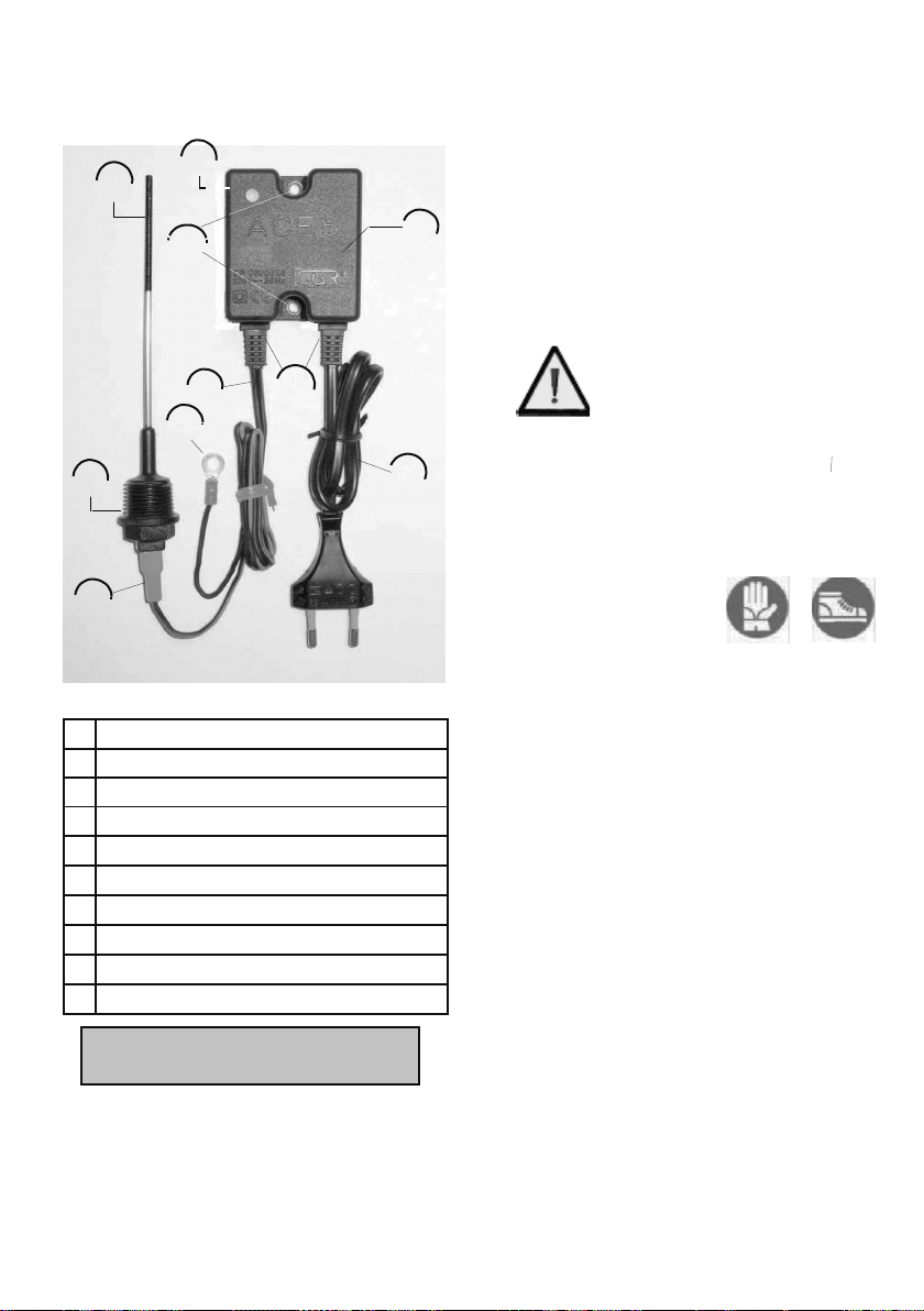
1
generator
2
power
cable
3
low
tension cable
4
earth
5
anode
holder
cap
6
anode
7
female
faston
8
operation
green
-
red
LED
9
cable
glands
10
eyelets
for
assembly
At the time of shipment the products
are packed inside special cardboard
containers.
The integrity of the contents during
transport is obtained by placing
protection material such as
polystyrene inside the packing.
The weight of the load to be handled
is always specified on the outside of
the packing.
With large supplies, the weight of the
load may exceed 30 kg.
In this case the loads must
not be handled manually.
Carry out these activities
using special lifting tools.
During manual handling (in case of
loads of less than 30 kg to be
handled) the personnel engaged in
this activity must wear safety shoes
and protective gloves.
The supply consists of:
- anodes (in the quantity required by
the customer and in the types
agreed on according to customer
needs)
- generator
- power cable
- low tension cable
- earth
- cap holder
- anode holder cap
- female faston
- operation LED (green and red)
- possible single-core cable for
2nd anode (if requested by
customer)
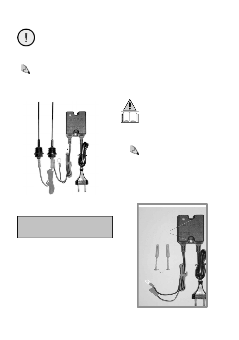
- cable glands and eyelet for
installation (present only in the
ACES device) (figure 2 on next
page).
9.1 WARRANTY SERVICES
ACES line products are covered for the
period envisaged for the European
guarantee (2 years) starting from the
purchase invoice date . The warranty
entitles the purchaser to replacement
of the product or its repair (if feasible)
in case of any operation defects
occurring within 2 years of the date of
purchase.
9.2 WARRANTY PROVISIONS
If the validity of the warranty rights is
ascertained, the product will be
returned at the manufacturer’s
expense.
Replacement of the product is not
envisaged whenever the fault depends
on:
- incorrect or improper use;
- fraudulent tampering or behaviour by
the user contrary to the
manufacturer’s instructions referred
to in this manual;
- connection not complying with the
technical and safety regulations in
the user’s country;
- if the product was open or repaired
by the customer himself or by
unauthorised personnel.
If, on checking the device, it is
found that the present damage is
not covered by the warranty, the
cost incurred by such checking
shall be borne by the customer.
Products not covered by warranty
will only be repaired at the
customer’s expense.
If the lack of right to the warranty
is ascertained, MG ANODI will get
the opinion of the customer who
shall inform MG ANODI regarding
what to do
(if to proceed or not
with repair or
replacement at his
own expense).
Equipment used in the domestic
environment
According to the current European
regulations, electrical and electronic
equipment must be disposed of
differently from domestic waste.
Private individuals residing in
EU member countries have free access
to the special electrical/electronic
waste collection areas.
For more information contact the
authority in charge of disposal
operations for such products in your
country.
In some EU countries, when
purchasing a new product the local
dealer is obliged to collect the old
product. Contact the dealer for further
information.
Equipment used in workplaces
Even in case of equipment used in the
workplace, it must be disposed of in
compliance with the current
regulations in the country.
Current European regulations require
such types of waste to be disposed of
according to specific procedures.
Before carrying out disposal, contact
the dealer to find out if there are
specific collection programmes.
4
9
4. SUPPLY SPECIFICATIONS
6
8
10
1
3
9
4
5
2
7
figure 1
key
9. WARRANTY 10. INFORMATION
REGARDING DISPOSAL
1
generator
2
power
cable
3
low
tension cable
4
earth
5
anode
holder
cap
6
anode
7
female
faston
8
operation
green
-
red
LED
9
cable
glands
10
eyelets
for
assembly
At the time of shipment the products
are packed inside special cardboard
containers.
The integrity of the contents during
transport is obtained by placing
protection material such as
polystyrene inside the packing.
The weight of the load to be handled
is always specified on the outside of
the packing.
With large supplies, the weight of the
load may exceed 30 kg.
In this case the loads must
not be handled manually.
Carry out these activities
using special lifting tools.
During manual handling (in case of
loads of less than 30 kg to be
handled) the personnel engaged in
this activity must wear safety shoes
and protective gloves.
The supply consists of:
- anodes (in the quantity required by
the customer and in the types
agreed on according to customer
needs)
- generator
- power cable
- low tension cable
- earth
- cap holder
- anode holder cap
- female faston
- operation LED (green and red)
- possible single-core cable for
2nd anode (if requested by
customer)
- cable glands and eyelet for
installation (present only in the
ACES device) (figure 2 on next
page).
9.1 WARRANTY SERVICES
ACES line products are covered for the
period envisaged for the European
guarantee (2 years) starting from the
purchase invoice date . The warranty
entitles the purchaser to replacement
of the product or its repair (if feasible)
in case of any operation defects
occurring within 2 years of the date of
purchase.
9.2 WARRANTY PROVISIONS
If the validity of the warranty rights is
ascertained, the product will be
returned at the manufacturer’s
expense.
Replacement of the product is not
envisaged whenever the fault depends
on:
- incorrect or improper use;
- fraudulent tampering or behaviour by
the user contrary to the
manufacturer’s instructions referred
to in this manual;
- connection not complying with the
technical and safety regulations in
the user’s country;
- if the product was open or repaired
by the customer himself or by
unauthorised personnel.
If, on checking the device, it is
found that the present damage is
not covered by the warranty, the
cost incurred by such checking
shall be borne by the customer.
Products not covered by warranty
will only be repaired at the
customer’s expense.
If the lack of right to the warranty
is ascertained, MG ANODI will get
the opinion of the customer who
shall inform MG ANODI regarding
what to do
(if to proceed or not
with repair or
replacement at his
own expense).
Equipment used in the domestic
environment
According to the current European
regulations, electrical and electronic
equipment must be disposed of
differently from domestic waste.
Private individuals residing in
EU member countries have free access
to the special electrical/electronic
waste collection areas.
For more information contact the
authority in charge of disposal
operations for such products in your
country.
In some EU countries, when
purchasing a new product the local
dealer is obliged to collect the old
product. Contact the dealer for further
information.
Equipment used in workplaces
Even in case of equipment used in the
workplace, it must be disposed of in
compliance with the current
regulations in the country.
Current European regulations require
such types of waste to be disposed of
according to specific procedures.
Before carrying out disposal, contact
the dealer to find out if there are
specific collection programmes.
4
9
4. SUPPLY SPECIFICATIONS
6
8
10
1
3
9
4
5
2
7
figure 1
key
9. WARRANTY 10. INFORMATION
REGARDING DISPOSAL
ACES
FIXING
HOLES
PLASTIC PLUGS
SCREWS
figure
3.1
Non-compliance with these
instructions and therefore
inverting polarities annuls the
anticorrosive power of the
equipment.
Connect the power outlet after
making sure the mains current
matches the data given on the rating
plate of the device (Volt 230
±
10,
Hz. 50/60) and that the mains voltage
is applied continuously.
The power outlet is also used as a
disconnecting device.
Therefore it must be easily
accessible to the user.
For safety reasons, the tank
for heating the water must
not work for long periods
without water being drawn.
The power outlet cannot be
disconnected when the
heating tank is full,
otherwise the anticorrosion
protection is annulled.
As already illustrated, the ACES device
is equipped with a fault diagnosis
system with the LED on the box of the
device lighting up.
When started, if everything works
properly the LED of the device
lights up green.
If the LED lights up red, it means
there is a fault.
In this case, the user must:
- make sure there is water in the tank;
- make sure the power plug is
connected and that there is current;
- make sure the earth of the device’s
circuit is properly connected,
otherwise the circuit does not close
and the device cannot work.
8
If all the above checks gave
negative results and no faults
explaining lighting up of the red
LED were found, avoid carrying
out any activity and contact the
manufacturer
The above-mentioned device does not
require any kind of maintenance work.
In normal conditions and with correct
use it will work for decades.
MG ANODI INTERNATIONAL does
not provide for the supply of
spare
parts, because in normal conditions
and with correct use of the
device
none of its parts should wear
out to
the point of requiring replacement.
In case of specific requests by the
user, MG ANODI INTERNATIONAL can
supply any additional anodes with
respective single-core
cable.
The user must check the
contents of the supply upon
delivery.
In case of errors or
omissions, contact the manufactu-
rer.
Note:
The size of the anodes depends on the
capacity of the tank, with reference to
the DIN 4753 table.
figure 2: ACES device with double anode
5.1 Electronic device installation
The ACES device can be fixed to the
wall or ceiling (the method is the same
both for ACES and ACES G2).
In both cases, proceed as follows (see
figures 3.1 and 3.2):
- make two holes (in the wall or
ceiling) for inserting the fixing
screws.
- Insert plastic plugs, suitable for
fixing screws, in the two holes.
5
- Position the device, matching the
holes in the device with those obtained
in the wall or ceiling.
- Insert the fixing screws (of length
according to the depth of the holes
made and the type of product; ACES
requires larger screws, ACES G2
requires smaller screws).
- fix the screws and check the solidity
and tightness of the fixing.
5.2 Anode installation
To fit the anode on the tank, the
tank must be arranged to receive
the anode support, i.e. the tank
must be provided with a special
hole whose diameter must not be
less that 1/2”-conical gas for inserting
the anode.
Note:
If the diameter of the hole for the
anode is more than 1/2”, the anode
must be equipped with a special
reduction adapter to ensure its perfect
insertion inside the tank. The user must
procure the suitable galvanised
reduction adapter.
5. INSTALLATION AND
STARTUP
8. SPARE PARTS
7. MAINTENANCE
6. TROUBLESHOOTING
figure
4.1:
example
of
assembly
on boiler - exchanger
inlet hole
anode support
wall-mounted
generator
anode
anode
6
anode support inlet hole
anode
wall-mounted
generator
wall-mounted
generator
anode
anode support inlet hole
figure 3.2
FIXING
HOLES
PLASTIC
PLUGS AND
SCREWS
ACES G2
The anode is supplied protected
by a plastic protection. Remove
the protection before installing
the anode. The user must not
operate in any way on the activated part
of the anode (terminal end), to clean it or
other, since similar activities could
damage the anode, neutralising its
anticorrosive effectiveness.
5.4 Startup
After carrying out the steps described
above (the first two steps can also be
carried out in reverse order to that
described):
-1- Insert the anode inside the hole
arranged on the tank (with the aid of
figure 4.2: example of assembly in water
heater-horizontal anode
figure 4.2: example of assembly in
water heater-vertical anode
5.3 Device installation
For tanks up to 1000 l. a single
anode can be fitted.
The anode holder cap must be
inserted inside the tank hole (figures
4.1, 4.2, 4.3) directly or using a
special reduction adapter as
described above.
For the ACES device to correctly
carry out its anticorrosive function, it
must be fitted in the geometric
centre of the tank (whether fitted
vertically or horizontally).
In case of large tanks holding more
than 1,000 litres, two anodes must
be installed and, regarding the
surface to be protected, the tank is
virtually divided into 3 parts (see
fig. 4.1)
In this case the two anodes must be
positioned so that the distance
between anode and tank walls is the
same, in order to obtain total
anticorrosive coverage of all the area
involved.
a special reduction adapter in case of
a larger hole);
-2- fix the anode by screwing it on the
hole in the tank;
-3- insert the low tension cable (positive
polarity), called faston, on the
anode;
-4- connect the cable with eyelet
(negative polarity) to the tank earth.
Connection to the tank earth is carried
out by inserting the eyelet of the cable
with negative polarity inside a special
screw on the tank casing
Every tank has a screw for the earth
connection (it may be in different places
on the tank casing, depending on the
boiler manufacturer).
At the end of the operations
described, carry out the following
checks:
- make sure the tank is full of water
(the pressure must be regular; check
with a manometer); in case of lack of
water, suitably fill;
- ensure correct polarity of the cables:
the wire ending with the faston
contact (positive polarity) must be
connected to the anode; the wire
ending with the eyelet (negative
polarity) must be connected to the
tank earth.
figure 4.3: example of assembly on
7
boiler
with
coil
anode support inlet hole
wall
-
mounted
generator
anode

ACES
FIXING
HOLES
PLASTIC PLUGS
SCREWS
figure
3.1
Non-compliance with these
instructions and therefore
inverting polarities annuls the
anticorrosive power of the
equipment.
Connect the power outlet after
making sure the mains current
matches the data given on the rating
plate of the device (Volt 230
±
10,
Hz. 50/60) and that the mains voltage
is applied continuously.
The power outlet is also used as a
disconnecting device.
Therefore it must be easily
accessible to the user.
For safety reasons, the tank
for heating the water must
not work for long periods
without water being drawn.
The power outlet cannot be
disconnected when the
heating tank is full,
otherwise the anticorrosion
protection is annulled.
As already illustrated, the ACES device
is equipped with a fault diagnosis
system with the LED on the box of the
device lighting up.
When started, if everything works
properly the LED of the device
lights up green.
If the LED lights up red, it means
there is a fault.
In this case, the user must:
- make sure there is water in the tank;
- make sure the power plug is
connected and that there is current;
- make sure the earth of the device’s
circuit is properly connected,
otherwise the circuit does not close
and the device cannot work.
8
If all the above checks gave
negative results and no faults
explaining lighting up of the red
LED were found, avoid carrying
out any activity and contact the
manufacturer
The above-mentioned device does not
require any kind of maintenance work.
In normal conditions and with correct
use it will work for decades.
MG ANODI INTERNATIONAL does
not provide for the supply of
spare
parts, because in normal conditions
and with correct use of the
device
none of its parts should wear
out to
the point of requiring replacement.
In case of specific requests by the
user, MG ANODI INTERNATIONAL can
supply any additional anodes with
respective single-core
cable.
The user must check the
contents of the supply upon
delivery.
In case of errors or
omissions, contact the manufactu-
rer.
Note:
The size of the anodes depends on the
capacity of the tank, with reference to
the DIN 4753 table.
figure 2: ACES device with double anode
5.1 Electronic device installation
The ACES device can be fixed to the
wall or ceiling (the method is the same
both for ACES and ACES G2).
In both cases, proceed as follows (see
figures 3.1 and 3.2):
- make two holes (in the wall or
ceiling) for inserting the fixing
screws.
- Insert plastic plugs, suitable for
fixing screws, in the two holes.
5
- Position the device, matching the
holes in the device with those obtained
in the wall or ceiling.
- Insert the fixing screws (of length
according to the depth of the holes
made and the type of product; ACES
requires larger screws, ACES G2
requires smaller screws).
- fix the screws and check the solidity
and tightness of the fixing.
5.2 Anode installation
To fit the anode on the tank, the
tank must be arranged to receive
the anode support, i.e. the tank
must be provided with a special
hole whose diameter must not be
less that 1/2”-conical gas for inserting
the anode.
Note:
If the diameter of the hole for the
anode is more than 1/2”, the anode
must be equipped with a special
reduction adapter to ensure its perfect
insertion inside the tank. The user must
procure the suitable galvanised
reduction adapter.
5. INSTALLATION AND
STARTUP
8. SPARE PARTS
7. MAINTENANCE
6. TROUBLESHOOTING
1
generator
2
power
cable
3
low
tension cable
4
earth
5
anode
holder
cap
6
anode
7
female
faston
8
operation
green
-
red
LED
9
cable
glands
10
eyelets
for
assembly
At the time of shipment the products
are packed inside special cardboard
containers.
The integrity of the contents during
transport is obtained by placing
protection material such as
polystyrene inside the packing.
The weight of the load to be handled
is always specified on the outside of
the packing.
With large supplies, the weight of the
load may exceed 30 kg.
In this case the loads must
not be handled manually.
Carry out these activities
using special lifting tools.
During manual handling (in case of
loads of less than 30 kg to be
handled) the personnel engaged in
this activity must wear safety shoes
and protective gloves.
The supply consists of:
- anodes (in the quantity required by
the customer and in the types
agreed on according to customer
needs)
- generator
- power cable
- low tension cable
- earth
- cap holder
- anode holder cap
- female faston
- operation LED (green and red)
- possible single-core cable for
2nd anode (if requested by
customer)
- cable glands and eyelet for
installation (present only in the
ACES device) (figure 2 on next
page).
9.1 WARRANTY SERVICES
ACES line products are covered for the
period envisaged for the European
guarantee (2 years) starting from the
purchase invoice date . The warranty
entitles the purchaser to replacement
of the product or its repair (if feasible)
in case of any operation defects
occurring within 2 years of the date of
purchase.
9.2 WARRANTY PROVISIONS
If the validity of the warranty rights is
ascertained, the product will be
returned at the manufacturer’s
expense.
Replacement of the product is not
envisaged whenever the fault depends
on:
- incorrect or improper use;
- fraudulent tampering or behaviour by
the user contrary to the
manufacturer’s instructions referred
to in this manual;
- connection not complying with the
technical and safety regulations in
the user’s country;
- if the product was open or repaired
by the customer himself or by
unauthorised personnel.
If, on checking the device, it is
found that the present damage is
not covered by the warranty, the
cost incurred by such checking
shall be borne by the customer.
Products not covered by warranty
will only be repaired at the
customer’s expense.
If the lack of right to the warranty
is ascertained, MG ANODI will get
the opinion of the customer who
shall inform MG ANODI regarding
what to do
(if to proceed or not
with repair or
replacement at his
own expense).
Equipment used in the domestic
environment
According to the current European
regulations, electrical and electronic
equipment must be disposed of
differently from domestic waste.
Private individuals residing in
EU member countries have free access
to the special electrical/electronic
waste collection areas.
For more information contact the
authority in charge of disposal
operations for such products in your
country.
In some EU countries, when
purchasing a new product the local
dealer is obliged to collect the old
product. Contact the dealer for further
information.
Equipment used in workplaces
Even in case of equipment used in the
workplace, it must be disposed of in
compliance with the current
regulations in the country.
Current European regulations require
such types of waste to be disposed of
according to specific procedures.
Before carrying out disposal, contact
the dealer to find out if there are
specific collection programmes.
4
9
4. SUPPLY SPECIFICATIONS
6
8
10
1
3
9
4
5
2
7
figure 1
key
9. WARRANTY 10. INFORMATION
REGARDING DISPOSAL
ACES
FIXING
HOLES
PLASTIC PLUGS
SCREWS
figure
3.1
Non-compliance with these
instructions and therefore
inverting polarities annuls the
anticorrosive power of the
equipment.
Connect the power outlet after
making sure the mains current
matches the data given on the rating
plate of the device (Volt 230
±
10,
Hz. 50/60) and that the mains voltage
is applied continuously.
The power outlet is also used as a
disconnecting device.
Therefore it must be easily
accessible to the user.
For safety reasons, the tank
for heating the water must
not work for long periods
without water being drawn.
The power outlet cannot be
disconnected when the
heating tank is full,
otherwise the anticorrosion
protection is annulled.
As already illustrated, the ACES device
is equipped with a fault diagnosis
system with the LED on the box of the
device lighting up.
When started, if everything works
properly the LED of the device
lights up green.
If the LED lights up red, it means
there is a fault.
In this case, the user must:
- make sure there is water in the tank;
- make sure the power plug is
connected and that there is current;
- make sure the earth of the device’s
circuit is properly connected,
otherwise the circuit does not close
and the device cannot work.
8
If all the above checks gave
negative results and no faults
explaining lighting up of the red
LED were found, avoid carrying
out any activity and contact the
manufacturer
The above-mentioned device does not
require any kind of maintenance work.
In normal conditions and with correct
use it will work for decades.
MG ANODI INTERNATIONAL does
not provide for the supply of
spare
parts, because in normal conditions
and with correct use of the
device
none of its parts should wear
out to
the point of requiring replacement.
In case of specific requests by the
user, MG ANODI INTERNATIONAL can
supply any additional anodes with
respective single-core
cable.
The user must check the
contents of the supply upon
delivery.
In case of errors or
omissions, contact the manufactu-
rer.
Note:
The size of the anodes depends on the
capacity of the tank, with reference to
the DIN 4753 table.
figure 2: ACES device with double anode
5.1 Electronic device installation
The ACES device can be fixed to the
wall or ceiling (the method is the same
both for ACES and ACES G2).
In both cases, proceed as follows (see
figures 3.1 and 3.2):
- make two holes (in the wall or
ceiling) for inserting the fixing
screws.
- Insert plastic plugs, suitable for
fixing screws, in the two holes.
5
- Position the device, matching the
holes in the device with those obtained
in the wall or ceiling.
- Insert the fixing screws (of length
according to the depth of the holes
made and the type of product; ACES
requires larger screws, ACES G2
requires smaller screws).
- fix the screws and check the solidity
and tightness of the fixing.
5.2 Anode installation
To fit the anode on the tank, the
tank must be arranged to receive
the anode support, i.e. the tank
must be provided with a special
hole whose diameter must not be
less that 1/2”-conical gas for inserting
the anode.
Note:
If the diameter of the hole for the
anode is more than 1/2”, the anode
must be equipped with a special
reduction adapter to ensure its perfect
insertion inside the tank. The user must
procure the suitable galvanised
reduction adapter.
5. INSTALLATION AND
STARTUP
8. SPARE PARTS
7. MAINTENANCE
6. TROUBLESHOOTING

ACES TECHNICAL CARD
Generator dimensions:
an impressed current electronic device
for cathodic
protection against corrosion
in
enamelled /
vitrified
boilers of up to 5,000 litres capacity.
Technical characteristics:
Power supply
Voltage:
230 Volt ± 10%
Frequency:
50/60 Hz
max. output voltage: 13VDC
max. output current: 0.25 A
protection rating: IP 55
max. input: 4.5 W
operating temperature from 0 to 50°
double electrical insulation
Generator dimensions:
nominal external dimensions of generator: 60x52x45 mm.
weight:
approx. 0.40 kg
cable with flat plug: length 1900 mm
low tension cable: length 1900 mm
TITANIUM ELECTRODE (ACES AND ACES G2)
Description of the product:
a current delivery and
measurement device with coating in noble metal.
Size of electrodes:
various sizes depending on the
characteristics of the tanks to be protected
size of treated part: 3 mm
For stainless steel, MG ANODI INTERNATIONAL will prepare a
design according to the
characteristics and capacity of the boiler.
Maintaining of the potential is
guaranteed through constant
periodical measurement of the
difference in potential between the
boiler and the titanium anode.
According to measurement results, the
electronic device of the equipment
adjusts the current potential the
titanium anode must deliver in order to
guarantee optimum protection against
corrosion.
The anode consists of a 3 mm
diameter titanium rod (figure 1 on next
page).
One of the two ends of the anode is
treated by means of an
electrochemical activation process
<6> and the other non-activated end
is equipped with a threaded cap in
special plastic material of diameter
1/2”, conical gas <5>.
Only the terminal end of the anode
(whose length can vary) is
electrochemically activated and able to
impress current, whereas the other
part of the anode does not undergo the
above-mentioned treatment and its
purpose is to convey the current near
the activated area. The electronic
device is housed in a plastic container
resistant to high temperatures <1>.
Correct operation of the device is
monitored by a special sensor and
indicated by a LED located in the front
of the equipment <8>.
If the LED lights up green it
means that the device is
working properly; if it lights up
red, the LED signals an operation
fault.
The correct polarity of the
cables
must
be
strictly
respected during
the
installation stage: the wire
ending with the faston contact
(positive polarity) must be connected
to the anode; the wire ending with the
eyelet (negative polarity) must be
connected to the tank earth.
Failure to comply with this instruction
implies improper use and invalidates
the warranty.
Also, the earth (eyelet) must be
secured to the tank.
The earth (eyelet) MUST NEVER be
connected to the pipes entering or
leaving the tank.
3.1 Permissible/improper use
The device in question must only be
used as an anticorrosion device for
enamelled/vitrified boilers or boilers in
stainless steel. It cannot be used for
different types of boilers and must be
installed and used according to the
instructions given in this handbook.
Any use different from that for which
the product is intended and any non-
compliance with the instructions given
in this handbook implies non-
compliance with the product’s
intended use.
The manufacturer declines
any liability for damage or
injury caused by improper
and non-conforming use of
the product.
3

This handbook must be consulted by
the customer for correct installation
and use of the product.
The user must strictly comply with the
safety instructions given in it.
The manufacturer declines any liability
for injury or damage due to improper
use (§ 3) of the product and/or failure
to apply the rules for safe operation
described in this handbook.
Keeping the handbook
This handbook must be kept carefully
and in good condition by the user.
If it is lost, the user can request a new
copy from the manufacturer on
payment.
Given below are the symbols present
in this publication, together with their
respective meanings.
READ THE MANUAL CAREFULLY
indicates cases or situations
where the user must refer to
the instructions present in the
manual in order to carry out a
given operation correctly and
safely.
WARNING
The warning messages
indicate the risk of accident
or danger during operation or
maintenance work, if the procedures
and conditions described are not
carefully observed.
ATTENTION
The attention messages
indicate risk of damage to
the equipment during operation or
maintenance work, if the procedures
and conditions described are not
carefully observed.
NOTE: The notes bring the
user’s attention to important
information regarding the matter,
application or procedure.
The ACES device is an impressed
current cathodic protection electronic
system for boilers and water heaters.
Its purpose is to annul the corrosive
effect that the water would have on
the tank lining.
It is also extremely effective against
the presence of microorganisms
harmful to health, such as legionella
pneumophila. There are two product
types: ACES and ACES G2, which
differ for the type of application.
ACES is installed on enamelled and
vitrified boilers of up to 5,000 litres
capacity.
ACES G2 is always installed on the
same types of boilers, with capacities
of up to 1,000 litres. In case of
unfavourable conditions or containers
holding more than 5,000 litres, the
use of two or more generators is
provided for. The ACES system
provides cathodic protection against
corrosion, obtained by ensuring the
potential of the electrolyte by means
of an impressed current produced by
the device.
ACES G2 TECHNICAL CARD
For stainless steel, MG ANODI INTERNATIONAL will prepare a
design according to the
characteristics and capacity of the boiler.
2
3. DESCRIPTION OF PRODUCT
PERMISSIBLE/
IMPROPER USE
2. SYMBOLS
Description of the product:
an impressed current electronic
device for cathodic protection against corrosion in enamelled /
vitrified boilers of up to 1,000 litres capacity.
Electrical characteristics:
Power supply
Voltage:
230 ± 10% Volt
Frequency:
50/60 Hz
max. output voltage: 16VDC
max. output current: 0.13 A
protection rating: IP 55
max. input: 3.2 W
Generator dimensions:
nominal external dimensions of generator: 60x52x35.5 mm.
weight:
approx. 0.26 kg
cable with flat plug: length 1900 mm
low tension cable: length 1900 mm
TITANIUM ELECTRODE (ACES AND ACES G2)
Description of the product:
a current delivery and
measurement device with coating in noble metal
Size of electrodes:
various lengths depending on the
characteristics of the tanks to be protected
size of treated part: 3 mm
ACES TECHNICAL CARD
Generator dimensions:
an impressed current electronic device
for cathodic
protection against corrosion
in
enamelled /
vitrified
boilers of up to 5,000 litres capacity.
Technical characteristics:
Power supply
Voltage:
230 Volt ± 10%
Frequency:
50/60 Hz
max. output voltage: 13VDC
max. output current: 0.25 A
protection rating: IP 55
max. input: 4.5 W
operating temperature from 0 to 50°
double electrical insulation
Generator dimensions:
nominal external dimensions of generator: 60x52x45 mm.
weight:
approx. 0.40 kg
cable with flat plug: length 1900 mm
low tension cable: length 1900 mm
TITANIUM ELECTRODE (ACES AND ACES G2)
Description of the product:
a current delivery and
measurement device with coating in noble metal.
Size of electrodes:
various sizes depending on the
characteristics of the tanks to be protected
size of treated part: 3 mm
For stainless steel, MG ANODI INTERNATIONAL will prepare a
design according to the
characteristics and capacity of the boiler.
Maintaining of the potential is
guaranteed through constant
periodical measurement of the
difference in potential between the
boiler and the titanium anode.
According to measurement results, the
electronic device of the equipment
adjusts the current potential the
titanium anode must deliver in order to
guarantee optimum protection against
corrosion.
The anode consists of a 3 mm
diameter titanium rod (figure 1 on next
page).
One of the two ends of the anode is
treated by means of an
electrochemical activation process
<6> and the other non-activated end
is equipped with a threaded cap in
special plastic material of diameter
1/2”, conical gas <5>.
Only the terminal end of the anode
(whose length can vary) is
electrochemically activated and able to
impress current, whereas the other
part of the anode does not undergo the
above-mentioned treatment and its
purpose is to convey the current near
the activated area. The electronic
device is housed in a plastic container
resistant to high temperatures <1>.
Correct operation of the device is
monitored by a special sensor and
indicated by a LED located in the front
of the equipment <8>.
If the LED lights up green it
means that the device is
working properly; if it lights up
red, the LED signals an operation
fault.
The correct polarity of the
cables
must
be
strictly
respected during
the
installation stage: the wire
ending with the faston contact
(positive polarity) must be connected
to the anode; the wire ending with the
eyelet (negative polarity) must be
connected to the tank earth.
Failure to comply with this instruction
implies improper use and invalidates
the warranty.
Also, the earth (eyelet) must be
secured to the tank.
The earth (eyelet) MUST NEVER be
connected to the pipes entering or
leaving the tank.
3.1 Permissible/improper use
The device in question must only be
used as an anticorrosion device for
enamelled/vitrified boilers or boilers in
stainless steel. It cannot be used for
different types of boilers and must be
installed and used according to the
instructions given in this handbook.
Any use different from that for which
the product is intended and any non-
compliance with the instructions given
in this handbook implies non-
compliance with the product’s
intended use.
The manufacturer declines
any liability for damage or
injury caused by improper
and non-conforming use of
the product.
3

DICHIARAZIONE DI CONFORMITA’/
DECLARATION OF CONFORMITY
Fabbricante/Manufacturer:
MG ANODI INTERNATIONAL AD
Velikotarnovsko Shosse 1
5400 Sevlievo – Bulgaria
Descrizione del prodotto/
Product(s) description: Dispostivo elettronico anticorrosione per
bollitori/Electronic devices for boilers and
water-heaters corrosion prevention:
Modello (i)/Model(s): A C E S Serie H
A C E S G 2
Si certifica sotto la nostra esclusiva responsabilità che i prodotti a cui si riferisce la
presente dichiarazione sono conformi alle seguenti Direttive europee/
We hereby certify under our sole responsability, that the product(s) to which this
declaration relates is/are in conformity with the requirements of the following
European Directives:
Council Directive 89/336/EEC Directive (Electromagnetic Compatibility),
Council Directive73/23EEC Directive (Low Voltage Equipement Safety)
Council Directive 2001/95/EC Directive (General Product Safety).
E alle seguenti norme armonizzate / and with the following European Standards
CONTENTS
1 Using the manual 1
2 Symbols 2
3 Description of the product
3.1 Permissible/improper use
3
4 Supply specifications 4
5 Installation and startup 5
5.1 Electronic device installation
5
5.2 Anode installation
5
5.3 Device installation
5.4 Startup
6
6 Troubleshooting 8
7 Maintenance 8
8 Spare parts 8
9 Warranty 9
10 Instructions regarding disposal 9
ACES - ACES G2 technical card 10-11
Manufacturer’s declaration of conformity 12
English
EN 60065 (2004):Audio, video and similair electronic apparatus Safety
requirements
EN 55011 (2011) CISPR 11/A1:2010-03 ;
EN 61000-4-3 (2007)- radiated immunity (10V/m,80-1000MHz, AM 80%)
EN 61000-4-6 (2011) - conducted RF immunity (10Vrms,0.15-80MHz,AM80%)
EN 61000-4-2 (2011) - electrostatic discharge (8 KV air, 4 KV contact)
EN 61000-4-4/A1 (2010) - BURST (2 KV, 5 kHz)
EN 61000-3-2/A1/A2 (2011) - harmonic current emissions
Sevlievo, 01/07/2016
Luca De Stefani, General Manager
Introduction
These operating instructions apply
to the products called ACES and
ACES G2.
The ACES device is an impressed
current cathodic protection system
for enamelled/vitrified or stainless
steel boilers of up to 5,000 litres
capacity.
The ACES G2 device is also an
impressed current cathodic
protection system for enamelled/
vitrified boilers of up to 1,000 litres
capacity.
This instruction handbook always comes
with the product, and is placed inside
the packing.
The last page of this handbook contains
the manufacturer’s declaration of
conformity, which must be kept by the
user together with the handbook and
shown to the competent supervisory
authority on the occasion of any checks
or inspections.
1
1. USING THE INSTRUCTIONS
This manual suits for next models
1
Table of contents


