MG 47LV User manual

EM-9502-A Rev.7 P. 1 / 5
MG CO., LTD. www.mgco.jp
5-2-55 Minamitsumori, Nishinari-ku, Osaka 557-0063 JAPAN
INSTRUCTION MANUAL
DC INPUT DIGITAL PANEL METER
(4 1/2 digit, LED display type) MODEL 47LV
BEFORE USE ....
Thank you for choosing us. Before use, please check con-
tents of the package you received as outlined below.
If you have any problems or questions with the product,
please contact our sales office or representatives.
■PACKAGE INCLUDES:
Digital panel meter
(body + mounting bracket × 2 + watertight packing)........(1)
Engineering unit sticker label sheet..................................(1)
■MODEL NO.
Confirm Model No. marking on the product to be exactly
what you ordered.
■INSTRUCTION MANUAL
This manual describes necessary points of caution when
you use this product, including installation, connection and
basic maintenance procedures.
For detailed explanations to operate and program the mod-
ule, please refer to Model 47LV Operating Manual (EM-
9502-B), downloadable at our web site.
2.00 marked parameters are usable with the product ver-
sion 2.00 or higher.
POINTS OF CAUTION
■CONFORMITY WITH EU DIRECTIVES
• This equipment is suitable for Pollution Degree 2, Meas-
urement category II (alarm output, transient voltage
2500V) and Installation Category II (transient voltage
2500V). Reinforced insulation (input or DC output to
alarm output to power: 300V) and basic insulation (input
to DC output: 300V) are maintained. Prior to installation,
check that the insulation class of this unit satisfies the
system requirements.
• Altitude up to 2000 meters.
• The equipment must be installed such that appropriate
clearance and creepage distances are maintained to con-
form to CE requirements. Failure to observe these re-
quirements may invalidate the CE conformance.
• The actual installation environments such as panel con-
figurations, connected devices, connected wires, may af-
fect the protection level of this unit when it is integrated
in a panel system. The user may have to review the CE
requirements in regard to the whole system and employ
additional protective measures to ensure the CE conform-
ity.
• In order to enable the operator to turn off the power in-
put immediately, install a switch or a circuit breaker ac-
cording to the relevant requirements in IEC 60947-2 and
properly indicate it.
■POWER INPUT RATING & OPERATIONAL RANGE
• Locate the power input rating marked on the product and
confirm its operational range as indicated below:
100 – 240V AC rating: 85 – 264V, 50/60 Hz, approx. 6.5VA
24V DC rating: 24V ±10%, approx. 3W
110V DC rating: 85 – 150V, approx. 3W
■GENERAL PRECAUTIONS
• Before you remove the unit or mount it, turn off the power
supply and input signal for safety.
• Be sure to put the terminal cover on while the power is
supplied.
■ENVIRONMENT
• Indoor use.
• When heavy dust or metal particles are present in the
air, install the unit inside proper housing with sufficient
ventilation.
• Do not install the unit where it is subjected to continuous
vibration. Do not subject the unit to physical impact.
• Environmental temperature must be within -10 to +55°C
(14 to 131°F) with relative humidity within 30 to 90% RH
in order to ensure adequate life span and operation.
• Be sure that the ventilation slits are not covered with ca-
bles, etc.
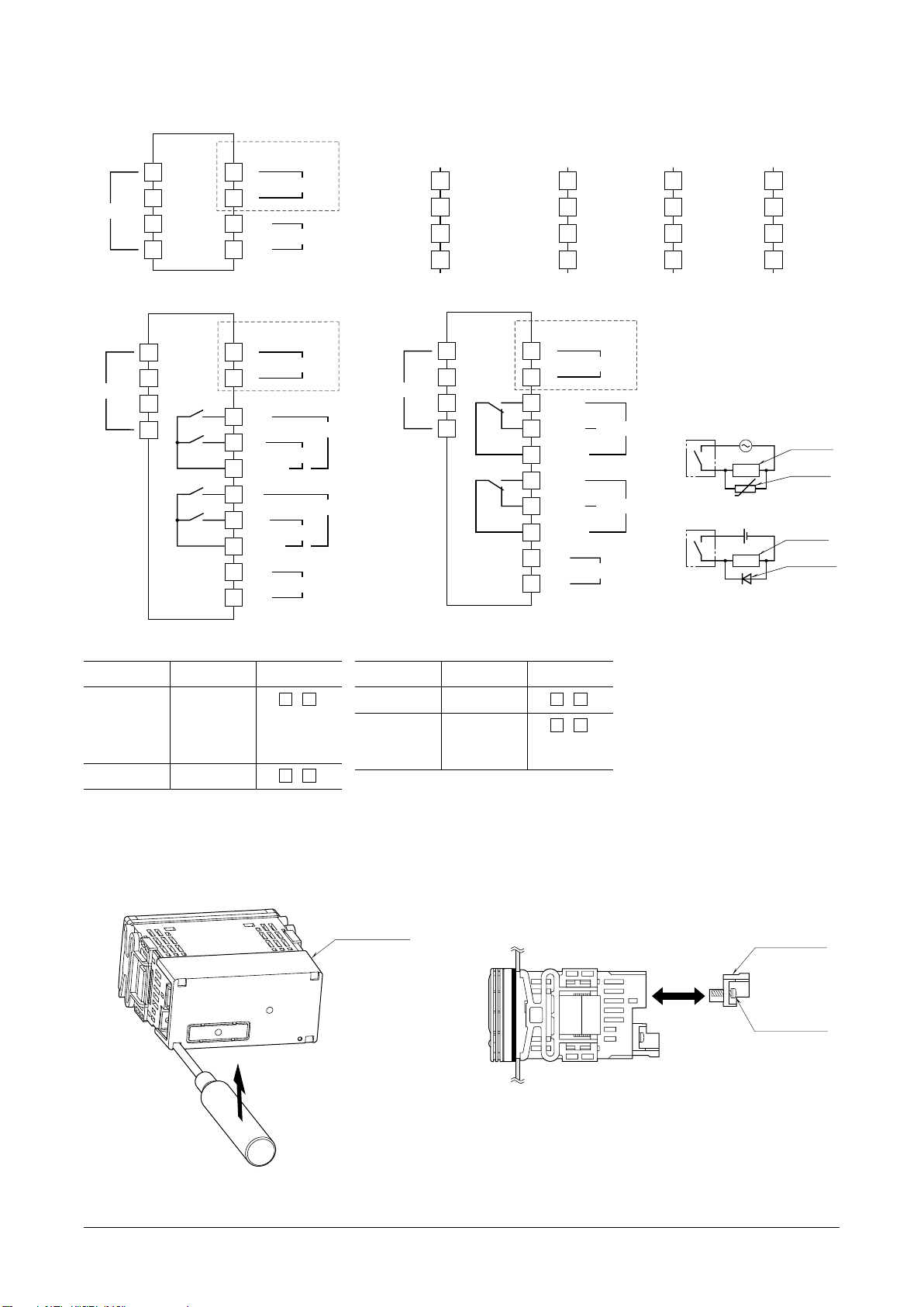
■REQUIREMENTS TO ENSURE IP66
• Observe the designated panel cutout size (W92 ×H45
mm).
• The watertight packing included in the product package
must be placed behind the front cover.
• Both mounting brackets must be fastened tightly until
they hit the panel.
• Confirm visually that the packing is not contorted or ex-
cessively run off the edge after installation.
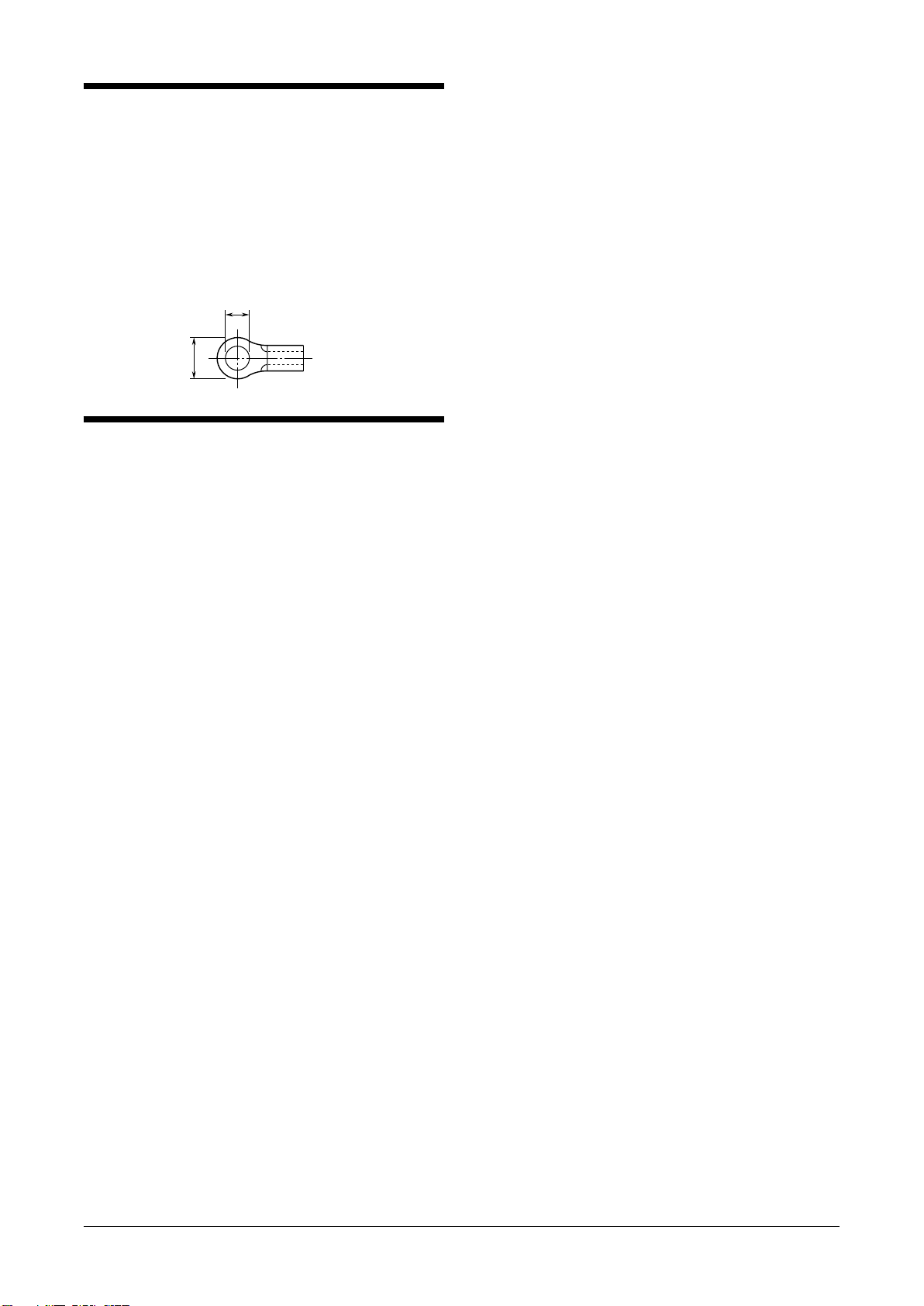
■WIRING
• Make sure for safety that only qualified personnel per-
form the wiring.
• Do not install cables close to noise sources (high frequen-
cy line, etc.).
• Do not bind these cables together with those in which
noises are present. Do not install them in the same duct.
■EX-FACTORY SETTING (/SET)
• Activating “initialization” of Lockout Setting Mode, Ex-
factory settings or user’s specified parameters will be
deleted and overwritten with the factory default values.
Notice that after this, Ex-factory settings will be irrecov-
erable.
■AND ....
• The unit is designed to function as soon as power is sup-
plied, however, a warm up for 10 minutes is required for
satisfying complete performance described in the data
sheet.

47LV
EM-9502-A Rev.7 P. 2 / 5
MG CO., LTD. www.mgco.jp
5-2-55 Minamitsumori, Nishinari-ku, Osaka 557-0063 JAPAN
COMPONENT IDENTIFICATION
Specifications
Strap
Watertight Packing
n TOP VIEW
n FRONT VIEW
n SIDE VIEW
Mounting Bracket Terminal Cover
(4) Max/Min Button
(5) Alarm/ Button
(6) Scale/ Button
(7) Shift Button
(8) Up Button
(1) Main Display
(2) Alarm Indicators
(3) Function Indicators
Alarm/ Scale/Max/Min Shift Up
Zro
HH
H
P
L
LL
Spn D/P
TchFnc Min Max
• COMPONENT IDENTIFICATION
No. COMPONENT FUNCTION
(1) Main display Indicates present values, setting values and status of the unit.
(2) Alarm indicators *1Indicate alarm status of the input signal.
LL turns on when the LL alarm is tripped.
L turns on when the L alarm is tripped.
H turns on when the H alarm is tripped.
HH turns on when the HH alarm is tripped.
P turns on when none of the other alarms is tripped.
(3) Function indicators Indicate the status in each setting mode.
(4) Max/Min button Used to switch the main display to show the present values, maximum values or minimum values etc.
(5) Alarm/ button Used to confirm alarm setting value and to move on to the alarm and other setting modes; or to shift
through setting items in each setting mode.
(6) Scale/ button Used to move on to the scaling and other setting modes; or to shift through setting items in each set-
ting mode.
(7) Shift button Used to move on to the setting standby status of each setting mode and shift through display digits in
each setting item.
(8) Up button Used to change setting values, to execute/cancel Forced Zero or to select setting values.
*1. Only the ‘P’ indicator turns on with no-alarm-output type. ‘LL’ or ‘HH’ does not turn on with dual-alarm-output type.
All setpoints can be independently set either for Hi or Lo alarm trip.

47LV
EM-9502-A Rev.7 P. 3 / 5
MG CO., LTD. www.mgco.jp
5-2-55 Minamitsumori, Nishinari-ku, Osaka 557-0063 JAPAN
INSTALLATION
92
+ 0.8
– 0
45
+ 0.6
– 0
min. 120
min. 75
Panel thickness: 1.6 to 8.0 mm
■HOW TO MOUNT THE UNIT ON A PANEL
The watertight packing must be in place to hold the meter.
Do not remove it.
1) Insert the unit into the panel cutout.
2) Push the mounting brackets into the grooves on both
sides of the rear module, until they hit the panel’s rear
side.
Mounting BracketWatertight packing Panel
TERMINAL CONNECTIONS
Connect the unit as in the diagram in the following page or refer to the connection diagram on the terminal cover.
■EXTERNAL DIMENSIONS unit: mm (inch)
96 (3.78)
48 (1.89)
103 (4.06)
95 (3.74)
2 (.08)
47 (1.85)
86 (3.39)12.5 (.49)
98.5 (3.88)
45 (1.77)
91.5 (3.60)
4–M3 SCREW
■REAR VIEW
• No Alarm Output • Alarm Output
■FRONT VIEW ■SIDE VIEW
■TOP VIEW
1234567891012345678910
11 12 13 14 15 16 17 18 19 20
20–M3 SCREW
TERMINAL
2–M3 SCREW
10–M3 SCREW
TERMINAL
6.6 (.26)

47LV
EM-9502-A Rev.7 P. 4 / 5
MG CO., LTD. www.mgco.jp
5-2-55 Minamitsumori, Nishinari-ku, Osaka 557-0063 JAPAN
■CONNECTION DIAGRAM
1
9
10
POWER
U(+)
V(–)
17
15
16
■
ALARM OUTPUT CODE 1: N.O. contact, 4 points
20
18
19
1
2
3
4
9
10
INPUT
POWER
U(+)
Lc (
COM
)
Lb (NC)
La (NO)
Hc (
COM
)
Hb (NC)
Ha (NO)
V(–)
17
15
16
■ALARM OUTPUT CODE 2: SPDT contact, 2 points
20
18
19
Lc, LLc
LLa
La
Hc, HHc
Ha
HHa
2
3
4
INPUT
LL OUTPUT
L OUTPUT
H OUTPUT
L OUTPUT
H OUTPUT
HH OUTPUT
1
9
10
POWER
U(+)
V(–)
■
ALARM OUTPUT CODE 0: No alarm output
2
3
4
INPUT
DC OUTPUT
7
8
+
–
DC OUTPUT
7
8
+
–
DC OUTPUT
7
8
+
–
LOAD
Inductive
Load (Coil)
Varistor or
CR Circuit
• DC Powered
LOAD
Inductive
Load (Coil)
Diode, Varisto
r
or CR Circuit
■Relay Protection
• AC Powered
Note: The section enclosed by broken line is only with DC output option.
+
+
+
V1
V2
I
COM –
1
3
2
4
+
+
V
I
COM –
1
3
2
4
+
––
1
3
2
4
+1
3
2
4
• Input code: 1, 2 • Input code: 3 • Input code: 4• Input code : 5, 6
U
• Input Terminal Assignments
INPUT TYPE MEASURING INPUT
(indicator) RANGE TERMINALS
V200 ±200V 1 – 4
V10 ±10V
V5 ±5V
V1 ±1V
V01 ±100mV 2 – 4
V001 ±10mV
INPUT TYPE MEASURING INPUT
(indicator) RANGE TERMINALS
V0-5 0 –5V 2 – 4
V1-5 1 –5V
A100 ±100mA 3 – 4
A1 ±1mA
A0-2 0 – 20mA
A4-2 4 – 20mA
A2-2 ±2A
A1-1 ±1A
V700 ±700V A01 ±100μA
■TERMINAL BLOCK
• How to remove the terminal cover
Insert the minus tip of a screwdriver into each hole at the
four corners of the cover and pull it to the direction as
indicated below to separate the terminal cover.
Terminal Cover
• How to remove the terminal block
The terminal block is separable in two pieces. Loosen two
screws on both sides of the terminal block to separate.
Be sure to turn off the power supply, input signal and
power supply to the output relays before separating the
terminal block.
Separable
Terminal Block
Terminal Block
Screw

47LV
EM-9502-A Rev.7 P. 5 / 5
MG CO., LTD. www.mgco.jp
5-2-55 Minamitsumori, Nishinari-ku, Osaka 557-0063 JAPAN
WIRING INSTRUCTIONS
■SCREW TERMINAL
Torque: 0.6 N·m
■SOLDERLESS TERMINAL
Refer to the drawing below for recommended ring tongue
terminal size. Spade tongue type is also applicable.
Applicable wire size: 0.25 to 1.65 mm2(AWG 22 to 16)
Recommended manufacturer: Japan Solderless Terminal
MFG.Co.Ltd, Nichifu Co.,ltd
6 (.24) max
3.3 (.13) max
mm (inch)
LIGHTNING SURGE PROTECTION
We offer a series of lightning surge protectors for protec-
tion against induced lightning surges. Please contact us to
choose appropriate models.
Table of contents
Other MG Measuring Instrument manuals