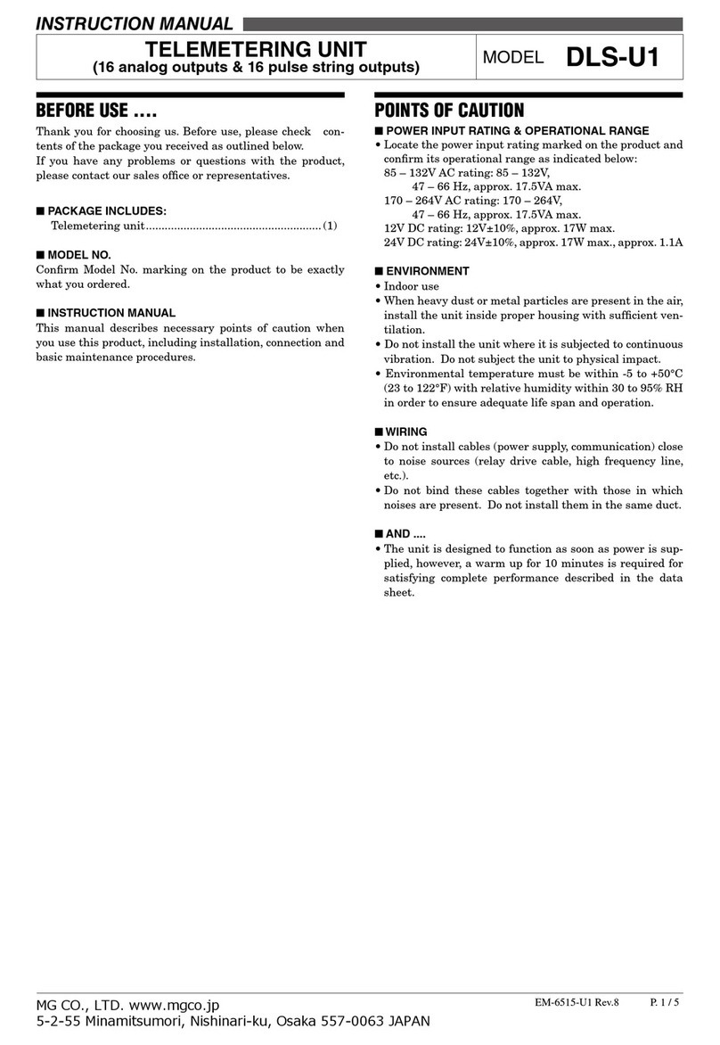
MG DLS-C1 User manual

DLS-qC1
P. 1 / 5EM-6515-C1 Rev.8
MG CO., LTD. www.mgco.jp
5-2-55 Minamitsumori, Nishinari-ku, Osaka 557-0063 JAPAN
TELEMETERING UNIT
(32 relay outputs) MODEL DLS-C1
INSTRUCTION MANUAL
BEFORE USE ....
Thank you for choosing us. Before use, please check
contents of the package you received as outlined below.
If you have any problems or questions with the product,
please contact our sales office or representatives.
■ PACKAGE INCLUDES:
Telemetering unit........................................................ (1)
■MODEL NO.
Confirm Model No. marking on the product to be exactly
what you ordered.
■INSTRUCTION MANUAL
This manual describes necessary points of caution when
you use this product, including installation, connection and
basic maintenance procedures.
POINTS OF CAUTION
■POWER INPUT RATING & OPERATIONAL RANGE
• Locate the power input rating marked on the product and
confirm its operational range as indicated below:
85 – 132V AC rating: 85 – 132V,
47 – 66 Hz, approx. 17.5VA max.
170 – 264V AC rating: 170 – 264V,
47 – 66 Hz, approx. 17.5VA max.
12V DC rating: 12V±10%, approx. 17W max.
24V DC rating: 24V±10%, approx. 17W max., approx. 1.1A
■ ENVIRONMENT
• Indoor use
• When heavy dust or metal particles are present in the air,
install the unit inside proper housing with sufficient ven-
tilation.
• Do not install the unit where it is subjected to continuous
vibration. Do not subject the unit to physical impact.
• Environmental temperature must be within -5 to +50°C
(23 to 122°F) with relative humidity within 30 to95% RH
in order to ensure adequate life span and operation.
■WIRING
• Do not install cables (power supply, communication) close
to noise sources (relay drive cable, high frequency line,
etc.).
• Do not bind these cables together with those in which
noises are present. Do not install them in the same duct.
■AND ....
• The unit is designed to function as soon as power is sup-
plied, however, a warm up for 10 minutes is required for
satisfying complete performance described in the data
sheet.

DLS-qC1
P. 2 / 5EM-6515-C1 Rev.8
MG CO., LTD. www.mgco.jp
5-2-55 Minamitsumori, Nishinari-ku, Osaka 557-0063 JAPAN
COMPONENT IDENTIFICATION
SA1
SA2
1
2
3
4
5
6
7
8
ON OFF
Transmission
Stop Bit
Data Bit
Parity
With/Without
Parity Check
14
25
1
13
■ DIP SWITCH
■ D-SUB CONNECTOR
PIN ASSIGNMENT
• RS-232-C Connection Example
(straight type cable)
FG
SD
RD
RS
CS
DR
SG
CD
ER
FG
SD
RD
RS
CS
DR
SG
CD
ER
1
2
3
4
5
6
7
8
20
1
2
3
4
5
6
7
8
20
DIP Switches
(Deleted with modem
type /A1)
Use straight type cable as in the diagram above.
Power LED Indicator
RUN LED Indicator
Station Address Setting
Rotary Switches
RS-232-C Connector
Connector
Unit Side
Connector
Modem Side
LEDI / O SECTION
TRANSMISSION SECTION
SA1
SA2
I / O SECTION
(See details to the right)
TRANSMISSION SECTION
(See details to the left)
9
8
7
6
5
4
3
2
1
JumperJumper
Fiber Link
Connector
•
TWISTED-PAIR & FIBER
40-terminal connector
5
4
3
2
1
Fiber Link
Connector
•FIBER OPTICS
9
8
7
6
5
4
3
2
1
•
TWISTED-PAIR
Fiber Link
Connector
2
4
6
8
10
12
14
16
18
20
22
24
26
28
30
32
34
36
38
40
1
3
5
7
9
11
13
15
17
19
21
23
25
27
29
31
33
35
37
39
Contact Output
Indicator LEDs
Euro Type
Connector
Terminals
Euro Type
Connector
Terminals
Euro Type
Connector
Terminals
■MULTIPLEX COMMUNICATION, PROCESS I/O, OUTPUT INDICATOR LEDS
SWITCH
NO.
TRANSMISSION SPEED (BPS)
300 600 1200 2400 4800 9600
1 OFF OFF OFF OFF ON ON
2 OFF OFF ON ON OFF OFF
3 OFF ON OFF ON OFF ON
SWITCH NO. 7 BITS 8 BITS
4 OFF ON
SWITCH NO. 1 1. 5 2
5 OFF ON OFF
6 ON OFF ON
SWITCH NO. ODD EVEN
7 OFF ON
SWITCH NO. WITHOUT WITH
8 OFF ON
• MODEM SETTING
Set the DIP SW for the model suffix codes: /M3x,
/M4x, /M5x, /M6x. (x = A or B)
SWITCH
NO.
MODEM TYPE
/M3x /M4x /M5x /M6x
1 OFF OFF OFF OFF
2 ON OFF ON ON
3 OFF OFF OFF ON
4 ON ON ON ON
5 ON ON ON OFF
6 ON ON ON ON
7 OFF OFF OFF ON
8 OFF ON ON ON

DLS-qC1
P. 3 / 5EM-6515-C1 Rev.8
MG CO., LTD. www.mgco.jp
5-2-55 Minamitsumori, Nishinari-ku, Osaka 557-0063 JAPAN
CONNECTIONS
Make wiring to terminals as shown in the figure below.
■DIMENSIONS unit: mm (inch)
300 (11.81)
3.5 (.14)
53 (2.09)
200 (7.87)
170 (6.69)
28
(1.10)
288 (11.34)
SIDE MOUNTING 4 – 4 (.16) dia.
[53 (2.09) deep]
2
4
6
8
10
12
14
16
18
20
22
24
26
28
30
32
34
36
38
40
1
3
5
7
9
11
13
15
17
19
21
23
25
27
29
31
33
35
37
39
•40-pin Connector Terminal Block
40–M3 SCREW
TERMINAL
7 (.28)
SURFACE MOUNTING M4 SCREW
[7 (.28) deep]
52 (2.05)
*
min.
*Dimension of the cable attached to our modem.
■ STANDARD TYPE
(Fig. A-1) (Fig. A-2)
•
T
erminal Assignment, Euro Type Connector Terminals
9
8
7
6
5
4
3
2
1
*
*
Not provided for fiber optics (Transmission media code 2)
Note : There is no specific order for connecting fiber optics.
PIN TERMINAL
PHOENIX CONTACT AI 1.5-8BK RECOMMENDED
MULTI-STRAND CABLE: 1.25 mm
2
(.02 in
2
)
SOLID CABLE
1.4 mm (.06) dia.
SCREWDRIVER (–)
Remove cover.
8 mm (.32)
•Wiring Procedure of Euro Type
Connector Terminals

DLS-qC1
P. 4 / 5EM-6515-C1 Rev.8
MG CO., LTD. www.mgco.jp
5-2-55 Minamitsumori, Nishinari-ku, Osaka 557-0063 JAPAN
■TERMINAL CONNECTIONS
6
7
8
9
+
–
V(–)
EARTH (FG)
U(+)
POWER
RUN CONTACT OUTPUT
2
1
5
4
3
JUMPER PIN*
■ TWISTED-PAIR CABLE
(transmission media code: 1)
V(–)
EARTH (FG)
U(+)
POWER
RUN CONTACT OUTPUT
2
1
5
4
3
6
7
8
9
+
–
V(–)
EARTH (FG)
U(+)
POWER
RUN CONTACT OUTPUT
2
1
5
4
3
■TWISTED-PAIR & FIBER OPTICS
(transmission media code: 7)
FIBER - OPTIC
CONNECTOR
FIBER - OPTIC
CONNECTOR
Fiber Optics
FIBER - OPTIC
CONNECTOR
D-SUB
CONNECTOR
Fiber Optics
RS-232-C
D-SUB
CONNECTOR
RS-232-C
D-SUB
CONNECTOR
RS-232-C
■FIBER OPTICS CABLE
(transmission media code: 2)
Shielded
Twisted-pair Cable
JUMPER PIN*
Shielded
Twisted-pair Cable
*When the unit is located at the end of transmission line via twisted-pair cable (= no cross-wiring),
short across the terminals 6 – 7 with the jumper pin (or wire) provided with the unit.
Remove the jumper pin for all the unit not located at the end.
■OUTPUT TERMINAL CONNECTION
1
2
3
4
5
6
7
8
9
10
11
12
13
14
15
16
17
18
19
20
21
22
23
24
25
26
27
28
29
30
31
32
33
34
35
36
37
38
39
40
Do 14
Do 15
Do 16
COM4(–)
Do 17
Do 18
Do 19
Do 20
COM5(–)
Do 21
Do 22
Do 23
Do 24
COM6(–)
Do 13
COM3(–)
Do 12
Do 11
Do 10
Do 9
COM2(–)
Do 8
Do 7
Do 6
Do 5
COM1(–)
Do 4
Do 3
Do 2
Do 1
Do 25
Do 26
Do 27
Do 28
COM7(–)
Do 29
Do 30
Do 31
Do 32
COM8(–)
■MOUNTING REQUIREMENTS
55
(2.17)
55
(2.17)
288 (11.34)
2–M4 SCREW
3.5 (.14)
■
SURFACE MOUNTING
■SIDE MOUNTING (terminal block at the right side)
170 (6.69)
4–M4 SCREW
288 (11.34)
WIRING SPACE
95 (3.74) MIN.
55
(2.17)
55
(2.17)
288 (11.34)
2–M4 SCREW
3.5 (.14)
■SURFACE MOUNTING
■
SIDE MOUNTING (terminal block at the right side)
170 (6.69)
4–M4 SCREW
288 (11.34)
WIRING SPACE
95 (3.74) MIN.

DLS-qC1
P. 5 / 5EM-6515-C1 Rev.8
MG CO., LTD. www.mgco.jp
5-2-55 Minamitsumori, Nishinari-ku, Osaka 557-0063 JAPAN
• Connecting to the Modem
Use a straight-type RS-232-C cable.
• Connection between the Modems
Two-wire connection is to be used between the modems.
• Connecting to the Power Source
For models DLS-xC1-K or -L, connect an AC supply source
across the terminal U and V.
For models DLS-xC1-S or -R, connect a DC supply source
across the terminal U(+) and V(–).
• Twisted-Pair Cable
1) Use a cable at the minimum of 0.9 mm diameter.
2) Connect between the LINE terminal (+) and (+), (–) and
(–) of the corresponding units.
3) Install transmission cables in a general instrumentation
cable pit or rack, separate from those for power supply
cables, in order to prevent noise interference.
• Fiber Optics
1) Connect a fiber link connector to Fiber Link terminal.
2) Observe an enough radius when bending fiber optics ca-
bles.
3) Follow installation instructions by the cable manufac-
turer.
• Euro Type Connector Terminal
Power supply, twisted-pair cable transmission line, RUN
contact output are connected at the terminal block.
The terminal block is composed of the base connector and
the removable plug. Clamp the cable with the screw in the
clamping unit. Solid cables must be with a pin terminal.
Stranded cables must be of 1.4 mm dia. at the maximum.
DO NOT solder wires in stranded cables.
Refer to ‘Terminal Assignment, Euro Type Connector Ter-
minals’ for connection of euro type connector terminal.
TERMINALTING RESISTOR
A transmission line via twisted-pair cables needs to have
terminating resistors in order to prevent the transmission
waveform from reflecting at the ends of the line.
Each DLS unit incorporates a terminating resistor which
is connected with a jumper across the terminating resistor
terminals. When the system is composed of three or more
units, remove the jumper from those which are not at the
both ends of transmission line in order to disconnect the
terminating resistors.
STATION ADDRESS
Station number (Station Address = SA) is selectable with
the front accessed DIP rotary switches (SA1 and SA2), from
00H to FFH.
A receiving address can be assigned to multiple units, while
a transmission address can be assigned to only one unit.
Assign the same number to the paired units.
CHECKING
1) Check that all cables are correctly wired according to the
connection diagram. Check polarity of the transmission
cables and power supply cables.
2) Check Station Address.
3) Terminating resistor (required only for units at the both
ends of transmission line)
4) Check the output signals.
5) Check the output loads.
LIGHTNING SURGE PROTECTION
In order to prevent lightning surges entering through pow-
er supply line and signal line, proper surge protection will
be required. Specify our M-RESTER Series Lightning Surge
Protectors.
Table of contents
Other MG Measuring Instrument manuals
Popular Measuring Instrument manuals by other brands

Steren
Steren HER-402 instruction manual

Electro Industries/GaugeTech
Electro Industries/GaugeTech Shark 100 Installation and operation manual

CubiScan
CubiScan 125 Operation manual

Satec
Satec expertmeter EM720 Operation manual

Sealey
Sealey TA200 instructions

Addi-Data
Addi-Data MSX-E3701-DIO Quick installation