MGC SPPS-104 Series User manual
25 Interchange way, Vaughan, Ontario. L4K 5W3
Phone: 905.660.4655; Fax: 905.660.4113
Web: www.mircom.com
LT-6916 Rev 1.0 MAY 21, 2020
INSTALLATION AND MAINTENACE INSTRUCTIONS
SPPS-104 Series [H] Ceiling Speaker-Strobe CAUTION / ATTENTION
SPP-104 Series Ceiling Speaker DO NOT PAINT OR ALTER FACTORY APPLIED FINISH IN ANY WAY
NE PAS PEINDRE OU MODIFIER LA FINITION ORIGINALE
ABOUT THIS MANUAL
This manual is included as a quick reference for
installation. For further information on the use of this
device with a FACP, please refer to the panel’s manual.
Note: This manual should be left with the owner/operator
of this equipment.
SPEAKER/SPEAKER STROBE DESCRIPTION
The SPPS-104 speaker-strobe and the SPP-104 speaker are
designed to meet UL1480, UL1638 /ULC S541, ULC S526
requirements for visual and audible notification appliance.
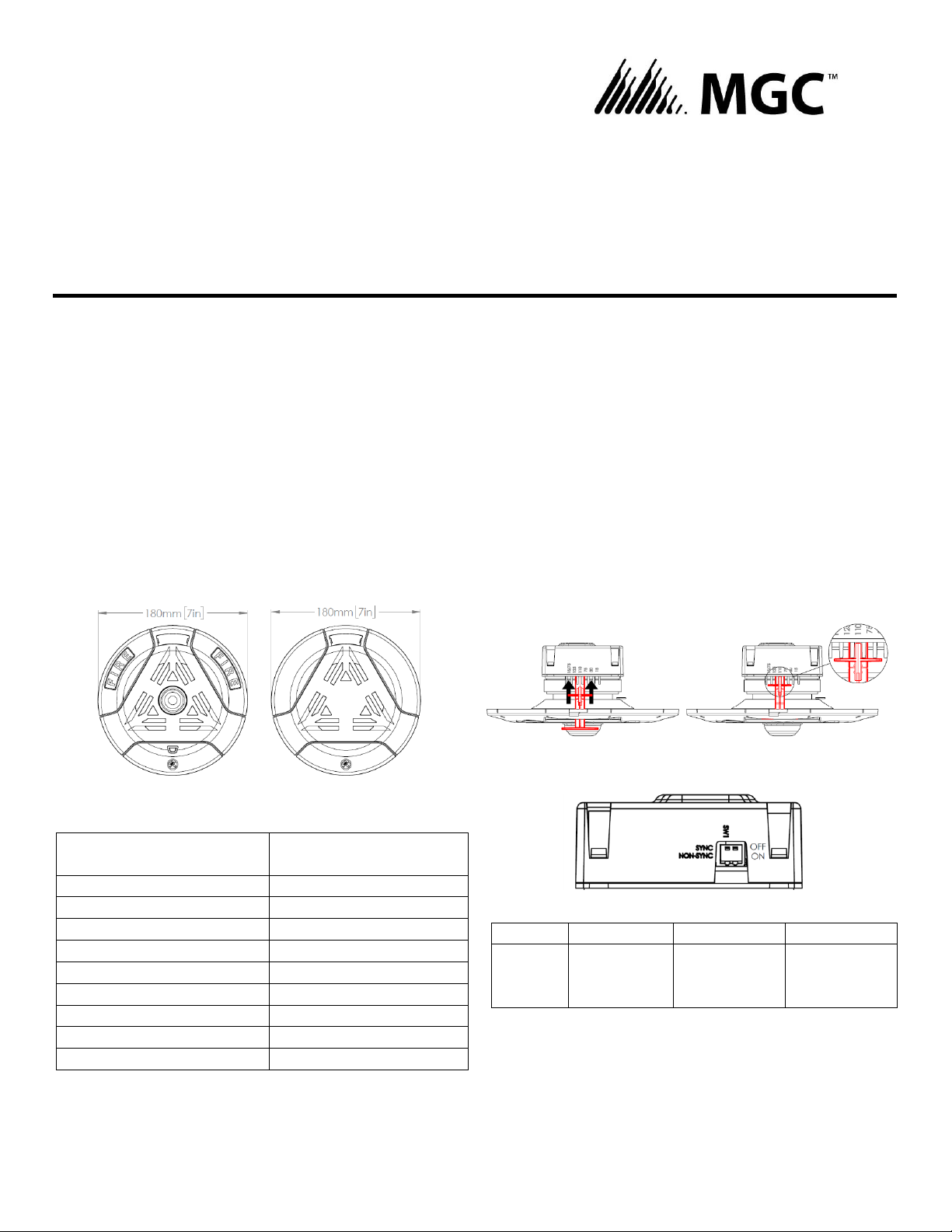
Figure 1 MODEL FRONT
SPPS-104 Series SPP-104 Series
Table 1 SPECIFICATION
Operating temperature
0⁰C to 49⁰C
(32⁰F to 122⁰F)
Humidity range
0% to 93%
Strobe flash rate
1 Hz (1 flash per sec.)
Nominal strobe voltage
Regulated 24VDC/VFWR*
Operating voltage range
16-33 VDC/VFWR
Nominal speaker voltage
25V or 70.7Vrms
Speaker Size
4”
Power Setting
¼, ½, 1, 2 W
Speaker Frequency range
400 -4000 Hz
Terminal wire gauge
12-22 AWG
*Note: For FWR signaling use a Mircom panel.
SETTING THE CANDELA (SPPS series only)
The candela can be set to 15, 30, 75, 110, 125, 15/75 for
SPPS-104-25 and SPPS-104-70 models.
The candela can be set to 50, 75, 90, 130, 185, 15/75 for
SPPS-104-25H and SPPS-104-70H models.
The factory default setting is 15 for SPPS-104-25/70
models, and 50 for SPPS-104-25H/70H models.
1. Pull out the candela selector from the device
2. Re-insert the selector tab into the notch that is labeled
with the desired candela setting (when removing or
inserting candela selector, ensure to do it straight).
Figure 2 INSERTING CANDELA SELECTOR
SETTING THE DIP SWITCHES
Figure 3 DIP SWITCH
Table 2 DIP SWTICH
DIP
OFF
ON
Switch 1
Input*
Synchronized
Regulated
24VDC/FWR
(Non-sync.)
*Note: Use “SYNC”when flash synchronization is required,
either through a sync module or built-in synchronization
on the control unit.
Use “NON-SYNC”when the appliances do not need to be
synchronized.
Note: DIP switch 1 default setting is OFF, synchronized.
Note: DIP switch 2 is not used.
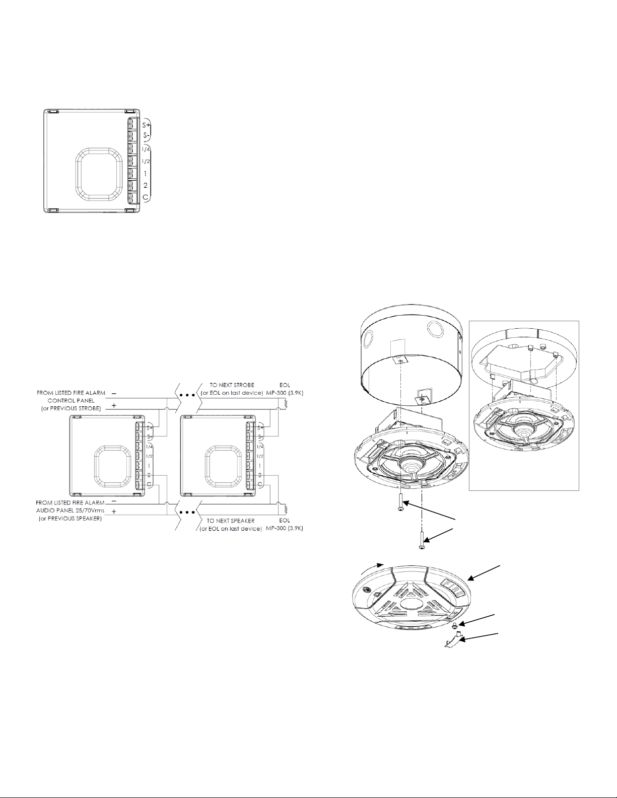
Step 1
WIRING
Figure 4 WIRING TAPS
FOR MODELS WITH STROBE FEATURE,
STROBE INPUT POWER (NAC)
SELECTABLE SPEAKER POWER (WATTS)
Note: Connect speaker between C and
desired wattage
Note: This device should be installed as per applicable
requirements of the authorities having jurisdiction.
Use the information in this document to determine the
total current draw of the devices. The total current draw of
the devices must not exceed the power supply of the
panel. In all cases, the installer should consider the voltage
drop to ensure that the last device on the circuit operates
within its rated voltage. For maximum strobe operating
current, please refer to Table 4.
Figure 5 DEVICE CONNECTION
Note: Wiring must be in accordance with CSA C22.1,
Canadian Electrical Code, Part I, Safety Standard for
Electrical Installations, Selection 32 and NFPA 70.
CAUTION
FOR SYSTEM SUPERVISION, FOR ALL TERMINAL TAPS, DO
NOT USE LOOPED WIRE UNDER TERMINALS. BREAK WIRE
RUN TO PROVIDE SUPERVISION OF CONNECTIONS.
ATTENTION
NE PAS UTILISER DE FILS EN BOUCLE SOUS LES BORNES.
POUR FOURNIR UN BON SUIVI DES CONNEXIONS.
INTERROMPRE LA CONTIUITÉ DES CÂBLES.
MOUNTING
MGC recommends spacing speaker strobe appliances in
compliance with CAN/ULC S524 and NFPA72.
(Optional. In case of using a standard 4” square 2 1/8 deep
electrical box, attach MP-184 adaptor ring from SPKC-W kit
to the unit using 4 snaps.)
1. Attach the unit to IB-104 electrical box with
two mounting screws.
2. Rotate the top cover clockwise to snap it in place.
3. Secure the top cover with securing screw and snap the
nameplate over the securing screw.
Figure 6 MOUTING DIAGRAM
Top cover
2 screws for attaching
device to IB-104
(Device with optional
adaptor ring)
Step 2
Securing screw
Nameplate

AUDIBLE RATINGS
Table 3 SOUND PRESSURE LEVEL OUTPUT
SPPS-104 SERIES
WATT Tap
UL Reverberant
(dBA@10ft)
ULC Anechoic
(dBA@3m)
70
25
70
25
2
89.0
89.0
87.8
88.2
1
86.7
86.8
85.1
85.6
1/2
84.0
83.9
82.3
82.6
1/4
80.8
80.7
78.9
79.5
SPP-104 SERIES
WATT Tap
UL Reverberant
(dBA@10ft)
ULC Anechoic
(dBA@3m)
70
25
70
25
2
89.2
89.2
89.6
89.4
1
86.5
87.4
86.8
86.8
1/2
83.7
84.5
83.9
83.7
1/4
80.5
81.2
80.7
80.5
Table 4 DIRECTIONAL SOUND CHARACTERISTICS
(Representative of both horizontal and vertical Axis)
SPPS-104 SERIES
ANGLE
dBA
+40°, -43°
-3
+76°, -74°
-6
±90°
-10.3
SPP-104 SERIES
ANGLE
±35°
-3
±72°
-6
±90°
-10.6
STROBE RATINGS
Table 5 STROBE OPERATING RMS CURRENTS (mA)
SPPS-104 SERIES
Candela
Regulated 24VDC
Regulated 24VFWR
15
33
33
30
47
43
75
111
100
110
204
186
125
295
277
15/75
112
100
SPPS-104 H SERIES
Candela
Regulated 24VDC
Regulated 24VFWR
50
54
57
75
78
83
90
100
104
130
159
162
185
343
327
15/75
82
87
Table 6 LIGHT DISPERSION
Degrees
% of Candela Rating
± 0
114
± 5
111
± 10
106
± 15
100
± 20
94
± 25
90
± 30
87
± 35
82
± 40
78
± 45
77
± 50
77
± 55
76
± 60
75
± 65
63
± 70
43
± 75
33
± 80
36
± 85
41
± 90
39
Compound ±45
78
Note. The following values are shown as percentages of
the rated light output at any candela setting.

Model Numbers
SPPS-104-25 Ceiling mounted speaker strobe 25V white
SPPS-104-70 Ceiling mounted speaker strobe 70V white
SPPS-104-25RCeiling mounted speaker strobe 25V red
SPPS-104-70RCeiling mounted speaker strobe 70V red
SPPS-104-25H Ceiling mounted speaker strobe 25V with High candela white
SPPS-104-70H Ceiling mounted speaker strobe 70V with High candela white
SPPS-104-25HRCeiling mounted speaker strobe 25V with High candela red
SPPS-104-70HRCeiling mounted speaker strobe 70V with High candela red
SPP-104-25 Ceiling mounted speaker 25V white
SPP-104-70 Ceiling mounted speaker 70V white
SPP-104-25RCeiling mounted speaker 25V red
SPP-104-70RCeiling mounted speaker 70V red
Accessories
SPKC-W Optional spacer
EOL-300 End of line resistor 3.9k Ohm
This manual suits for next models
14
Other MGC Speakers manuals


