MGF 120 Series User manual

mgf co.uk
UNDERSLUNG
LIFTING BEAM
CREATING SAFE WORKING ENVIRONMENTS
MODELS: 120 SERIES AND S80

With over 40 years of experience, MGF is a privately-owned company whose focus is the provision
of fully engineered excavation and structural support solutions and complimentary lifting and
safety equipment to the construction industry. We combine technical expertise and operational
performance to ensure the highest levels of customer service. With a focus on developing and
promoting industry best practice in excavation safety we aim to assist our customers in creating
safe working environments for their employees.
CUSTOMER SERVICE AND SUPPORT
The hire and sale of our products is fully supported by our team of qualified engineers,
experienced Technical Sales Representatives, hire desk and operational staff. Our hire centres
provide the focal point for service delivery where our hire desk team will be pleased to receive
your enquiry.
DELIVERY CAPABILITIES
Our dedicated fleet of vehicles offer a flexible solution to quickly meet our customers delivery
needs throughout the UK. We partner with several global shipping companies to ensure we can
quickly deliver our products on a global scale.
CREATING SAFE
WORKING ENVIRONMENTS

CONTENTS
SECTION 1: 120 SERIES UNDERSLUNG LIFTING BEAM
INTRODUCTION 4
SECTION 2: 120 SERIES UNDERSLUNG LIFTING BEAM
ASSEMBLY PROCEDURE 5
SECTION 3: S80 UNDERSLUNG LIFITNG BEAM INTRODUCTION 6
SECTION 4: S80 UNDERSLUNG LIFTING BEAM LOADING
OPTIONS 7
SECTION 5: S80 UNDERSLUNG LIFTING BEAM ASSEMBLY
PROCEDURE 9
SECTION 6: SAFE USE WARNINGS
PRE-LIFT CHECKS 10
ISSUE 1
MGF-GN36-r2-04/22-AW
MGF 120 Series Underslung Lifting Beams are available in two lengths of 3.5m and 4.25m,
each beam has a WLL of 2000kg making a pair capable of lifting 4000kg.
One of the intended applications for this product is handling static caravans. A pair of
beams achieve weight category D in accordance with NCC Code of Practice 501.
The 3.5m beam (product ID 2.9135) is suitable for 10ft wide caravans.
The 4.25m beam (product ID 2.9142) is suitable for 12ft wide caravans.
The system is provided as a rigid beam (A) with two 3.25t safety bow shackles (B).
It is recommended that the Underslung Lifting Beams are used in combination with either
MGF F55 Spreader Frames or S80 Spreader Beams above the caravan to prevent any
crushing effects.
PRODUCT
ID
HEIGHT WIDTH LENGTH WEIGHT
WLL* PER
LIFT POINT
WLL*
PER BEAM
SAFE LIFT
ZONE
NO LIFT
ZONE
(mm) (mm) (mm) (kg) (kg) (kg) (mm) (mm)
2.9135 200 132 3500 60 1,000 2,000 1260 980
2.9142 200 132 4250 70 1,000 2,000 1260 1730
*Working Load Limit
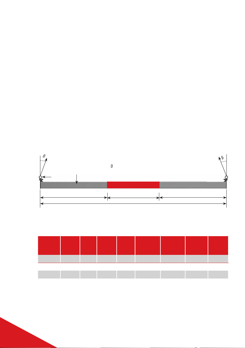
SPAN / CAPACITY CHART
UNDERSLUNG LIFTING BEAM TYPICAL SETUP
= Sling to vertical angle
B
A
SAFE LIFT ZONESAFE LIFT ZONE
SPAN
Figure 1: Typical beam setup
120 SERIES UNDERSLUNG
LIFTING BEAM
INTRODUCTION
NO LIFT ZONE
USER GUIDE SECTION 1
4
120 SERIES UNDERSLUNG LIFTING BEAM

120 SERIES UNDERSLUNG LIFTING BEAM - CARAVAN
HANDLING OVERVIEW
• Each beam has a WLL of 2,000kg
• 12ft caravans should be lifted with the 4.25m beams
• 10ft caravans should be lifted with the 3.50m beams
• Slings must be vertical [β] within 3° or less
• The designated caravan support points MUST be seated within the safe lift zone painted
yellow on the beam
• The caravan centre of gravity must be seated centrally on the beam to ensure a safe and
even lift, ensuring that lift points are not overloaded
• Prior to lifting, perform a test lift slightly above the ground to ensure that the load is
balanced
• Check the ID details on each component to ensure the correct lengths are used
• Connect suitable vertical slings (min. 1t WLL) to the lower shackles on either MGF
S80 Spreader Beams or F55 Spreader Frames, ensure lengths allow for clearance of
guttering etc.
• When using these beams with caravans position the Underslung Lifting Beams under
the caravan support points ensuring that they make contact within the ‘Safe Lift Zone’
• When using these lifting beams in other applications it is essential that the supports of
the item being lifted are within the ‘Safe Lift Zone’
• Connect the vertical slings to the 3.25t safety bow shackles [B] at each end of the lifting
beams
120 SERIES UNDERSLUNG
LIFTING BEAM ASSEMBLY
PROCEDURE
USER GUIDE SECTION 1 & 2
5
120 SERIES UNDERSLUNG LIFTING BEAM

S80 5m Spreader Extensions can be used as an underslung lifting beam in conjunction with
two end attachments in the configuration as shown below :
S80 UNDERSLUNG LIFTING
BEAM INTRODUCTION
PART REF DESCRIPTION PRODUCT ID WEIGHT/ITEM
(KG)
A85t Shackle 62
BDrop Link 2.9203 38
C55t Shackle 40
DEnd Attachment 2.9201 82
E5.0m Strut 2.9250 267
FTotal 16no. M20 x 65, grade 8.8 HT bolts, nuts and washers
Total Weight 711
A
B
C
DE
F
USER GUIDE SECTION 3
6
S80 UNDERSLUNG LIFTING BEAM
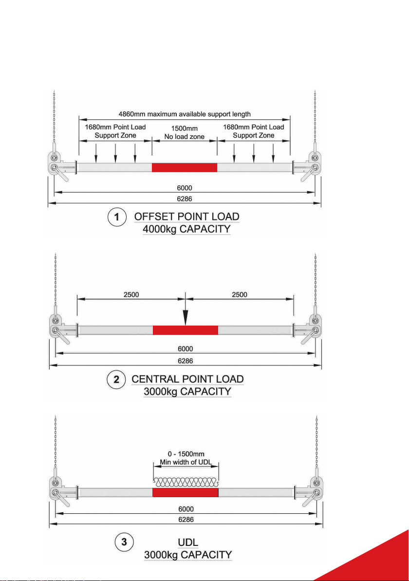
S80 UNDERSLUNG LIFTING
BEAM LOADING OPTIONS
USER GUIDE SECTION 4
7
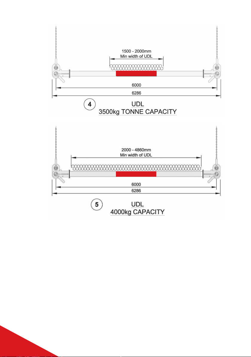
S80 UNDERSLUNG LIFTING BEAM
1. The beam has a WLL of 4,000kg when point loads are applied as long as the 1.5m
central span is not loaded.
2. The beam has a WLL of 3,000kg when point loads are concentrated to the 1.5m central
portion of the beam.
3. The beam has a WLL of 3,000kg when load is applied as a UDL (universally distributed
load) over a span from 0 to 1.50m.
4. The beam has a WLL of 3,500kg when load is applied as a UDL (universally distributed
load) over a span from 1.5m to 2.0m.
5. The beam has a WLL of 4,000kg when load is applied as a UDL (universally distributed
load) over a span from 2.0 to 4.86m.
USER GUIDE SECTION 4
8
S80 UNDERSLUNG LIFTING BEAM
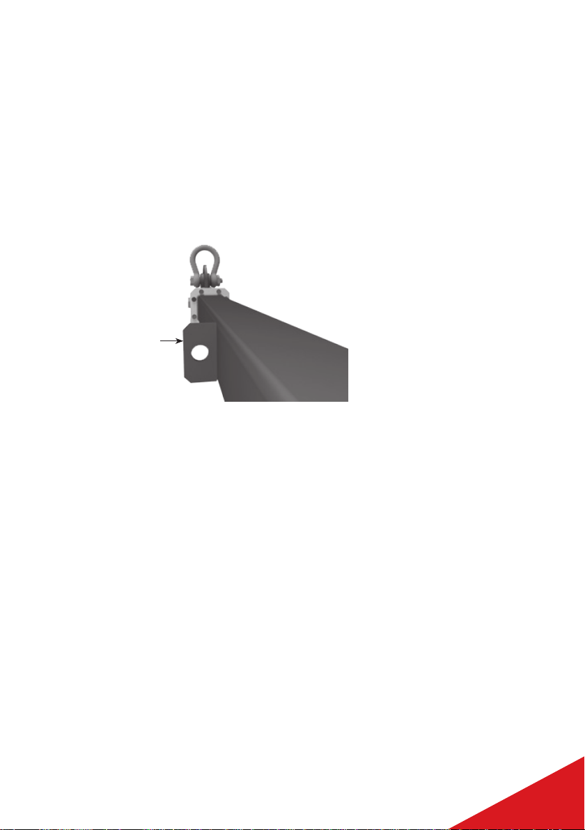
S80 UNDERSLUNG LIFTING
BEAM INTRODUCTION
• Check the ID details on each component to ensure the correct lengths are used
• Connect end attachments [D] to 5.0m S80 strut [E] with 8no. M20 x 65, grade 8.8 HT
bolts, nuts and washers [F] at each end. Tighten all bolts to a minimum torque of
240Nm, 2 threads minimum must be visible beyond the nut. Bolts should be re-
tightened before every lifting operation
• Ensure that the handling points [G] on the S80 strut point sidewards leaving a clear
space on the top face for positioning the load
G
• Connect drop link [B] to end attachment [D] with bow shackle [A]
• Connect suitable vertical slings (min. 2t WLL) to upper shackle [C] and secure onto
drop link [B]
• Ensure that there is adequate clearance between the load being lifted and the vertical
slings to avoid snagging
• It is recommended that S80 spreader beams or F55 spreader frames are used above to
support the underslung lifting beams below
• Vertical slings must be vertical [β] within 3° or less
• The load must be rigid and secured in such a way that the underslung lifting beams
cannot slide apart or together when in use
• The load must be seated in such a way that it cannot cause the S80 to rotate about its
axis
• The centre of gravity must be seated centrally on the beam to ensure a safe and even
lift, ensuring that lift points are not overloaded
• Prior to lifting, perform a test lift slightly above the ground to ensure that the load is
balanced
USER GUIDE SECTION 5
9
S80 UNDERSLUNG LIFTING BEAM

It is the hirer’s responsibility to inspect the beams and all fittings prior to any lifting
operations being undertaken. Consult an MGF representative before lifting if there is any
doubt over the quality of the equipment or if you are unsure about any aspect of these rules.
Equipment to be used in accordance with MGF’s terms and conditions of hire.
All operations must be carried out to approved method statements and risk assessments.
PRE-LIFT CHECKS
Before lifting there are several checks which should be done:
Must ensure that the slings are not twisted or tangled
Confirm that correct lifting points are being used
Keep the loaded beams clear of obstacles – any contact could cause unsafe
release of load or beam failure
Ensure that the sling lengths and rating are suitable, and the beam does not tilt
Ensure that the centre of gravity of the caravan is positioned centrally on the
beams to ensure an even lift
Each component needs to be checked prior to each lift
Prior to first use of a new assembly, carry out a trial lift just above ground level to
ensure that straightness is maintained under its own self-weight
Ensure that the lifting beams cannot slip on the support points during the lift.
Clamps may be required
SAFE USE WARNINGS
Before operatives use the equipment, they should read and understand
these warnings:
• Do not exceed stated WLL for all of the components
• Do not rig the vertical slings more than 3 degrees from vertical.
• When moving or positioning use tag lines to control movement.
• Individual components can be heavy and care must be taken if manual handling.
• The equipment must be used in accordance with the procedures from ‘Lifting
Operations and Lifting Equipment Regulations 1998’ (LOLER).
• Operatives using this system should be suitably trained, competent and have a
clear understanding of Safe Slinging procedures.
• Never lift over or near people, ensure an exclusion zone is in place during any
lifting operations.
• Do not use on uneven ground or during high winds.
• All loads being lifted should be rigid and additional safety measures may be
required to prevent the beams from moving or twisting during the lift.
USER GUIDE SECTION 6
10
UNDERSLUNG LIFTING BEAM
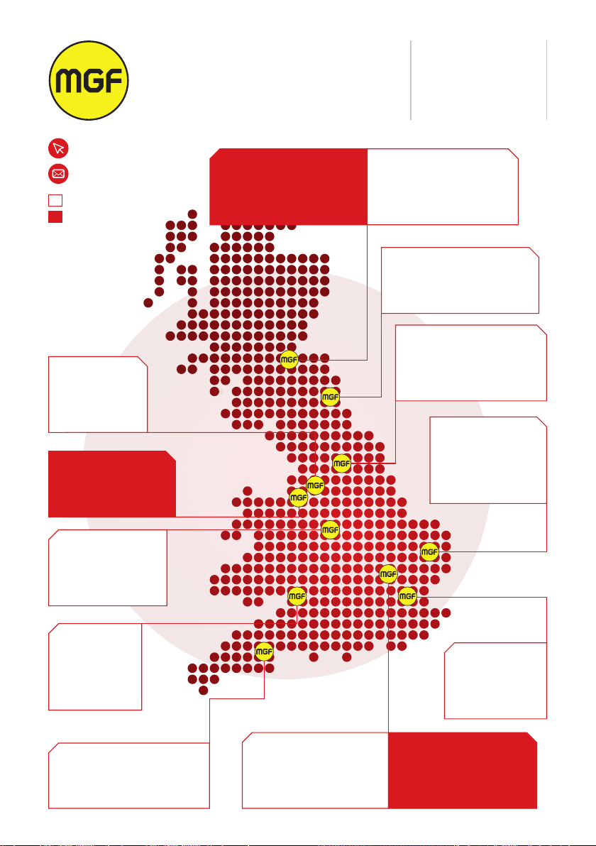
NORTH EAST – DURHAM DEPOT
Thistle Road, Littleburn Ind. Est.
Langley Moor, County Durham
DH7 8HJ
T: 01913 782100
YORKSHIRE –
CASTLEFORD DEPOT
Allerton Bywater Business Park
Newton Lane, Castleford
WF10 2AL
T: 01977 521930
EAST ANGLIA –
STANTON DEPOT
Unit 5, O’Brien Ind. Est.
Grove Lane, Stanton
Bury St. Edmunds
Suffolk, IP31 2AR
T: 01359 252204
LONDON –
DARTFORD DEPOT
Ray Lamb Way
Manor Road
Erith, Kent, DA8 2LB
T: 01322 344520
SOUTH WEST – EXETER DEPOT
Unit 58, Greendale Business Park
Woodbury Salterton, Exeter
EX5 1EW
T: 01395 233194
SOUTH WEST –
BRISTOL DEPOT
Severn Road
Chittening
Avonmouth
Bristol, BS11 0YL
T: 01179 820706
MIDLANDS –
RUGELEY DEPOT
Redbrook Lane
Brereton, Rugeley
Staffordshire, WS15 1QU
T: 01889 574777
NORTH WEST –
WARRINGTON DEPOT
Clayton Road, Birchwood
Warrington, WA3 6RP
T: 01925 598537
NORTH WEST –
ASTLEY DEPOT
Wallwork Road
Astley, Manchester
M29 7JT
T: 01942 896282
HEAD OFFICE
GRANT HOUSE
LOCKETT ROAD
ASHTON IN
MAKERFIELD
WIGAN, WN4 8DE
T: 01942 402700
ENGINEERING
CENTRE
FOUNDATION HOUSE
WALLWORK ROAD
ASTLEY, MANCHESTER
M29 7JT
T: 01942 402704
SOUTH EAST – TRING DEPOT
Units 21 & 22, Airfield Ind. Est.
Cheddington Lane
Long Marston, Tring
Hertfordshire, HP23 4QR
T: 01296 663250
SOUTH EAST – TRING DEPOT
Units 22a, Airfield Ind. Est.
Cheddington Lane
Long Marston, Tring
Hertfordshire, HP23 4QR
T: 01925 598537
WEST LOTHIAN –
LIVINGSTON DEPOT
Letham Road, Houstoun Ind. Est.
Livingston, West Lothian
EH54 5BY
T: 01506 535556
WEST LOTHIAN –
LIVINGSTON DEPOT
Letham Road, Houstoun Ind. Est.
Livingston, West Lothian
EH54 5BY
T: 01925 598537
mgf.co.uk
enquiries@mgf.co.uk
EXCAVATION SAFETY
STRUCTURAL
SUPPORT

enquiries@mgf.co.uk
Astley |Bristol |Castleford |Dartford |Durham |Exeter |Livingston |Rugeley |Stanton |Tring
Warrington |Wigan
MGF.CO.UK
This manual suits for next models
1
Table of contents
Other MGF Industrial Equipment manuals


