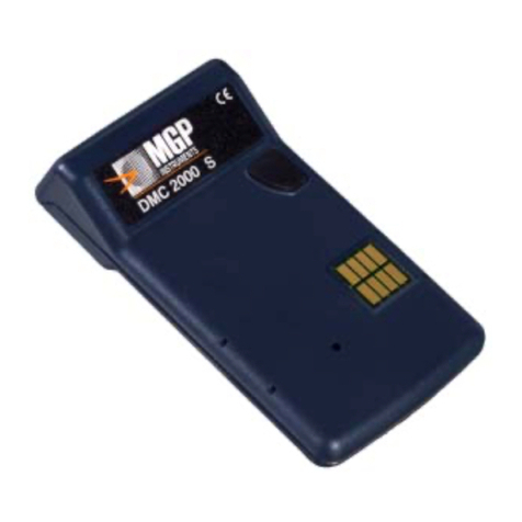
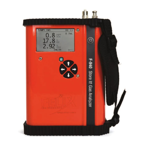
MGP DMC 2000 S User manual

Document # 15-00007
Revision 1
May 2001
DMC 2000S DMC 2000S
Electronic Dosimeter
User’s Manual

DMC 2000S Dosimeter
15-00007 Page 2 of 65
REVISION LOG: DMC 2000S Electronic Dosimeter User’s Manual
Revision #
Date
Revised
Pages
Comments
0
1
10/21/98
05/01/01
N/A
Page 20
Page 23
Page 35
Page 35
Page 54
All
All
Page 63
Original MGPI document # 15-00007,
based upon MGPSA document #
115170AA
Revised for new firmware version of
DMC 2000
Moved ‘SAT’ to the end of section
(5.3.2)
Moved ‘Dosimeter Serial’ number to the
beginning of section (5.3.2)
Added ‘Watch/Clock’ function to section
(6.4.2)
Added description and function of ‘EXT’
mode (exercise training) to section
(6.4.2)
Added ‘Calibration Mode’ in section
(10.1.4)
Added ‘Warning’ to pre-alarms
Changed all units in graphics and units to
reflect ‘mRem’ and mRem/h
Updated part numbers

DMC 2000S Dosimeter
15-00007 Page 3 of 65
TABLE OF CONTENTS
1. General 6
1.1 Document overview 6
1.2 Contents 6
1.3 Direct access to information 8
1.4 Conventions 8
1.5 Illustrations 8
2. Operating modes of the DMC 2000S dosimeter 9
2.1 Operating Mode 9
2.1.1. Autonomous mode 9
2.1.2. Satellite mode 9
2.2 Dosimeter function mode 9
2.2.1. Dosimeter storage mode 9
2.2.2. Pause mode 10
2.2.3. Measurement mode 10
2.2.4. Compatibility 10
3. Description 11
3.1 Front view 11
3.2 Back view 11
3.3 Display 12
The dosimeter’s top-mounted display allows viewing of measurements and alarms. 12
4. Start-up 13
4.1 Satellite mode 13
4.2 Autonomous mode 13
5. Operation in the satellite mode 14
5.1 Switching to measurement mode 14
5.2 Operation in the measurement mode 14
5.2.1. Displaying the dose equivalent measurement 14
5.2.2. Dose equivalent saturation 15
5.2.3. Displaying the dose rate measurement 15
5.2.4. Dose rate saturation 15
5.2.5. Fault and alarm indicators 16
5.2.6. Viewing alarm thresholds 16
Switching to pause mode 18
5.3 Operation in the pause mode 19
5.3.1. Normal display 19
5.3.2. Operation of the selector button 20
5.4 “Pass-by” reading 23
6. Operation in the autonomous mode 24
6.1 Switching to the measurement mode 24
6.2 Operation in the measurement mode 25
6.2.1. Displaying the dose equivalent measurement 25

DMC 2000S Dosimeter
15-00007 Page 4 of 65
6.2.2. Dose equivalent saturation 25
6.2.3. Displaying the dose rate measurement 26
6.2.4. Dose rate saturation 26
6.2.5. Fault and alarm indicators 27
6.2.6. Viewing alarm thresholds 27
6.3 Switching to pause mode 29
6.4 Operation in the pause mode 30
6.4.1. Normal display 30
6.4.2. Operation of the selector button 31
7. Alarms 37
7.1.1. Dose pre-alarm 37
7.1.2. Rate pre-alarm 38
7.1.3. Dose alarm 39
7.1.4. Dose rate alarm 39
7.1.5. Time alarm 40
8. Setting operating parameters 41
8.1 In the satellite mode 41
8.2 In the autonomous mode 41
8.3 Modifiable parameters 41
8.4 Modifying parameters 45
8.4.1. Accessing the modification mode 45
8.4.2. Procedures for modifying parameters 46
8.4.3. Example for setting parameters 47
9. Other functions 50
9.1 Emergency start-up 50
9.2 Historical 51
10. Faults 52
10.1.1. Battery low 52
10.1.2. “Defective” battery 53
10.1.3. Historical fault 53
10.1.4. Calibration fault 54
10.1.5. Detector fault 55
10.1.6. E2PROM fault 56
10.1.7. Initialization fault 56
10.1.8. Integrated circuit fault 56
11. Maintenance 57
11.1 Changing the battery 57
12. Technical characteristics 59
12.1 Physical characteristics 59
12.1.1. Isotropic graph 60
12.1.2. Linearity graph 60
12.2 Functional characteristics 61
12.3 Electrical characteristics 61
12.4 Mechanical characteristics 62
12.5 Environmental characteristics 62

DMC 2000S Dosimeter
15-00007 Page 6 of 65
1. General
1.1 Document overview
This document provides the information for using the DMC-2000S electronic dosimeter in two
operating modes:
• Part of a centralized dosimetry system
• Operation in the autonomous mode (i.e. as an individual or independent unit)
This document provides information about the dosimeter’s functions (alarms, display), normal
use (alarm acknowledgment) and first level maintenance (replacing the battery,
troubleshooting). For additional information relating to the functions listed below, refer to the
User’ s Manual for the centralized dosimeter system, such as MGPAC or DOSIVIEW.
! Assigning dosimeters
! Configuring dosimeters
! Pass-by readers
For some uses of the DMC 2000S (dosimetry system and teledosimetry applications) additional
equipment is required (MGPAC, LDM, WRM...). For further information, refer to the
corresponding equipment’s User’s Manual.
1.2 Contents
This document contains information regarding:
!Operating modes of the DMC 2000S
This section briefly describes the dosimeter’s operating modes and function modes.
!A description of the DMC 2000S
This section describes the dosimeter from the user’s point of view (selector button, display...).
!Start-up of the DMC 2000S
This section describes the start-up procedures for the dosimeter.
!Operation of the DMC 2000S in the satellite mode
This section details the normal conditions of use for the DMC 2000S as part of a
dosimetry system.
!Operation of the DMC 2000S in autonomous mode

DMC 2000S Dosimeter
15-00007 Page 7 of 65
This section describes the use of a DMC 2000S in a “stand-alone” mode, independent of
any peripheral reader.
!The alarming functions of the DMC 2000S
This section describes the different operating modes of the audible and visual alarms.
!Setting the operating parameters of the DMC 2000S
This section lists the main operating parameters of the DMC 2000S dosimeter, as well as
the procedures to modify them.
!Additional functions of the DMC 2000S
This section describes the “emergency start-up” and “historical” functions.
!Fault analysis of the DMC 2000S
This section lists possible faults as well as providing a troubleshooting guide.
This section does not describe procedures to follow in the event of an alarm. Those
procedures are detailed in the alarm section.
!Simple, first level maintenance of the DMC 2000S
This section describes how to troubleshoot the dosimeter.
!The technical characteristics of the DMC 2000S
This section describes the dosimeter’s physical, electrical and mechanical characteristics,
and the environmental conditions of use.
!An appendix on teledosimetry, alarm transmission, and external probe connector
This appendix describes the input / output functions of the connector.
!A glossary of terms

DMC 2000S Dosimeter
15-00007 Page 8 of 65
1.3 Direct access to information
! This document provides basic information which may be needed to operate the DMC
2000S dosimeter. To assist the user in understanding the dosimeter’s operation, a glossary
of terms has been provided at the end of the document that describes acronyms,
abbreviations and terminology typically associated with the DMC 2000S.
1.4 Conventions
Use of typographical symbols:
Symbols “ !” and “ #”:
These symbols are used for descriptions and lists.
The symbol “ !” corresponds to the first level of a list.
The symbol “ #” corresponds to the second level of a list.
For legibility reasons, these symbols are aligned vertically.
1.5 Illustrations
On the illustrations of the display:
! shaded areas indicate that the information flashes
! the indicator light as shown below is flashing
! the “functional indicators” are always flashing unless otherwise specified
DMC 2000S dosimeter display
Note: the illustration above contains more data than the actual display for illustrative purposes.
“Functional
indicators“
(a
l
ways
fl
as
hin
g)
Shaded area (flashing)
Indicator light
(flashing)

DMC 2000S Dosimeter
15-00007 Page 9 of 65
2. Operating modes of the DMC 2000S dosimeter
The main operating modes and function modes of the DMC 2000S dosimeter are
described below.
2.1Operating Mode
The DMC 2000S can be used in two different operating modes: the “autonomous”
mode and the “satellite” mode.
The mode selection is normally set at the factory. However, it can be selected by using
the DOSIMASS software and an LDM 2000 reader.
Note: Please refer to the DOSIMASS User’s Manual for instructions.
2.1.1. Autonomous mode
This mode allows the DMC 2000S to operate individually or independently, without any
other equipment.
2.1.2. Satellite mode
This mode allows the DMC 2000S to be used as a part of a dosimetry system, which
includes other equipment and software (LDM 2000, MGPAC, Sentinel etc.).
2.2 Dosimeter function mode
Regardless of its operating mode (“autonomous” or “satellite”), the DMC 2000S
dosimeter is always in one of the following functional modes:
! dosimeter storage
! pause
! measurement
2.2.1. Dosimeter storage mode
When in this mode, the DMC 2000S dosimeter is not operational and its power
consumption is at a minimum level.
Switching to this mode requires the use of a centralized dosimetry system.

DMC 2000S Dosimeter
15-00007 Page 10 of 65
2.2.2. Pause mode
When in this mode, the DMC 2000S:
! periodically monitors:
# status of the battery
# proper operation of the detector
# integrity of calibration data and initialization parameters
# management of the internally stored HISTOGRAM
# permanently displays the message “PAUSE,” a personalized message or messages
indicating any faults that have been detected
In this mode the “pass-by data exchange” function is operational.
Note: the personalized message displayed in the pause mode can be set using the
DOSIMASS software.
2.2.3. Measurement mode
When in this mode, the DMC 2000S dosimeter continuously:
! performs measurements
# of the Hp (10) dose equivalent
# of the current dose rate
# of the time spent in area
! displays the dose, alarms and messages relating to detected faults
! manages the alarms and pre-alarms
! manages the internally stored HISTOGRAM
! signals audibly, under alarm conditions
! periodically monitors:
# the battery status
# the detector’s operational status
# the integrity of the initialization and calibration data
In this mode, the “pass-by data exchange” function is operational.
2.2.4. Compatibility
All functions of the DMC-90 and the DMC-100 dosimeters are available with the
DMC 2000S, in particular, use with previous dosimeter readers (LDM-91, LDM-101,
LDM-201) and dosimeter calibrators, CDM 21 and IRD 2000, equipped with new
software. The user’s (display) area of message 22 has been reduced from 14 to 12 bits.
Those sites using their own access control software may need to make modifications to
the program in order to integrate the DMC 2000S into their system. Please contact MGPI
for more information.

DMC 2000S Dosimeter
15-00007 Page 11 of 65
3. Description
3.1 Front view
3.2 Back view
indicator light
display
selector button
ISO connector for
the CTM 2000,
MUX 2000, AM
16, DDC 16 and
PEA 20000
pocket clip
battery cover
speaker
detector location

DMC 2000S Dosimeter
15-00007 Page 12 of 65
3.3 Display
The dosimeter’s top-mounted display allows viewing of measurements and alarms.
In the example shown below the display indicates a dose alarm (i.e.
the alarm threshold programmed into the dosimeter for the dose
equivalent has been exceeded):
! the indicator light flashes
! the “ Dose Alarm ” indicator flashes
! the value of the dose is displayed (9.5 mRem)
! note that displayed units can be configured for mSv
indicator ligh
t
display area

DMC 2000S Dosimeter
15-00007 Page 13 of 65
4. Start-up
To start up a DMC 2000S dosimeter, the following procedures must be performed:
! it must be initialized (i.e. switched from storage mode to pause mode)
! it must be configured (i.e. programmed for alarm threshold values, dose rate display
authorization, alarm rate authorization, alarm duration, etc.)
! if in satellite mode, it must be assigned to an individual
! it must be activated (i.e. turned on for normal operation)
4.1Satellite mode
In a centralized dosimetry system, a “server” computer performs the start-up procedure via an
LDM 2000 reader.
4.2Autonomous mode
For use in the autonomous mode, the initialization and initial configuration are generally
performed at the factory.
Use of the selector button activates the dosimeter (refer to the section on Setting operating
parameters In the autonomous mode, page 41).
In addition, modification of some parameters can also be performed when in the pause mode
by using the selector button (refer to the section on Setting operating parameters In the
autonomous mode, page 41).

DMC 2000S Dosimeter
15-00007 Page 14 of 65
5. Operation in the satellite mode
5.1 Switching to measurement mode
Switching to the measurement mode implies activating the DMC 2000S dosimeter to measure
the wearer’s dose equivalent.
In a centralized dosimetry system, switching to the measurement mode is accomplished when
passing by an LDM 2000 access control reader.
When switching to the measurement mode, the display reads as shown below:
! the functional indicators flash
! the dose value is continuously displayed (in the appropriate units, as selected during
dosimeter configuration)
5.2 Operation in the measurement mode
5.2.1. Displaying the dose equivalent measurement
When in the measurement mode, the DMC 2000S dosimeter continuously measures the
Hp(10) dose equivalent, as well as performing other operations (see section Measurement
mode, page 10).
The display shows the dose value. The unit, format (fixed or floating point) and display
resolution are selected during dosimeter configuration.
Example:
Note: when used in a centralized dosimetry system, the dose display can be intentionally
blanked. In this case, only the “functional indicators” and faults are displayed.

DMC 2000S Dosimeter
15-00007 Page 15 of 65
5.2.2. Dose equivalent saturation
When the dose equivalent exceeds the value 999.9 Rem
(9999.99 mSv), the display reads as shown below. This indicates
that the dosimeter has become saturated and must be reset by the
appropriate reader / software.
5.2.3. Displaying the dose rate measurement
Pressing and immediately releasing the selector button displays the
dose rate value for 30 seconds. The unit, format (fixed or floating
point) and display resolution are selected during dosimeter
configuration.
After 30 seconds, the dose equivalent value is displayed once again:
Note: other display combinations of dose/rate are available. Please
contact MGPI for further details.
5.2.4. Dose rate saturation
When the dose rate exceeds the value 999.9 rem/h (9999 mSv/h),
the display reads as shown below. This indicates that the dosimeter
has become saturated and must be reset by the appropriate reader /
software.

DMC 2000S Dosimeter
15-00007 Page 16 of 65
5.2.5. Fault and alarm indicators
In the event of a fault or an alarm, additional messages alternate on
the display every 2 seconds (see the example of an alarm below):
If authorized, the alarm can be acknowledged by pressing the
selector button.
Note:
!The alarm messages are described later in Section 7, beginning
on page 36.
!Dosimeter fault messages are described in Section 10, beginning
on page 51, which includes a troubleshooting guide.
5.2.6. Viewing alarm thresholds
Settings for the alarm and pre-alarm thresholds can be viewed in the measurement mode
by holding the selector button.
To display the thresholds, press and hold the selector button continuously for at least 10
seconds, without releasing. The various thresholds are displayed in succession (every 2
seconds).
When the selector button is released, the current dose equivalent is automatically
displayed on the dosimeter.
The threshold display sequence is as follows:
5.2.6.1. Dose alarm threshold display
This value corresponds to the alarm threshold of the dose equivalent
for the main measurement.
The display is shown in scientific notation.
In the example above, the value of the rate corresponds to 5.92
mRem (5.92 * 100mRem)

DMC 2000S Dosimeter
15-00007 Page 17 of 65
5.2.6.2. Rate alarm threshold display
This value corresponds to the alarm threshold of the dose rate for the
main measurement.
The display is shown in scientific notation.
In the example above, the value of the rate corresponds to 0.990
mRem/h (9.90 * 10-1 mRem/h)
5.2.6.3. Time alarm threshold display
This value corresponds to the length of time alarm threshold (shown
here: 94 hours).
5.2.6.4. Dose pre-alarm warning threshold display
This value corresponds to the pre-alarm threshold of the dose
equivalent for the main measurement (shown here: 1 mRem).
5.2.6.5. Rate pre-alarm warning threshold display
This value corresponds to the pre-alarm threshold of the dose
equivalent rate for the main measurement (shown here: 0.130
mRem/h).

DMC 2000S Dosimeter
15-00007 Page 18 of 65
Switching to pause mode
Switching to the pause mode implies deactivating the DMC 2000S dosimeter. In other words,
suppressing the dose measurement functions.
In a centralized dosimetry system, switching to the pause mode is accomplished when passing
by an LDM 2000 access control monitor.
When switched to the pause mode, the display reads as shown below:
! the functional indicators flash
! one of the following messages can be displayed (depending on the dosimeter configuration:
assigned or non-assigned...)
# non-assigned dosimeter:
# assigned dosimeter:
or name of the wearer, depending on the dosimeter configuration

DMC 2000S Dosimeter
15-00007 Page 19 of 65
5.3 Operation in the pause mode
5.3.1. Normal display
When the DMC 2000S dosimeter is in the pause mode, it continuously performs the
operations described on page 10.
The display shows the message “ PAUSE ” or “ affect ” (or wearer’s name) is
depending on whether or not it is assigned.
# non-assigned dosimeter:
# assigned dosimeter:
In the event of a fault, additional, alternating messages are displayed
every 2 seconds (see the example below):
Note: all dosimeter fault messages are described in Section 10,
beginning on page 51, which includes a troubleshooting guide.

DMC 2000S Dosimeter
15-00007 Page 20 of 65
5.3.2. Operation of the selector button
Using the selector button in the satellite mode allows additional information to be
viewed on the DMC 2000S dosimeter’s display. This data and the corresponding
displays are described below. Depending on the dosimeter’s configuration, some data
can be intentionally concealed.
The different functions of the selector button are listed below:
! pressing the button:
# displays the next data set
! pressing and holding:
# maintains the current data on the display
! after 5 seconds without pressing:
# reverts to normal display in the pause mode
The following data is displayed in succession (by pressing the selector button):
5.3.2.1. Dosimeter number display
This value corresponds to the identification number specific to the
dosimeter.
5.3.2.2. Cumulative dose display
This data corresponds to the cumulative dose equivalent for the main
measurement during the last time period in the measurement mode
(i.e. since the last dose reset to zero, normally performed upon area
entry, depending on the centralized dosimetry system’s
configuration).
The display is shown in scientific notation.
In the example above, the value of the rate corresponds to 5.70
mRem (5.70 * 100mRem).
Other manuals for DMC 2000 S
1
Table of contents
Other MGP Measuring Instrument manuals

