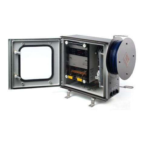
ParTech 8100 User manual

INSTRUCTION MANUAL
8100 & 8200 Monitor
Version 3

** This page is intentiona y eft b ank **

8100/8200 Monitor Instruction Manua
Table of Contents
1 Introduction...................................................................................................................................................................4
1.1 Manua Conventions..........................................................................................................................................4
1.2 Product Description............................................................................................................................................4
1.3 App ications........................................................................................................................................................5
2 Insta ation.....................................................................................................................................................................6
2.1 Location.............................................................................................................................................................6
2.2 Mounting Options...............................................................................................................................................6
3 E ectrica Connections...................................................................................................................................................7
3.1 Supp y Vo tage...................................................................................................................................................7
4 Configuration.................................................................................................................................................................8
4.1 Setpoint..............................................................................................................................................................8
4.2 De ay..................................................................................................................................................................8
5 S udge B anket Leve Detection....................................................................................................................................9
5.1 Description.........................................................................................................................................................9
5.2 Sensor Insta ation.............................................................................................................................................9
5.3 Monitor Configuration.........................................................................................................................................9
6 Maintenance...............................................................................................................................................................11
6.1 Inspection.........................................................................................................................................................11
6.2 Fau t Finding....................................................................................................................................................11
7 Technica Support.......................................................................................................................................................12
7.1 Returning Instruments for Repair.....................................................................................................................12
8 Technica Specification 8100/8200 Monitor.................................................................................................................13
168270IM-02 Issue Date 05/01/2010 Page 3 of 14

8100/8200 Monitor Instruction Manua
1 Introduction
1.1 Manual Conventions
This manua covers the 8100 & 8200 Version 3 Monitors
The manua describes the configuration and operation of the 8100/ 8200 Monitor and inc udes information regarding
sensors. A dimensions stated in this manua are in mi imetres un ess otherwise stated.
The manua has been written on the basis that the user has a basic know edge of instrumentation and an
understanding of the type of measurements being made. Whi st every attempt has been made to ensure that the
instructions are correct, common sense and good engineering practice shou d a ways be used to adapt to specific site
requirements. Training in the use of the 8100/ 8200 Monitor can be provided by Partech, p ease contact sa es for
further information.
1.2 Product Description
The 8100 Monitor is a sing e channe instrument for use with one sensor. It provides a sing e a arm re ay output and a
sing e fau t re ay output. The a arm set point and de ay are configured using contro s mounted on the front pane . The
status of the input channe is indicated by three LED’s.
The 8200 Monitor has two input channe s for use with two sensors. It provides two a arm re ay outputs (one for each
channe ) and a sing e fau t re ay output. The fau t re ay is used to indicate a fau t on either input channe . The 8200
Monitor has two pairs of set point and de ay contro s and two sets of status LED’s. The a arm set point and de ay for
each channe can be independent y set and the status of each channe is indicated separate y.
The 8100/ 8200 Monitor has an IP65 rated enc osure and is suitab e for outdoor use, however, a protective cover or
outer enc osure is recommended to further protect the instrument from harsh environmenta conditions.
1.2.1 Options
Part Number Description
163600 8100 Monitor Version 3 (115/230VAC)
171370 8100/8200 Monitor 12VDC Supp y Option
171360 8100/8200 Monitor 24VDC Supp y Option
1.2.2 Compatible Sensors
The 8100/ 8200 monitor can be used with the fo owing Partech sensors:
IR Series IR8, IR15, IR40, IR100
ST Series 0 –1500mg/ , 0 – 10000mg/ , 0 – 30000mg/
1.2.3 Fault Indication
Fau t indication is via the i umination of a status LED that is c ear y visib e on the front pane of the monitor. When
there is a fau t present the orange FAULT LED i uminates.
1.2. Alarm Activation
When the sensor is c ear and not in a fau t condition then the green OK LED is i uminated. If however, the sensor is
obscured or b ocked then the re ay wi enter into the a arm condition and the red ALARM LED wi become i uminated.
1.2.5 Delay Operation
A de ay can be introduced between conditions for an a arm turning on being met and the re ay changing state. At any
time during a de ay, if the conditions for turning the a arm on are removed, then the de ay wi end and the a arm re ay
wi not change state. The de ay can be set between 1 & 90 seconds. The de ay function is in p ace to try to avoid the
occurrence of fa se a arms that may be caused by suspended debris.
168270IM-02 Issue Date 05/01/2010 Page 4 of 14

8100/8200 Monitor Instruction Manua
1.2.6 Alarm Relays
The a arm re ays are interna y configured for fai safe operation. When power is app ied and the sensors are c ear the
re ays wi be energised, on a arm the re ays are de-energised. Each a arm has norma y c osed and norma y open
contacts for externa signa ing, the norma condition is when the unit is powered and the a arm is off.
1.2.7 Fault Relay
The fau t re ay is uti ised when there is a prob em with the sensor or a ternative y there may have been a power fai ure
to the system and in this instance the re ay wi be de-energised and therefore send the monitor into a fau t state
1.3 Applications
The 8100 & 8200 Monitors, when combined with a compatib e sensor, are designed for use as a s udge b anket eve
detector, a s udge density switch, or as a suspended so ids/turbidity switch. The 8100 & 8200 Monitors are therefore
suitab e for interfacing with automatic de-s udging contro of primary and secondary sett ement tanks, thickener contro
and high and ow b anket eve a arm, or as a simp e a arm in a water/ waste water f ow.
1.3.1 Sludge Blanket Level Detection
When used for this operation the monitor uses an IR or ST series sensor, which is suspended by its cab e to the
desired monitoring depth in the tank. When the sett ed s udge reaches the sensor then the a arm output is activated.
This can then be used as an input to a process system to direct y contro pumps, be mouths or simp y to a ert the
operator. The same princip e can be used to monitor when the s udge reaches a minimum point when it is being
removed from the ho ding tank.
1.3.2 Suspended Solids Switch
The 8100/8200 Monitor can be used as a suspended so ids switch when used in conjunction with the IR and ST series
sensors. The sensor can be insta ed in an eff uent channe to detect a va ue of suspended so ids and give a high
a arm.
168270IM-02 Issue Date 05/01/2010 Page 5 of 14

8100/8200 Monitor Instruction Manua
2 Installation
2.1 Location
The 8100/8200 Monitor is housed in an IP65 enc osure and is therefore suitab e for fie d mounting. It is advisab e to
mount the monitor in a ocation that has some protection from the environment; this cou d be a GRP/meta cabinet, in
a centra room or the use of a protective shie d. Suitab e enc osures can be provided by Partech.
2.2 Mounting Options
A range of mounting options are avai ab e for the 8100/8200 Monitors, which wi a ow the user to insta the sensor in
a wide variety of ocations.
The 8100/8200 Monitor is designed so that it can be surface mounted, the ho e positions required for this are shown
be ow.
Mounting hardware such as handrai brackets, protective hoods and sensor brackets are avai ab e from Partech. The
8200 Monitor using the standard bracket (Part Number 171280) is shown above.
When mounting the sensor and monitor it is recommended that the two entities be kept as c ose together as possib e
so that the ca ibration process is simp ified. The sensors are supp ied with a standard ength of 10 metres of cab e,
though this can be increased on request to a maximum of 100 metres. The cab e can be extended using a junction
box and good qua ity instrument cab e (3-core minimum).
168270IM-02 Issue Date 05/01/2010 Page 6 of 14
75.50 75.50
5.00
5.00 DIA
6.00
120.00

8100/8200 Monitor Instruction Manua
3 Electrical Connections
WARNING: DISCONNECT THE MAINS SUPPLY BEFORE REMOVING THE TERMINAL COVER
Removing the termina compartment cover, which is ocated at the base of the front pane , gives access to the
8100/8200 Monitor e ectrica connections. Before removing the termina cover make sure that the e ectrica supp y to
the instrument is disconnected.
When the instrument is insta ed, it is essentia to check that the supp y vo tage se ector switch position is correct for
the intended supp y vo tage. If this is not checked the instrument cou d be damaged. The vo tage se ector is shown
be ow
COM
LIVE
NEUTRAL
N/C
N/O
COM
N/C
N/O
COM
N/C
EARTH
ALARM 2
ALARM 1
INPUT
12V
INPUT
0V
12V
12V
N/O
GND
N/O
0V
2
Fuse
Vo tage Se ector
Connection Termina s
FAULT CLEAN O/P SENSOR 1 SENSOR 2
The e ectrica supp y to the unit shou d be insta ed such that there is a means of iso ating the supp y to the unit and
the supp y is protected with a fuse or trip. The instrument has a supp y fuse fitted interna y.
The 8100 monitor is supp ied with three PG11 cab e g ands fitted and has provision for a further PG11 g and, whereas
the 8200 comes with four fitted cab e g ands. If any fitted cab e g ands are not being used then the g ands must be
sea ed to prevent the ingress of moisture into the unit.
Shown be ow are the termina connections for the 8100/8200 Monitor.
COM
LIVE
NEUTRAL
N/C
N/O
COM
N/C
N/O
COM
N/C
EARTH
ALARM 2ALARM 1
SENSOR I/P
12V
SENSOR I/P
0V
12V
12V
N/O
GND
N/O
0V
POWER FAULT SENSOR 1
CLEAN O/P
SENSOR 2
Sensor Type
Termina s IR Series Sensor ST Series Sensor
Sensor I/P White White
Sensor 12V Red Red
Sensor 0V B ack/ B ue B ack/ B ue
3.1 Supply Voltage
The supp y vo tage for the 8100/8200 Monitor is avai ab e in 115/230VAC (switchab e), 12VDC or 24VDC versions.
The vo tage can be se ected between either 115VAC or 230VAC by switching the se ector switch, ocated behind the
front cover. To gain access to the vo tage se ector remove the four b ack screws from the b ue front pane . The vo tage
se ector switch is then visib e in the bottom eft corner, ocated a ongside the fuse.
168270IM-02 Issue Date 05/01/2010 Page 7 of 14

8100/8200 Monitor Instruction Manua
Configuration
CHANNEL 1
SE TPOINT
8200
OK
FAULT
ALAR M
DELAY
OK
ALAR M
FAULT
CHANNEL 2
SE TPOINT
DELAY
Setpoint De ay Contro s and status indicators are situated on the front pane of the 8100/8200 Monitor (front pane of
8200 monitor shown above). To access the adjustment dia s then the outer cover must be opened. The front pane has
a setpoint and a de ay adjustment contro and a so on the front pane are the three status indicators:
OK – Green LED
ALARM – Red LED
FAULT – Orange LED
.1 Setpoint
The type of sensor used determines the measurement/detection range of the system. It is however possib e to do
some fie d adjustment and fine tuning of the system once insta ed.
By turning the setpoint contro from fu y anti-c ockwise to fu y c ockwise it is possib e to a ter the setpoint from 5 - 95%
of the range of the sensor.
.2 Delay
The de ay contro is used to a ter the ength of time after an a arm condition occurs that the a arm re ay is activated.
Once an a arm condition ends, the de ay wi a so determine how ong the a arm re ay remains in the a arm condition
before deactivating. The de ay can be set between 1 and 90 seconds and is used to prevent fa se a arms being
indicated. For examp e when the sensor signa momentari y goes above the a arm va ue due to unrepresentative
debris.
To increase the ength of de ay the contro marked DELAY on the front pane of the 8100/8200 Monitor shou d be
turned c ockwise. When turned fu y c ockwise the de ay is set at 90 seconds.
168270IM-02 Issue Date 05/01/2010 Page 8 of 14

8100/8200 Monitor Instruction Manua
5 Sludge Blanket Level Detection
5.1 Description
The typica s udge b anket eve detection insta ation is in a sett ement tank. The system is made up of a sing e or dua
sensor configuration and a monitor. There wi a so be associated mounting hardware, which is dependent upon the
app ications requirements.
The monitor is typica y mounted on a handrai on the bridge of a sett ement tank. The sensor is suspended by its
cab e; though it shou d be noted that the sensor must be fastened to the fixing point provided by the mounting bracket
and is not eft to hang from the cab e g and at the base of the monitor.
When mounting the monitor and sensor on a sett ement tank with rotating bridge, the sensor shou d norma y be
ocated on the eading edge, approximate y ha f way between the centre and outside edge of the tank, as shown
above. Care shou d be taken when mounting the sensor to ensure that it does not trai into the scraper.
5.2 Sensor Installation
Once the bracket/monitor has been attached to the handrai via the sadd e c amps and U-bo ts and the sensor has
been connected to the monitor, it is then a matter of passing the cab e through the various retaining c amps and
owering it into the sett ement tank to the desired depth at which the s udge b anket is required to be detected. When
assessing mounting options, attention shou d be paid to the accessibi ity of the sensor for ca ibration and
maintenance, stabi ity of the sensor in the f ow conditions present on site and it must a so be ensured that when
mounting the sensor it is fu y submerged at a times.
The sensor can be suspended by its cab e, but the top end of the cab e must be fastened to a fixed point. It shou d be
noted that the sensor must not be a owed to hang direct from the cab e g and at the bottom of the monitor.
5.3 Monitor Configuration
When supp ied the factory mid-point settings may not be suitab e for the required app ication. If this is the case then
the fo owing procedures shou d be undertaken
5.3.1 Blanket not detected
If the sensor is not detecting the s udge b anket and the green OK ight remains on when the sensor is in the b anket,
take the fo owing action:
•With the sensor in the s udge b anket, the setpoint contro shou d be turned anti-c ockwise s ow y unti the red
ALARM LED i uminates. This indicates that the sensor has detected the s udge b anket.
168270IM-02 Issue Date 05/01/2010 Page 9 of 14
Sett ement
Tank
SLUDGE SLUDGE
SUPERNATENT
SUPERNATENT
8100 Monitor with
A arm LED Activated
Sett ement
Tank
SLUDGE SLUDGE
SUPERNATENT
8200 Monitor
SUPERNATENT

8100/8200 Monitor Instruction Manua
5.3.2 Blanket continually detected
If the sensor is continua y detecting the s udge interface and the red ALARM LED stays on when the sensor is above
the s udge b anket the fo owing action shou d be taken:
•With the sensor above the s udge b anket, set the de ay to the minimum, then the a arm point contro shou d be
s ow y turned c ockwise unti the green OK LED i uminates. This indicates that the sensor is correct y, not
detecting the s udge b anket.
Note: If the setpoint contro is turned fu y c ockwise and the detector continua y indicates the presence of the s udge
b anket when the sensor is above the b anket, the sensor that is fitted is too sensitive and an a ternative sensor wi
have to be fitted
For accurate adjustment of the setpoint to a required eve :
1. Immerse the sensor fu y in a known samp e of the required va ue.
2. Turn the a arm point contro fu y anti-c ockwise; the green OK LED shou d i uminate.
3. The a arm point contro shou d be turned c ockwise unti the red ALARM LED i uminates.
The desired a arm point has now been set and the contro er wi now detect s udge b ankets of this va ue or higher.
Note: In the event of the sensor being changed, it wi be necessary to repeat the above a arm point adjustment in
order to obtain accurate resu ts
168270IM-02 Issue Date 05/01/2010 Page 10 of 14

8100/8200 Monitor Instruction Manua
6 Maintenance
To maximise the operationa ife of the monitor and sensor, regu ar inspection is recommended. The frequency of this
is dependent on the specific operation of each site, however an initia week y inspection to observe the characteristics
of the app ication is recommended, ong term operationa practice can be decided from these inspections.
The manua c ean system requires the physica remova of the sensor from the app ication for the c eaning of the
enses to be carried out.
It is advisab e that at regu ar interva s the sensor is removed from the app ication and both the enses and the sensor
body are c eaned a ong with the mounting brackets.
6.1 Inspection
It is envisaged that an inspection of the monitor and sensor wi inc ude the fo owing:
•Check security of brackets
•Remova of the sensor from the app ication.
•Checking for damage to cab es.
•C eaning of the sensor using a suitab e detergent and remova of a ragging.
•Inspection of the g ass enses for staining, scouring, cracks or chips.
•Checking for moisture/signs of eakage inside the sensor and monitor.
6.2 Fault Finding
The fo owing can cause a fa se a arm or fau t signa :
•Materia (rag, weed, etc) caught on the sensor and affecting the measuring system - remove sensor, manua y
c ean and re-insta .
•Turbu ence (caused by high f ow, aeration etc) in the so ution being measured – position the sensor so
turbu ence has as minima effect as possib e on the sensor.
•Bad connection of the sensor cab e - check a connections are secure y fastened
168270IM-02 Issue Date 05/01/2010 Page 11 of 14

8100/8200 Monitor Instruction Manua
7 Technical Support
Technica Support is avai ab e by phone, fax, or e-mai , the detai s of which are shown be ow.
Phone: +44 (0) 1726 879800
Fax: +44 (0) 1726 879801
website: www.partech.co.uk/
To enab e us to provide quick and accurate technica support p ease have the fo owing information ready when you
contact our Customer Support Manager:
•Monitor type, seria number, and software version number.
•Sensor type, and seria number.
•App ication detai s.
•Description of fau t.
7.1 Returning Instruments for Repair
If equipment needs to be returned to Partech for repair or service the fo owing address shou d be used:
SERVICE DEPT.
PARTECH (ELECTRONICS) LTD
CHARLESTOWN
ST AUSTELL
CORNWALL
PL25 3NN
UNITED KINGDOM
P ease inc ude the fo owing information with the returned equipment. A so ensure that sensors are adequate y
protected for transportation (Advice on packing can be provided by our service department).
•Contact name and phone number.
•Return address for equipment.
•Description of fau t or service required.
•Any specia safety precautions because of nature of app ication.
168270IM-02 Issue Date 05/01/2010 Page 12 of 14

8100/8200 Monitor Instruction Manua
8 Technical Specification 8100/8200 Monitor
8.1.1 General
Operation Voltage: .........................115/230 VAC 50/60Hz +10%/-15% (Voltage Sele tor))
Nominal 12VDC..............................9 – 18Vd
Nominal 24VDC..............................18 – 36Vd
Power Consumption........................8VA
Supply Fuse....................................100mA Anti surge 20mm x 5mm (fitted internally)
Operating Temperature Range.......0 to 50
°
C
Storage Temperature Range..........-20 to +60
°
C
8.1.2 Alarm Outputs
Number of Outputs..........................8100 - 1 alarm ,1 fault
........................................................8200 – 2 alarms, 1 fault
Alarm Type......................................SPCO
Operation........................................Fail Safe (De-energised in alarm ondition)
Relay Rating....................................5A @ 230Va , 5A @ 30Vd
8.1.3 Enclosure
En losure Materiall..........................ABS
Cable Glands..................................PG11
Terminals........................................Max ondu tor ross se tion 2.5 mm2
Environmental Rating......................IP65
Weight.............................................1 Kg
Dimensions.....................................160 x 195 x 105 mm (h x w x d)
8.1. EMC
EMC................................................EN 50081-1 (1992), EN 50082-1 (1994)
168270IM-02 Issue Date 05/01/2010 Page 13 of 14

This manual suits for next models
1
Table of contents
Other ParTech Measuring Instrument manuals