Mhouse GA1 Product manual
GA1
oscillating arm
Installation instructions and warnings
Istruzioni ed avvertenze per l’installazione
Instructions et avertissements pour l’installation
Anweisungen und Hinweise für die Installation
Instrucciones y advertencias para la instalación
Installatievoorschriften en waarschuwingen
IST GA1 4865 Rev.00

Description and intended purpose
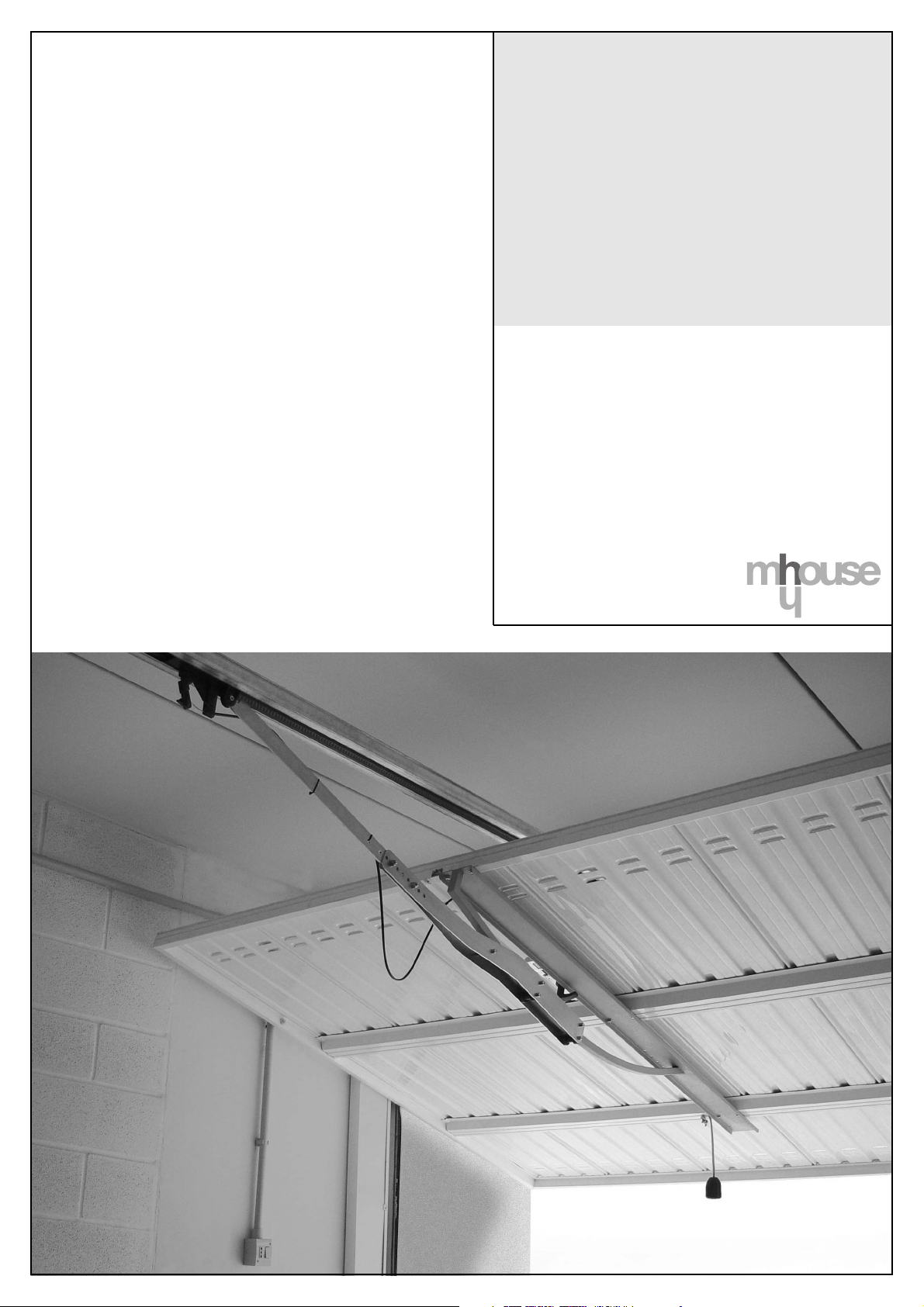
The GA1 oscillating arm is an indispensable
accessory for the automation of counterweight-
or spring-balanced overhead doors.
GA1 can be mounted at the centre of the door
or just to the side of the opening handle, as
shown in Fig. 1.
Preliminary verification
Make sure that the value specified in Fig. 2, i.e.
the minimum distance between the gearmotor
guide and the uppermost point reached by the
upper edge of the door in its travel, is at least
65 mm. Otherwise GA1 cannot be installed.
Installation
1. Mount the upper support [A] on the bow [B],
and secure its lower part to the bottom bar
[C] as shown in Fig. 3.
2. Fasten the bottom bar to the door [D] with
screws; make sure you also fasten the upper
support of the bow [A] as shown in Fig. 4.
3. Pay attention to the installation direction, the
bow must be located at the top as shown in
Fig. 5.
4. Complete the installation of the sliding part of
GA1 by assembling the parts as shown in
Fig. 6.
5. Remove the bent arm supplied with the car-
riage on the gearmotor guide [E] and install
in its place the straight arm [F] of GA1, as
shown in Fig. 7
6. Close the door, then fasten the straight arm
[F] to GA1, as shown in Fig. 8.
Supply
Table 1: list of small parts for GA1
1 Screw V8x40 no.1
2 Nut D8 no.3
3 Screw V6x30 no.1
4 Nut D6 no.6
5 Screw V8x25 no.2
6 Screw V6x55 no.5
GB Descrizione e destinazione d’uso
Il braccio oscillante GA1 è un accessorio neces-
sario quando il portone da automatizzare è di tipo
basculante, sia a contrappesi che a molle.
GA1 può essere montato al centro del portone o
leggermente a lato della maniglia di apertura,
come indicato in Fig.1.
Verifica preliminare
Verificare che la quota di Figura 2, cioè la distan-
za minima tra la guida del motoriduttore ed il pun-
to massimo raggiunto nella corsa del bordo
superiore del portone, abbia un valore minimo di
65 mm. Altrimenti GD1 non può essere installato.
Installazione
1. Montare sull’archetto [B] il supporto superiore
[A] e fissarlo nella parte inferiore alla barra di
fondo [C] come indicato in Fig. 3
2. Fissare la barra di fondo al portone nei punti
[D] per mezzo di viti avendo cura di compren-
dere anche il supporto superiore dell’archetto
[A] come indicato in Fig.4
3. Porre attenzione al verso di installazione, l’ar-
chetto deve essere posto verso l’alto come
indicato in Fig. 5
4. Completare l’installazione della parte scorrevo-
le di GA1 assemblando i pezzi come in indica-
to Fig. 6
5. Togliere il braccio curvo in dotazione al carrello
sulla guida del motoriduttore [E] ed installare,
al suo posto, il braccio dritto [F] di GA1, come
indicato in Fig. 7
6. Chiudere il portone, quindi fissare il braccio
dritto [F] a GA1, come indicato in Fig. 8.
Dotazione
Tabella 1: elenco minuteria per GA1
1 Vite V8X40 n° 1
2 Dado D8 n° 3
3 Vite V6x30 n° 1
4 Dado D6 n° 6
5 Vite V6X55 n° 5
6 Vite V8X25 n° 2
Description et application
Le bras oscillant GA1 est un accessoire néces-
saire quand la porte à automatiser est bascu-
lante, du type à contrepoids ou à ressorts.
GA1 peut être monté au centre de la porte ou
légèrement désaxé par rapport à la poignée
d’ouverture comme l’indique la Fig. 1.
Contrôle préliminaire
Vérifier que la mesure indiquée dans la Figure
2, c’est-à-dire la distance minimum entre le rail
de l’opérateur et le point maximum atteint dans
la course par le bord supérieur de la porte, soit
d’au moins 65 mm. En cas contraire GA1 ne
peut pas être installé.
Installation
1. Monter la patte supérieure [A] sur la barre
courbe [B] et fixer cette dernière à la barre
de support [C] dans la partie inférieure, com-
me l’indique la Fig. 3.
2. Fixer la barre de support à la porte au niveau
des points [D] à l’aide des vis, en veillant à
bloquer ensemble la patte supérieure [A] de
la barre courbe, comme l’indique le détail de
la fig. 4.
3. Faire attention au sens d’installation, la barre
courbe doit être montée dans la partie haute
de la barre de support comme l’indique la
Fig. 5.
4.
Compléter l’installation de la partie coulissante
de GA1 en assemblant les pièces comme l’in-
dique la Fig. 6.
5. Enlever le bras courbe qui équipe le chariot
sur le rail de l’opérateur [E] et installer à sa
place le bras droit [F] de GA1, comme l’in-
dique la Fig. 7.
6. Fermer la porte puis fixer le bras droit [F] à
GA1 comme l’indique la Fig. 8.
Fourniture
Tableau 1: liste des pièces pour GA1
1 Vis V8x40 1
2 Écrou D8 3
3 Vis V6x30 1
4 Écrou D6 6
5 Vis V6x55 5
6 Vis V8x25 2
I F

Beschreibung und Einsatz
Bei dem Schwenkarm GA1 handelt es sich um
ein Zubehör, das notwendig ist, wenn das zu
automatisierende Tor ein Schwingtor mit
Gegengewichten oder Federn ist.
GA1 kann in die Tormitte oder gleich neben
den Öffnungsgriff montiert werden, wie auf
Abb. 1 angegeben.
Vorprüfungen
Prüfen, ob das Maß in Abbildung 2 bzw. der
Mindestabstand zwischen Führung des Toröff-
ners und Höchstpunkt, den die obere Torkan-
te beim Lauf erreicht, mindestens 65 mm
beträgt, andernfalls kann GD1 nicht installiert
werden.
Installation
1. Am Bogen [B] die obere Halterung [A]
befestigen und diese wie auf Abb. 3 gezeigt
am unteren Teil der Schiene [C] befestigen.
2. Die Schiene an den Punkten [D] anschrau-
ben, dabei auch die obere Halterung des
Bogens [A] einschließen, wie auf Abb. 4
gezeigt.
3. Die Installationsrichtung beachten: der
Bogen muss nach oben gerichtet sein, wie
auf Abb. 5 gezeigt.
4. Die Installation des Schiebesystems von
GA1 vervollständigen, indem die Teile wie
auf Abb. 6 montiert werden.
5. Den mit dem Wagen gelieferten gebogenen
Arm an der Führung des Toröffners [E] ent-
fernen und an seiner Stelle den geraden Arm
[F] von GA1 montieren, wie auf Abb. 7
gezeigt.
6. Das Tor schließen, dann den geraden Arm
[F] an GA1 befestigen, wie auf Abb. 8
gezeigt.
Ausstattung
Tabelle 1: Verzeichnis der Kleinwaren für GA1
1 Schraube V8X40 Nr. 1
2 Mutter D8 Nr. 3
3 Schraube V6x30 Nr. 1
4 Mutter D6 Nr. 6
5 Schraube V6X55 Nr. 5
6 Schraube V8X25 Nr. 2
Descripción y uso previsto
El brazo oscilante GA1 es un accesorio necesa-
rio cuando el portón que se tiene que automati-
zar es basculante, tanto cuando es con contra-
pesos como cuando es con muelles.
GA1 puede montarse en el centro del portón o
ligeramente desplazado al lado del tirador de
apertura como muestra la Fig.1.
Verificación preliminar
Verifique que la cuota de la Fig. 2, es decir la dis-
tancia mínima entre la guía del motorreductor y
el punto máximo que alcanza el borde superior
del portón en el movimiento, tenga un valor míni-
mo de 65 mm. En caso contrario GD1 no puede
instalarse.
Instalación
1. Monte el soporte superior [A] en el arco [B] y
luego sujételo por la parte inferior a la barra de
fondo [C] tal como muestra la Fig. 3.
2. Sujete la barra de fondo al portón en los pun-
tos [D] mediante tornillos incluyendo también
el soporte superior del arco [A] tal como
muestra la Fig.4.
3. Cuidado con el sentido de la instalación, el
arco tiene que estar situado en la parte supe-
rior tal como muestra la Fig. 5.
4. Complete la instalación de la parte corredera
de GA1 uniendo las piezas tal como muestra
la Fig. 6.
5. Desmonte el brazo curvo premontado en el
carro sobre la guía del motorreductor [E] e
instale en su lugar el brazo recto [F] de GA1,
tal como indica la Fig. 7.
6. Cierre el portón y luego sujete el brazo recto
[F] a GA1 tal como indica la Fig. 8.
Equipado con:
Tabla 1: lista componentes para GA1
1 Tornillo V8X40 n.° 1
2 Tuerca D8 n.° 3
3 Tornillo V6x30 n.° 1
4 Tuerca D6 n.° 6
5 Tornillo V6X55 n.° 5
6 Tornillo V8X25 n.° 2
Beschrijving en gebruiksbestemming
De kantelarm GA1 is een accessoire dat u
nodig hebt, wanneer de te automatiseren deur
een kanteldeur is, of deze nu tegengewichten
of veren heeft.
GA1 kan zowel in het midden van de deur
gemonteerd worden als ook iets naast de ope-
ningsgreep, zoals dat op afb.1 te zien is.
Controle vooraf
Vergewis u ervan dat de waarde op afbeelding
2, dat wil zeggen de minimumafstand tussen
de rail van de deuropener en het hoogste punt
dat de deur bereikt, wanneer deze geopend
wordt, tenminste 65 mm bedraagt. Anders kan
GA1 niet geïnstalleerd worden.
Installatie
1. Monteer de bovenste steun [A] op de boog
[B] en zet deze onderaan op de geleidings-
balk [C] vast zoals op afb. 3 afgebeeld is.
2. Bevestig de geleidingsbalk met schroeven
op de punten [D] op de deur waarbij u
ervoor dient te zorgen dat ook de boven-
steun van de boog [A] daarin zit, zoals dat
op afb.4 te zien is
3.
Let bij de installatie goed op de richting, de
boog moet bovenaan komen zoals u dat op
afb. 5 kunt zien.
4. Completeer de installatie van het beweeg-
bare deel van GA1 door de verschillende
onderdelen daarvan te assembleren zoals
dat op afb. 6 te zien is.
5. Verwijder de gebogen arm [E] die met de
wagen op de rail van de deuropener meege-
leverd is en monteer op de plaats daarvan
de rechte arm [E] van GA1, zoals dat op
afb. 7 te zien is.
6. Doe de deur dicht en bevestig vervolgens de
rechte arm [F] op GA1, zoals op afb. 8 aan-
gegeven is.
Meegeleverd wordt:
tabel 1: lijst verbruiksmateriaal voor GA1
1 Schroef V8X40 nr.1
2 Moer D8 nr.3
3 Schroef V6x30 nr.1
4 Moer D6 nr.6
5 Schroef V6X55 nr.5
6 Schroef V8X25 nr.2
D E NL

Mhouse srl
Via Pezza Alta 13
31046 Oderzo TV Italia
Tel. +39 0422 202 109
Fax +39 0422 852 582
www.mhouse.biz
Fig. 1
Fig. 3 Fig. 4 Fig. 5
Fig. 2
A
65÷300 mm
1
4
2
3
Fig. 6 Fig. 8
Fig. 7
4
A
D
5
5
F
F
E
6
6
2
2
B
C
4
4
5
Other Mhouse Door Opening System manuals

Popular Door Opening System manuals by other brands


Besam
Besam Swingmaster MP Installation, adjustment and maintenance instructions

Assa Abloy
Assa Abloy SARGENT 1431 Series instructions

GAL
GAL MOVFR Quick setup

Häfele
Häfele Finetta T 70 VF manual

AGS
AGS D-PL Instructions for fitting, operating and maintenance

Stanley
Stanley MA900ñ Installation and owner's manual

WITTUR
WITTUR Hydra Plus UD300 Instruction handbook

Alutech
Alutech TR-3019-230E-ICU Assembly and operation manual

Pamex
Pamex KT-INP35 Installation instruction

MPC
MPC ATD ACTUATOR 50 ATD-313186 Operating and OPERATING AND INSTALLATION Manual

Chamberlain
Chamberlain T user guide

Dorma
Dorma MUTO COMFORT M DORMOTION 50 Mounting instruction