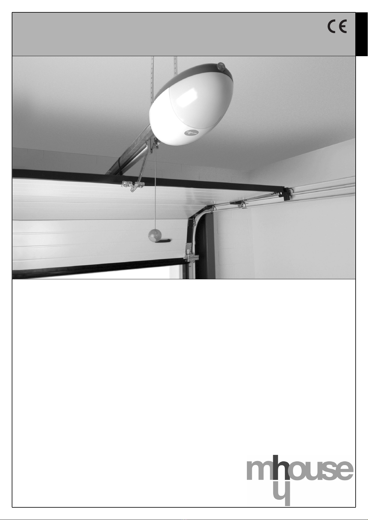
Mhouse GD0 Product manual
Installation instructions and warnings
English
IST GD0-GB 4865 Rev. 00 del 15-03-2005
MhouseKit GD0
For the automation of a sectional or overhead door.

2 Instructions GD0
Information
1 Warnings 3
2 Product description 4
2.1 Applications 4
2.2 Description of the automation 4
2.3 Description of devices 5
2.3.1 GD0K Electromechanical Gearmotor 5
2.3.2 PH0 photocells (optional) 6
2.3.3 KS1 key-operated selector switch (optional) 6
2.3.4 FL1 flashing light with incorporated aerial (optional) 6
2.3.5 TX4 radio transmitter 6
3 Installation 7
3.1 Preliminary checks 7
3.1.1 Operating limits 8
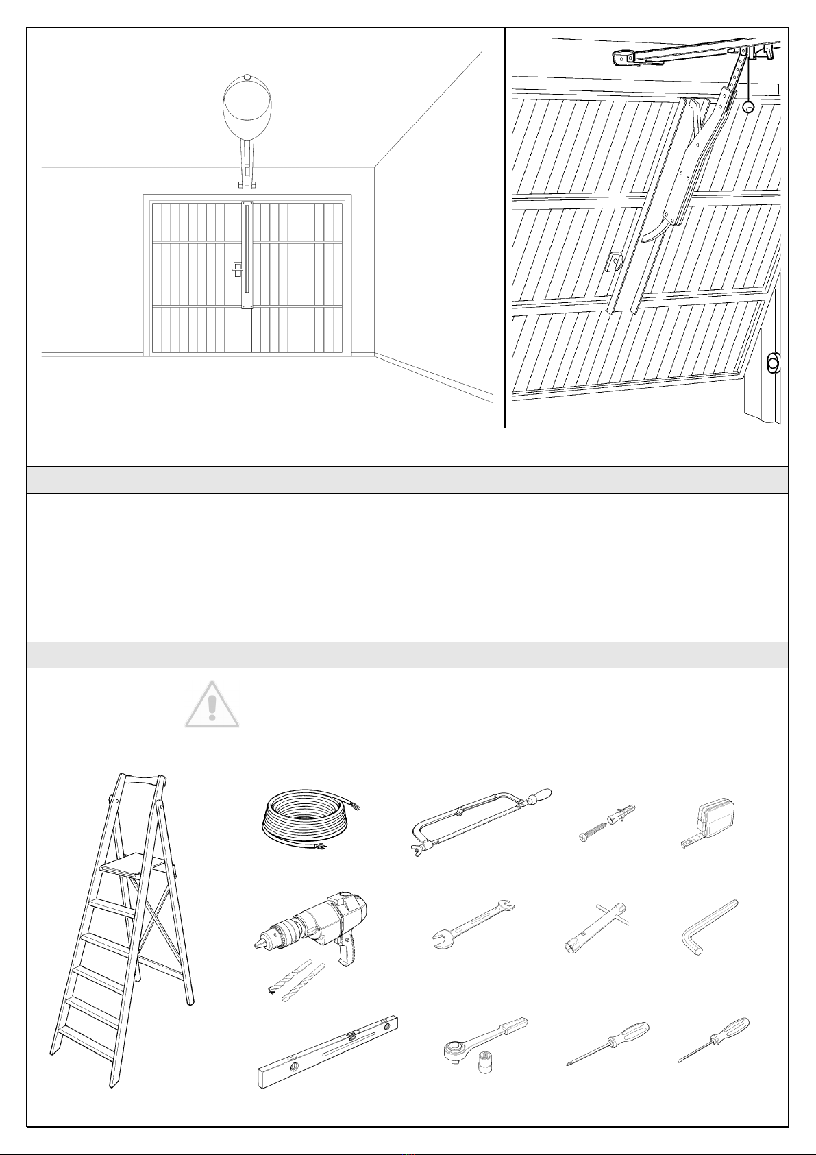
3.1.2 Tools and Materials 8
3.1.3 List of cables 9
3.2 Preparing the Electrical System 9
3.2.1 Connection to the Electrical Mains 9
3.3 Installation of the Various Devices 10
3.3.1 Guide assembly 10
3.3.2 Fixing of the gearmotor to the guide 11
3.3.3 Fixing of the gearmotor to the ceiling 11
3.3.4 PH0 Photocells (optional) 13
3.3.5 KS1 key-operated selector switch (optional) 13
3.3.6 FL1 flashing light (optional) 14
3.3.7 Electrical connections to the GD0K control unit 15
3.4 Power Supply Connection 16
3.5 Initial checks 16
3.5.1 Recognition of the door’s open and closed positions 17
3.5.2 Testing the radio transmitter 17
3.6 Regulations 17
3.6.1 Selecting door speed 17
3.6.2 Selecting the type of operating cycle 18
3.7 Testing and Commissioning 18
3.7.1 Testing 18
3.7.2 Commissioning 19
4 Maintenance 19
4.1 Dismantling and Disposal 19
5 Additional Information 20
5.1 Advanced Adjustments 20
5.1.1 Adjusting the Parameters with the Radio Transmitter 20
5.1.2 Checking the Adjustments with the Radio Transmitter 20
5.2 Optional Accessories 21
5.3 Adding or Removing Devices 21
5.3.1 Phototest output 21
5.3.2 STOP Input 21
5.4 Memorization of Radio Transmitters 22
5.4.1 Memorization Mode 1 22
5.4.2 Memorization Mode 2 22
5.4.3 Remote memorization 22
5.4.4 Deleting a Radio Transmitter 23
5.4.5 Deleting all the Radio Transmitters 23
5.5 Troubleshooting 23
5.6 Diagnostics and Signals 24
5.6.1 Photocells 24
5.6.2 Flashing and courtesy lights 24
5.6.3 Control Unit 25
6 Technical characteristics 26
7 Annexes 28
7.1 Annexe 1: CE Declaration of Conformity of GD0 Components 29
7.2 Annexe 2: CE Declaration of Conformity of Power Operated
Sectional or Overhead Door 31
7.3 Annexe 3. Operating guide 33
7.3.1 Safety regulations 33
7.3.2 Door Control 33
7.3.3 Maintenance Operations to Be Performed by the User 34
7.3.4 Replacing the Remote Control Battery 34
7.3.5 Lamp replacement 34
Contents
This manual may be reproduced provided no part of it is omitted or
modified. No part of this manual may be translated into other languages
without the prior authorization and subsequent examination by
MHOUSE.
MHOUSE disclaims all responsibility for damage resulting from improper
use of its products. You are therefore invited to read this manual carefully.
MHOUSE, in order to improve its products, reserves the right to modify
them at any time without prior notice. In any case, the manufacturer
guarantees their functionality and fitness for the intended purposes.
For any information please contact:
MHOUSE S.r.l.
via Pezza Alta, 13, ZI 31046 Oderzo
Tel: 0422 202109
Fax: 0422 852582
email: [email protected]
http: www.mhouse.biz
Instructions GD0 3
1 Warnings
Important installer and user safety instructions
• If this is the first time that you install a GD0 sectional or overhead door
automation system we recommend that you dedicate some of your time
to reading this manual. You should read it before you start installing the
system, so you don’t have to rush to finish the work.
Keep all the components of the GD0 system handy so that you can read,
check and verify all the information contained in this manual. However,
do not carry out the adjustment and memorization stages otherwise,
during the actual installation of the products, you will have to deal with
settings that differ from the original factory ones.
• When reading this manual, pay special attention to the sections marked
by the following symbol:
these sections are particularly important for safety.
• Store this manual safely for future use.
• This manual, as well as the design and manufacture of the devices that
make up GD0, comply fully with the standards and regulations in force.
• Considering the hazards that may exist during the installation and oper-
ation of GD0, it is necessary that also the installation be carried out in
strict compliance with current legislation, standards and regulations, par-
ticularly:
• This manual contains important information regarding personal
safety; before you start installing the components, it is important
that you read and understand all the information contained here-
in. Do not proceed with the installation if you have doubts of any
sort; if necessary, refer to the MHOUSE customer service depart-
ment for clarifications.
• Follow all installation instructions
• Before you start with the installation, make sure that each sin-
gle GD0 device is suitable for the intended automation purposes;
pay special attention to the data provided in chapter 6 “Technical
Characteristics”. If even a single device is not suitable for the
intended application, do not proceed with the installation.
• Before you start with the installation, check whether additional
devices or materials are needed to complete the automation with
GD0 based on the specific application requirements.
• The GD0 automation system must not be installed outdoors
• The GD0 automation system must not be used until the automa-
tion has been commissioned as described in paragraph 3.7.2
“Commissioning”.
• The GD0 automation system cannot be considered as a suitable
intrusion protection system. If you require efficient protection you
need to integrate GD0 with other devices.
• The packing materials for GD0 must be disposed of in compli-
ance with local regulations.
• Do not make modifications to any components unless provided
for in this manual. This type of operations will only cause mal-
functions. MHOUSE disclaims any liability for damage resulting
from modified products.
• Components must never be immersed in water or other liquids.
Also during installation, do not allow liquids to enter the gearmo-
tor or other open devices.
• In the event that liquid substances have penetrated inside the
automation devices, immediately disconnect the power supply
and contact the MHOUSE customer service department. The use
of GD0 in these conditions can be dangerous.
•Keep all components of GD0 away from heat sources and open
flames; these could damage the components and cause malfunc-
tions, fire or dangerous situations.
• Connect the gearmotor only to a power supply line equipped
with safety grounding system.
• All operations requiring the opening of the protection shell of
GD0 device must be performed with the gearmotor disconnected
from the power supply; if the disconnection device is not identifi-
able, post the following sign on it: “WARNING: MAINTENANCE
WORK IN PROGRESS”.
• In the event that any automatic switches or fuses are tripped,
you must identify the failure and eliminate it before you reset
them.
• If a failure occurs that cannot be solved using the information
provided in this manual, refer to the MHOUSE customer service
department.
Particular warnings concerning the suitable use of this product in relation
to the 98/37CE “Machine Directive” (ex 89/392/EEC):
• This product comes onto the market as a “machine component” and
is therefore manufactured to be integrated to a machine or assembled
with other machines in order to create “a machine”, under the directive
98/37/EC, only in combination with other components and in the man-
ner described in the present instructions manual. As specified in the
directive 98/37CE the use of this product is not admitted until the man-
ufacturer of the machine on which this product is mounted has identified
and declared it as conforming to the directive 98/37/CE.
Particular warnings concerning the suitable use of this product in relation
to the 73/23/EEC “Low Voltage” Directive and subsequent modification
93/68/EEC:
• This product responds to the provisions foreseen by the “Low Voltage”
Directive if used in the configurations foreseen in this instructions manu-
al and in combination with the articles present in the Mhouse S.r.l. prod-
uct catalogue. If the product is not used in configurations or is used with
other products that have not been foreseen, the requirements may not
be guaranteed; the use of the product is prohibited in these situations
until the correspondence to the requirements foreseen by the directive
have been verified by those performing the installation.
Particular warnings concerning the suitable use of this product in relation
to the 89/336/EEC “Electromagnetic Compatibility” Directive and subse-
quent modifications 92/31/EEC and 93/68/EEC:
• This product has been subjected to tests regarding the electromag-
netic compatibility in the most critical of use conditions, in the configura-
tions foreseen in this instructions manual and in combination with articles
present in the Mhouse S.r.l. product catalogue. The electromagnetic
compatibility may not be guaranteed if used in configurations or with oth-
er products that have not been foreseen; the use of the product is pro-
hibited in these situations until the correspondence to the requirements
foreseen by the directive have been verified by those performing the
installation.

4 Instructions GD0
To clarify a few terms and aspects of a sectional or overhead door automation system:
In Figure 1 we provide an example of a typical GD0 application:
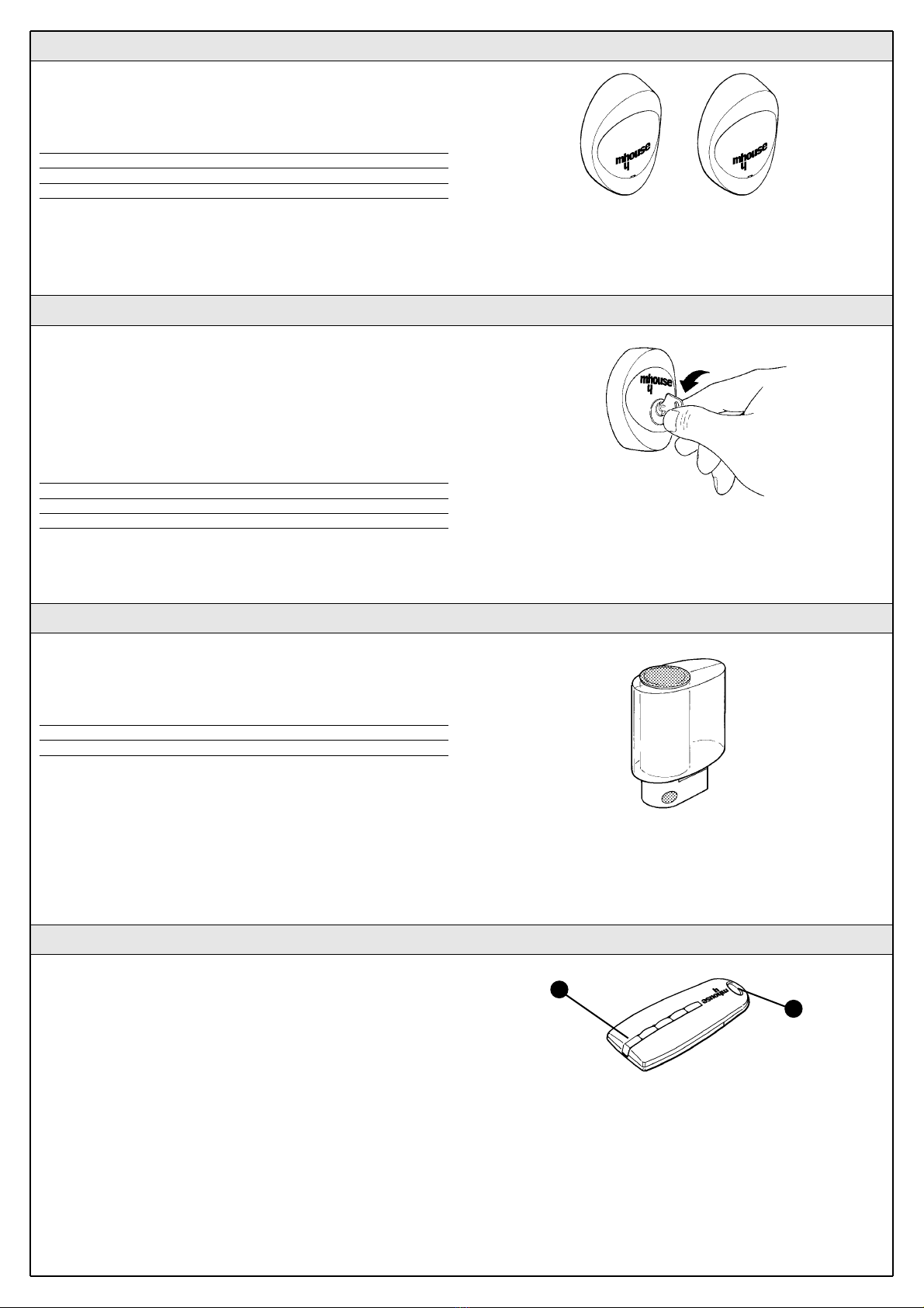
A) FL1 flashing light with incorporated aerial (optional)
B) KS1 key-operated selector switch (optional)
C) Pair of PH0 photocells (optional)
D) Mechanical stops
E) GD0K gearmotor
2.2 Description of the automation
A
B
Figure 1
2 Product description
2.1 Applications
GD0 is a set of components designed for the automation of sectional or
overhead doors in residential applications.
Any applications other than those described above or under dif-
ferent conditions from those specified in this manual are forbid-
den.
GD0 operates with electric power. In the event of a power failure, the
gearmotor can be released using a suitable cord in order to move the
door manually.
E
D
C

Instructions GD0 5
GD0 can consist of the devices shown in figure
2; make immediately sure that they correspond
to the contents of the package and verify the
integrity of the devices.
Note: to adapt GD0 to local regulations, the con-
tents of the package may vary; an exact list of
the contents is shown on the outside of the
package under the “Mhousekit GD0 contains”
heading.
Component and accessories list:
A) GD0K electromechanical gearmotor with
incorporated control unit.
B) head with pinion
C) carriage and release cord
D) 6 m belt
E) leaf bracket
F) 3 m guide in 3 sections
G) 4 coupling profiles
H) 2 ceiling-mounted brackets
I) Various small parts: mechanical stops,
screws, washers, etc. See tables 1, 2, 3
and 4 (*)
L) 1 TX4 radio transmitter.
M) PH0 pair of wall-mounted photocells
N) KS1 key-operated selector switch
O) FL1 flashing light with incorporated aerial.
* The screws required for mounting GD0 are
not supplied as they depend on the type of
material and its thickness.
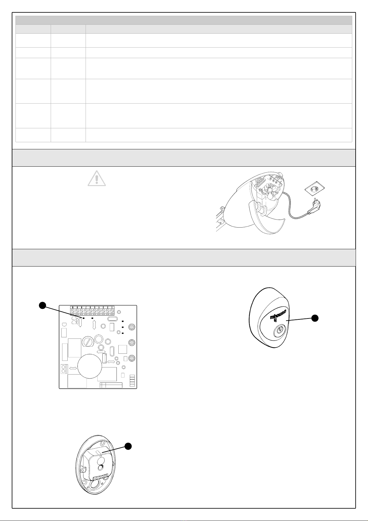
2.3 Description of devices
GD0K is an electromechanical gearmotor consisting of a 24V direct cur-
rent motor. It features a mechanical release mechanism with cord that
allows you to move the door manually in the event of a power failure.
The gearmotor is fixed to the ceiling with the relative mounting brackets.
The control unit actuates the gearmotors and provides for the control of
the supply of the different components; it features an electronic board
with incorporated radio receiver.
The control unit can actuate the gearmotor with two speeds: “slow” and
“fast”.
The three P1, P2 and P3 buttons [B] and the corresponding LED’s are
used to program the control unit.
A numbered terminal block is present for the electrical connections [A]. A
LED status signal is present in correspondence with the STOP input.
The connection to the power supply is very easy: just insert the plug in a
power outlet.
Table 1: List of small parts for a GD0K Q.ty
M6 self-tapping nuts 19 pcs
M6 x15 screws 18 pcs
6.3x45 tcei screws 4 pcs
4.2x9.5 screws 2 pcs
6x18 screw 1 pc
R05 washers 2 pcs
Cable membrane 1 pc
Mechanical stops 2 pcs
2.3.1 GD0K Electromechanical Gearmotor
Figure 3
Figure 2
ACB D
L M N
O
G H
I
A
B
E
F
6 Instructions GD0
Table 2: List of small parts for PH0 Q.ty
HI LO 4X9.5 screw 4 pcs
3.5X25 self-tapping screw 4 pcs
s 5 c nylon screw anchor 4 pcs
2.3.3 KS1 key-operated selector switch (optional)
Figure 5
2.3.4 FL1 flashing light with incorporated aerial (optional)
The flashing light is controlled by the control unit and signals danger
when the door is moving. Inside the flashing light there is also the aerial
for the radio receiver.
Figure 6
2.3.5 TX4 radio transmitter
The radio transmitter is used for the remote control of the door opening
and closing manoeuvres. It features four buttons that can all be used for
the 4 types of command to a single automation unit, or to control up to
4 different automation units.
The transmission of the command is confirmed by the LED [A]; an eyelet
[B] allows them to be hung on a keyring.
Figure 7
B
A
The pair of PH0 wall-mounted photocells, once they are connected to
the control unit, enables the detection of obstacles found on the optical
axis between the transmitter (TX) and the receiver (RX).
Table 3: List of small parts for KS1 Q.ty
HI LO 4X9.5 screw 2 pcs
3.5X25 self-tapping screw 4 pcs
s 5 c nylon screw anchor 4 pcs
The KS1 key-operated two-position selector switch enables door control
without using the radio transmitter. It is equipped with internal light for
locating in the dark.
There are two commands, which depend on the direction of rotation of
the key: “OPEN” and “STOP”; then the key, which is spring loaded,
returns to the centre position.
2.3.2 PH0 photocells (optional)
Figure 4
Table 4: List of small parts for FL1 Q.ty
4.2X32 self-tapping screw 4 pcs
s 6 c nylon screw anchor 4 pcs
Instructions GD0 7
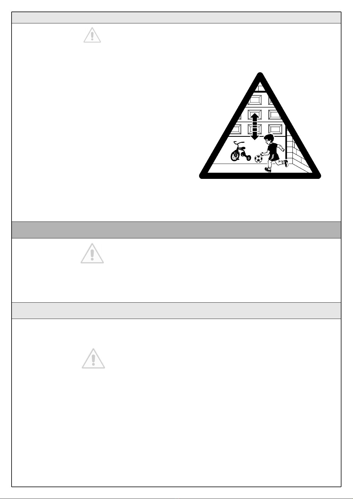
GD0 must not be used to power a door that is not efficient and
safe. It cannot solve defects resulting from incorrect installation
or poor maintenance of the door.
WARNING: incorrect installation could cause serious damage.
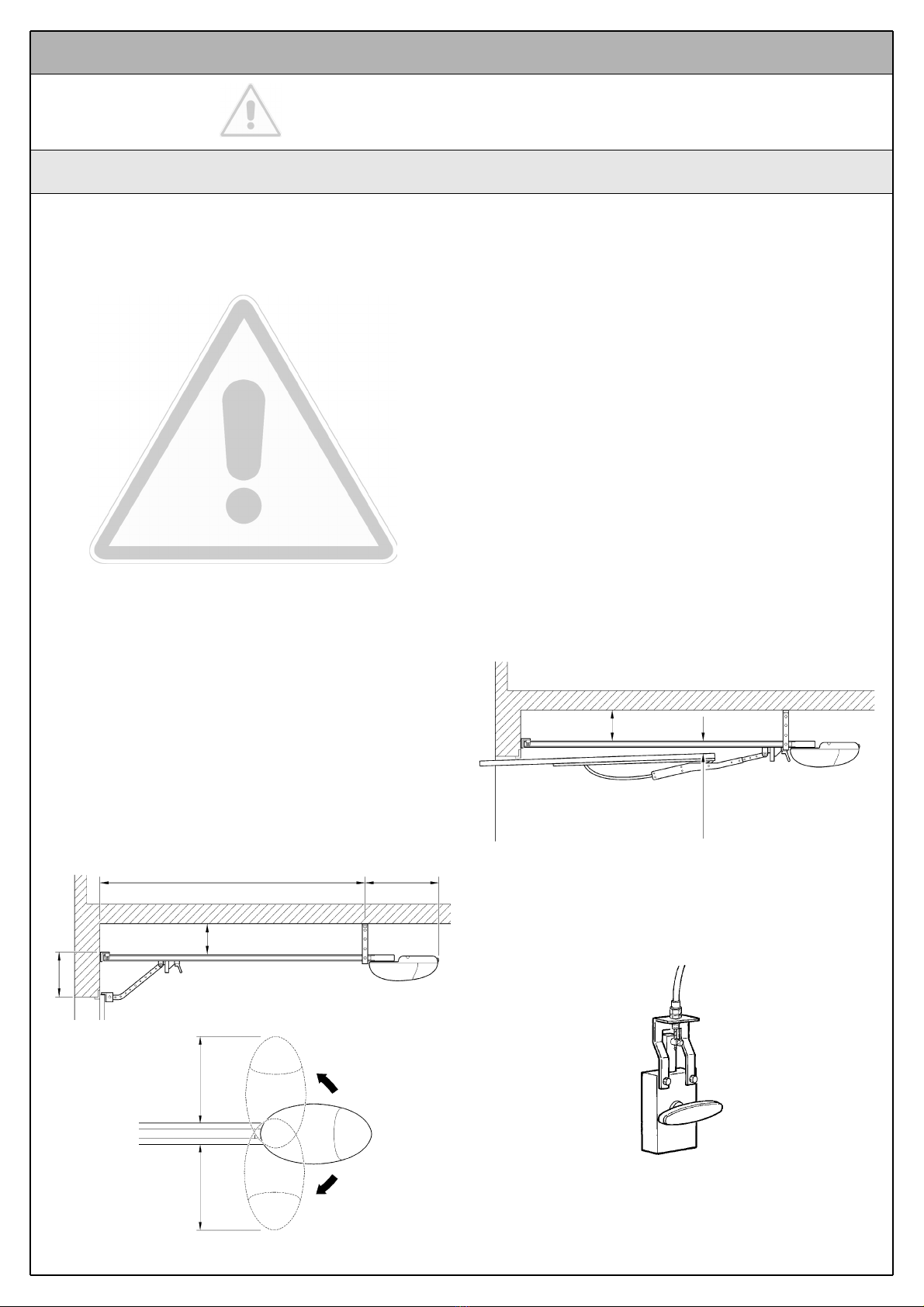
Before proceeding with the installation you must:
• Make sure that the door movement does not hinder roads or
public footpaths.
• After the motor has been installed, remove unnecessary cables
or chains and turn off any unneeded equipment
• Make sure that the weight and dimensions of the door fall with-
in the specified operating limits (Chapter 3.1.1). If they do not,
GD0 cannot be used.
• Make sure that the structure of the door is suitable for automa-
tion and in compliance with regulations in force.
• Make sure that there are no points of greater friction in the
opening or closing travel of the door.
• Make sure that the mechanical structure of the door is sturdy
enough and that there is no risk of derailing out of the guide.
• Make sure that the door is well balanced: it must not move by
itself when it is placed in any position.
• Make sure that the installation area is compatible with the size
of the gearmotor and that it is safe and easy to release it.
• Make sure that the mounting positions of the various devices
are protected from impacts and that the mounting surfaces are
sufficiently sturdy.
• Make sure that the mounting surfaces of the photocells are flat
and that they enable the proper alignment between TX and RX.
• Make sure that the minimum and maximum clearances speci-
fied in fig. 8 are observed.
• Pay attention in particular to the methods for securing the head
of the guide and the brackets to the ceiling. The head of the guide
will have to bear all the strain of opening and closing the door; the
ceiling-mounted brackets will have to bear all the weight of GD0.
In both cases, the wear and deformations that may occur in time
must be taken into consideration.
• The gearmotor should be mounted so that it coincides with the
centre of the door, or is slightly off-centre, e.g. in order to mount
the OSCILLATING ARM next to the handle (Figure 11).
• Make sure that, in the position corresponding to the door, or
slightly to the side, (see positions “A” and “B”) the conditions are
suitable for mounting the head of the guide; in particular, the
material should be sufficiently sturdy and compact.
Make sure that GD0 can be mounted on the ceiling along position
“C” using the mounting brackets.
If the door to be automated is an overhead type with springs or
counterweights, it will be necessary to install an OSCILLATING
ARM, which must be mounted next to the handle (Figure 11).
• Make sure that distance [E] in Figure 9, i.e. the minimum dis-
tance between the upper side of the guide and the maximum
point reached by the upper edge of the door, is no shorter than 65
mm and no longer than 300 mm, otherwise GD0 cannot be
installed.
If the door closes a room that has no other means of access, we
recommend installation of the EXTERNAL RELEASE KIT, other-
wise a simple power failure will prevent access to the room (fig-
ure 10).
Note: the oscillating arm and external release kit are supplied
with the related assembly instructions.
The installation must be carried out by qualified and skilled per-
sonnel in compliance with the directions provided in chapter 1
“WARNINGS”.
3 Installation
3.1 Preliminary checks
Figure 8
Figure 9
C 2970 mm D 410 mm
B 0÷400 mm
A 40÷400 mm
260 mm260 mm
B 0÷400 mm
E 65÷300 mm
Figure 10
8 Instructions GD0
3.1.1 Operating limits
3.1.2 Tools and Materials
Figure 12
Figure 11
Chapter 6 “Technical Characteristics” provides the fundamental data
needed to determine whether all the GD0 components are suitable for
the intended application.
In general GD0 is suitable for the automation of sectional and overhead
doors for residential applications having the following maximum dimensions:
Sectional doors: 240cm max. height - 300cm (7.2m2) max. width - max-
imum torque 55kg.
Overhead garage doors: 240cm max. height - 270cm (6.48m2) max.
width - maximum torque 55kg.
The shape of the door and the climatic conditions (e.g. presence of
strong wind) may reduce this maximum limit. In this case it is necessary
to measure the torque needed to move the door under the worst condi-
tions, and to compare it to the data provided in the technical character-
istics chart for the GD0 gearmotor.
Make sure you have all the tools and materials needed to install
the system; make sure that they are in good condition and serv-
iceable according to current safety standards. See examples in
figure 12.

Instructions GD0 9
3.1.3 List of cables
Figure 13
3.2 Preparing the Electrical System
E
3.2.1 Connection to the Electrical Mains
Although the connection of GD0 to the electrical mains is beyond the
scope of this manual, we wish to remind you that:
• The power supply line must be laid and connected by a qualified
professional electrician.
• Have a suitably protected 16A “schuko” outlet installed, where
you can plug in GD0.
• Make sure that the power supply cable does not hang over mov-
ing parts or hazardous areas.
• The electric line must be grounded and protected against short
circuits; a bipolar disconnection device must also be present with
contact separation of at least 3mm, which allows the power sup-
ply to be disconnected during the installation and maintenance of
the GD0.
With the exception of the plug and the power cable, the rest of the sys-
tem uses extra-low voltage (approx. 24V); the wiring can therefore be
done by personnel that is not properly qualified, provided that all the
instructions in this manual are carefully observed.
After selecting the position of the various devices (refer to figure 13) you
can start preparing the conduits for the electrical cables connecting the
devices to the control unit.
The shock-resistant conduits are designed to protect the electrical
cables and prevent accidental breakage.
Install any fixed control close to the door but away from moving parts and
at a height of 1.5m.
WARNING: the cables used must be suitable for the type of installation; for example, an H03VV-F type cable is recommended for indoor
applications.
Note 1: For the PHOTO, STOP and OPEN cables, there are no special contraindications to the use of a single cable that groups together multiple
connections; for example, the STOP and OPEN inputs can be connected to the KS1 selector switch using a single 4x0.25mm2cable.
Table 5: List of cables
Connection Cable type Maximum length allowed
[A] STOP input 2x0.25mm2cable 20m (note 1)
[B] OPEN input 2x0.25mm2cable 20m (note 1)
[C] PHOTO input TX 2x0.25mm2cable
RX 2x0.25mm2cable 20m (note 1)
[D] FLASH light output 2x0.5mm2cable 20m
[E] Radio aerial RG58 type shielded cable 20m (recommended less than 5m)
The cables required for the installation of GD0 may vary depending on the type and quantity of devices to be installed; figure 13 shows the cables
needed for a typical installation; no cable is supplied with GD0.
D
B
A
C
C

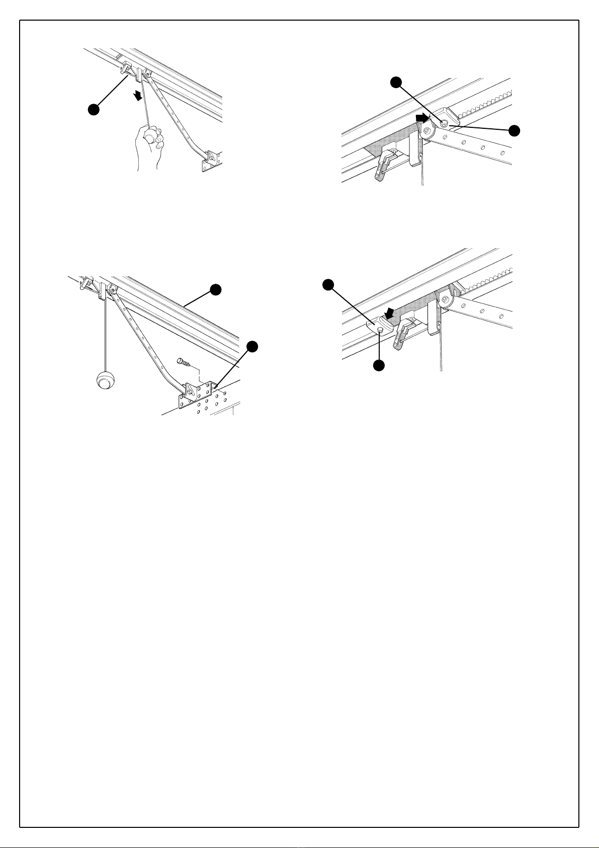
The guide supplied with the GD0 must be assembled as follows:
1 Position the three parts which make up the guide so that they can be
connected together.
2 Pass one end of the belt through the tightener [A], as in fig. 14.
3Pass the same end through the head [B], as in fig. 15. taking care that
the belt is correctly positioned: the teeth should be facing inwards, and
should be straight with no twists
4 Turn the lower carriage as in fig. 16.
5 Place both ends of the belt in all of the shaped slots of the lower car-
riage [C], and fix the two ends with the two V4.2x9.5 screws and two
R05 washers, as in fig. 17.
6 Fix the leaf bracket [D] to the upper carriage [E] with the V6x18 screw
and related washer as in fig. 18.
7 Hook the upper carriage [E] to the lower carriage [C] and place the
entire carriage assembly inside the guide, as in fig. 19.
8 Assemble the Guide [B] head as in fig. 20. This operation requires a
particular amount of force, so if necessary use a rubber hammer
9 Connect the three parts [G] together using the connection brackets [F],
as in fig 21 and 22.
10 Stretch the belt with the M8 bolt [H], as in fig. 23, until it is sufficient-
ly taut.
10 Instructions GD0
3.3 Installation of the Various Devices
3.3.1 Guide assembly
The GD0 installation is made up of three parts:
- Guide assembly (see paragraph 3.3.1).
- Fixing of the gearmotor to the guide (see paragraph 3.3.2).
- Fixing of the gearmotor to the ceiling (see paragraph 3.3.3).
Figure 14
Figure 18
Figure 19
Figure 20
Figure 15
Figure 16
Figure 17
A
B
C
D
E
E
C
B
F
F
G
G
G
Figure 21
Figure 22
Figure 23
H

Instructions GD0 11
1Couple the GD0K gearmotor’s shaft extension with the head of the
guide [B], then secure them using the four M6.3x38 screws [I],
The gearmotor can be rotated in three different positions
1Observing the A, B and C positions shown in Figure 8, mark the 2 fas-
tening points for the guide’s front bracket in the centre of the garage door
(or slightly off-centre – Figure 11).
Depending on the type of material, the front bracket can be fastened
using rivets, anchors or screws (Figure 26). If positions A, B, and C (fig-
ure 8) allow it, the bracket can be fastened directly to the ceiling.
2After drilling the holes, leave the head of the gearmotor on the ground,
lift the guide from the front and secure it with two screws, anchors or riv-
ets depending on the type of surface.
3Secure the mounting brackets [L], using the screws [M] and nuts [N],
and choosing the hole that is closest to the established position B (see
Figure 8).
4Using a ladder, lift the gearmotor and position the brackets against the
ceiling. Mark the drilling points, then put the gearmotor back on the
ground.
5Using a ladder, drill the marked positions and place the brackets over
the holes which have just been drilled and, using suitable screws and
plugs, secure the brackets.
6 Make sure that the guide is perfectly horizontal, then cut the excess of
the brackets using a hacksaw.
3.3.2 Fixing of the gearmotor to the guide
3.3.3 Fixing of the gearmotor to the ceiling
Figure 24 Figure 25
Figure 26
B
I
Figure 27
Figure 28
N
MPosition B
L
Figure 29
Figure 30
7 With the door closed, pull the cord and release the carriage [E] from the
guide.
8 Slide the carriage until the door mounted bracket [D] shown in Figure
32 is positioned on the upper edge of the door, exactly perpendicular to
the guide [G].
Next, secure the door mounted bracket [D] with screws or rivets. Use
screws or rivets that are suitable for the door material, making sure that
they are capable of bearing all the strain resulting from opening and clos-
ing the door.
9 Loosen the screws in the two mechanical stops, then place the front
mechanical stop [O] before the carriage (Figure 33). Push the carriage
hard in the closing direction and, in the reached position, tighten the
screw firmly [P].
10 Open the door manually to the desired open position, then place the
rear mechanical stop [Q] near the carriage (Figure 34), and secure it tight-
ening the screw firmly [R].
11 Make sure that the release cord can be activated at a height less than
1.8m.
12 Instructions GD0
Figure 32
Figure 33
Figure 34
G
D
O
P
Q
R
Figure 31
E

Instructions GD0 13
3.3.5 KS1 key-operated selector switch (optional)
1Determine the position of the selector switch; it must be installed out-
doors, alongside the gate and at a height of approx. 80 cm, so that it can
be used by people of different height.
2Remove the front glass [A] by prising it out with a slotted tip screwdriver
applied to the bottom.
3To separate the bottom from the shell you need to insert the key and
keep it turned, then pull with a finger inserted in the hole for the passage
of the cables.
4Breach the four holes at the bottom with a screwdriver; mark the drilling
points using the bottom as reference; make sure that the hole in the bot-
tom matches the outlet for the cables.
5Drill the holes in the wall using a hammer drill with a 5 mm bit and insert
the 5 mm screw anchors.
Figure 40
A
Figure 41
3.3.4 PH0 Photocells (optional)
11 Select the position of the two elements that make up the photocell
(TX and RX) observing the following directions:
Position them at a height of 20-25 cm from the ground, on both sides of
the area to be protected and as close as possible to the edge of the door.
With sectional doors, the photocells can be mounted outside, whereas
with overhead doors they can only be mounted inside (outside they
would obstruct the movement of the door)
• Point transmitter TX towards receiver RX, with a maximum tolerance of 5°.
• In the selected locations there must be a conduit for threading the
cables.
2Remove the front glass [A] by prising it out with a slotted tip screwdriver
applied to the bottom.
3Press the lens in order to separate the two shells.
4Breach two of the four holes [B] at the bottom with a screwdriver.
5Position the photocell at the point where the conduit arrives; the hole
at the bottom [D] should match the point where the cables come out of
the wall; mark the drilling points using the bottom as reference.
6Drill the holes in the wall using a hammer drill with a 5 mm bit and insert
the 5 mm screw anchors.
7Secure the bottom with the screws [C] .
8 Connect the electric cable to the appropriate TX and RX terminals. See
paragraph 3.3.7 for electrical connections “Electrical connections to the
GD0K control unit” and 5.3.1 “Phototest output”.
9Secure the cover shell [E] using the two screws [F] and a Phillips screw-
driver. Then insert the glass [G], pressing it gently to close it.
Figure 36
Figure 38
Figure 39
E
F
G
Figure 35
A
B
Figure 37
B
C
D
B
14 Instructions GD0
6Secure the bottom using the four screws [A].
7Connect the electric cables to the appropriate OPEN and STOP
terminals, as shown in figure 43. It is not necessary to observe any
polarity. The terminals can be removed in order to facilitate the
operations; make the connections and then reinsert them.
8To insert the shell on the bottom you need to turn the key. After you
have inserted it, turn the key back to the centre position.
9Secure the body [C] using the two screws [D] and a Phillips
screwdriver. Finally insert the glass [E], pressing it gently to close it (Figure
44).
Figure 43
Figure 42
A
Figure 44
E
D
C
1Determine the position of the flashing light: it should be near the door
and easy to see; it can be secured to a horizontal as well as vertical sur-
face.
2Slide out the diffuser [A] from the bottom by pressing the two buttons [B].
3Separate the lamp holder with the aerial from the base.
4Breach the four holes for the screws and the hole for the passage of
the cables in the bottom or side, depending on the installation position,
using a screwdriver.
5Mark the drilling points using the bottom as reference and make sure
that the hole in the bottom matches the outlet for the cables.
6Drill the holes in the wall using a hammer drill with a 6 mm bit and insert
the 6 mm screw anchors.
7Secure the bottom with the screws [C].
8Connect the electrical cables to the appropriate FLASH and “aerial” ter-
minals as shown in figure 48. You do not need to observe any polarity on
the FLASH terminal; however, for the connection of the shielded cable to
the aerial, connect the braid as shown in figure 49. The terminals can be
removed in order to facilitate the operations; make the connections and
then reinsert them (Figure 50).
9Fit the lamp holder on the base and press it down until it snaps into
position.
10 Slide in the diffuser, pressing the buttons and fitting it on the bottom.
Rotate it in the desired direction then press it down until the two buttons
snap into their seat.
3.3.6 FL1 flashing light (optional)
Figure 45
Figure 46
A
B
Figure 47 Figure 51
Figure 48 Figure 49 Figure 50
C
C
Instructions GD0 15
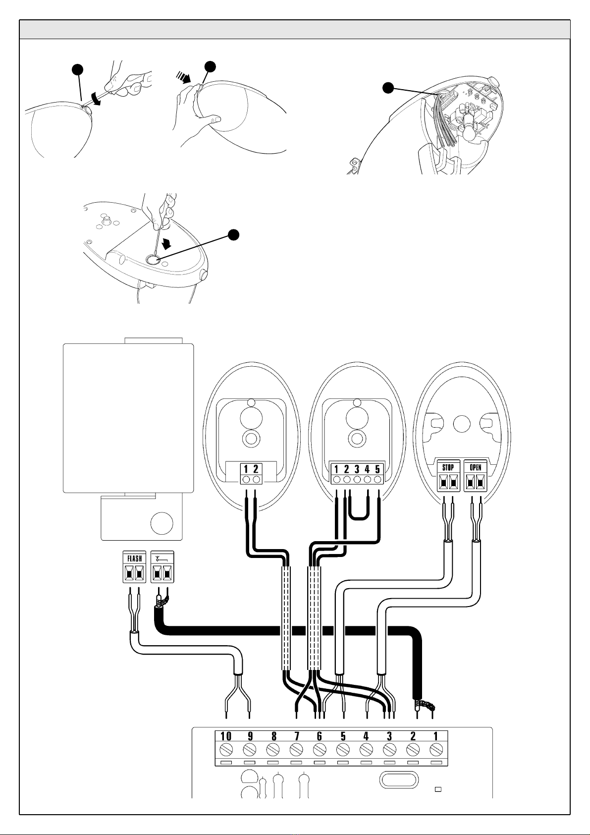
1Unscrewing screw [A] and pushing button [B], open the lid.
2Remove the circular part [C] with a screwdriver, as in fig. 54.
3 Cut the rubber membrane [D] so that the cables can pass and insert it
in the hole [C].
4Use Fig. 56 and the connection description in Table 6 as reference.
• if using the PH0 photocell, remove the small piece of wire between ter-
minals 3 and 7 and make the connections as in Fig. 56.
• if using the flashing light aerial, remove the piece of wire, which is con-
nected to terminal 2, and connect the RG58 type shielded cable.
4When the connections have been completed secure the cables using
suitable clamps.
5To close the cover, turn and push until a click is heard. Secure the
screw [A].
3.3.7 Electrical connections to the GD0K control unit
Figure 52 Figure 53
Figure 56
A
Figure 54
C
Figure 55
D
FL1
B
TX RXPH0 KS1
16 Instructions GD0
3.4 Power Supply Connection
The connection of the GD0 control unit to the mains must be
made by a qualified electrician.
To carry out tests, insert the plug for GD0K in a power outlet; if neces-
sary, use an extension cord.
Figure 57
3.5 Initial checks
As soon as the control unit is energized, you should check the following:
1Make sure that the LED [A] flashes regularly, with about one flash per
second.
2If the system is equipped with the PH0 photocells, make sure that the
SAFE LED [B] shown in figure 59 flashes (on both TX and RX). The type
of flashing is irrelevant, it depends on other factors; what matters is that
it is not always off or always on.
3If the system is equipped with the KS1 key-operated selector switch,
make sure that the night light [C] is on.
4If the above conditions are not satisfied, you should immediately switch
off the power supply to the control unit and check the cable connections
more carefully. For more useful information see also chapters 5.5 “Trou-
bleshooting” and 5.6 “Diagnostics and Signals”.
Figure 58
Figure 60
Figure 59
B
C
A
Table 6
Terminals Functions Description
1-2 Aerial radio receiver aerial connection input. The FL1 has a built-in aerial, alternatively an external aerial can be used or the small
piece of wire that is already connected to the terminal can be left, which acts as an aerial.
3-4 OPEN input for manoeuvre control devices; “Normally Open” type contacts can be connected.
5-6 STOP
input for the devices which block or eventually stop the manoeuvre in progress. Contacts like “Normally Closed”, “Normally
Open” or constant resistance devices can be connected using special procedures on the input. Additional information on
STOP can be found in paragraph “5.3.2 STOP input”.
3-7 PHOTO
Input for safety devices such as PH0 photocells. Cut-in during closure, inverting the manoeuvre.
“Normally Closed” contacts can be connected. The PHOTO input is factory set short-circuited by means of a jumper
between inputs 3 and 7 of the terminal. Additional information on PHOTO can be found in paragraph “3.3.4 PH0 Photo-
cells (optional)”.
6-8 Phototest
All safety devices are controlled each time a manoeuvre is performed and the manoeuvre is only performed if the test has a
positive outcome. This is possible by means of a special connection; the “TX” photocell transmitters are powered separate-
ly in respect to the “RX” receivers. Additional information on connections can be found in paragraph “5.3.1 Phototest out-
put”.
9-10 Flashing light An FL1 flashing light with a 12V 21W car bulb can be connected to this output. During the manoeuvre the unit flashes at
intervals of 0.5 s.

Instructions GD0 17
The opening and closing positions of the door must be recognised by the
control unit. In this phase, the door stroke from the mechanical closing
stop to the mechanical opening stop is detected. In addition to the posi-
tions, the STOP input configuration and the presence or non-presence of
the PHOTO input “Phototest” mode connection are also detected and
memorised in this phase.
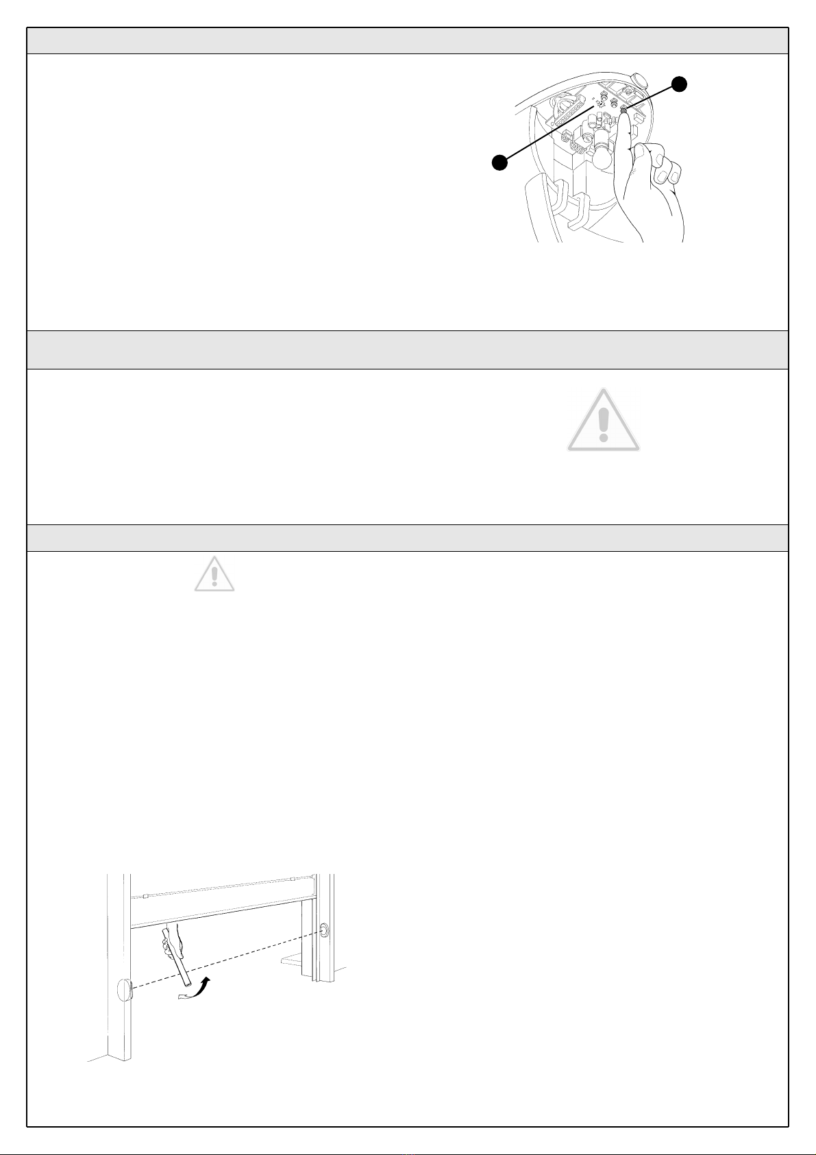
1Make sure that the carriage is attached.
2Press key P3 [A] on the control unit and hold it down for at least three
seconds, then release the key (Figure 61).
• Wait until the control unit has completed the recognition stage: closing,
opening and re-closing of the door.
• If any device is triggered during the recognition stage, or the P3 key is
pressed, the recognition stage will be immediately interrupted. In this
case it must be repeated from the beginning.
• During the recognition stage the courtesy light will flash just like the
flashing light.
3An error has occurred if the LEDs P2 and P3 [B] are flashing at the end
of the recognition stage. See paragraph 5.5 “Troubleshooting”.
4Press button 1 of the “TX4” transmitter to perform a complete opening
manoeuvre. Then push it again to perform a complete closing manoeu-
vre. The control unit memorises the necessary force throughout the trav-
el during these two manoeuvres.
It is important that these two first manoeuvres are not interrupted by any
commands. If the manoeuvres are not completed, repeat the recognition
procedure starting from step 1.
The position recognition stage can be repeated at any time in the future
(for instance, if one of the mechanical stops is moved); just repeat start-
ing from step 1.
WARNING: if the belt is not tightened properly, during the search
for the positions it may slip on the pinion. If this happens, stop the
leaning procedure by pressing key P3 and stretch the belt by
tightening the nut [D]. Then repeat the recognition procedure
starting from step 1.
3.5.1 Recognition of the door’s open and closed positions
Figure 61
BA
Figure 62
D
3.5.2 Testing the radio transmitter
To test the transmitter just press one of its 4 keys, make sure that the red
LED flashes and that the automation carries out the related command.
The command associated to each button depends on how it has been
memorized (see paragraph 5.4 “Memorization of Radio Transmitters”).
The transmitter supplied has already been memorized and when you
press the buttons the following commands are transmitted:
Button T1 “OPEN” command
Button T2 “Open partially” command
Button T3 “Open only” command
Button T4 “Close only” command
T1
T2
T3
T4
Figure 63
3.6 Regulations
3.6.1 Selecting door speed
The door can be opened and closed at two speeds: “slow” or “fast”.
To switch from one speed to the other press the P2 button [B] momen-
tarily; the corresponding P2 LED [A] will light up or go off; if the LED is off
the speed is “slow”, if the LED is on the speed is “fast”.
Figure 64
A
B
The opening and closing of the door can take place according to differ-
ent operating cycles:
• single cycle (semiautomatic): the door opens with a command and
stays open until the next command is given, causing it to close.
• complete cycle (automatic closing): the door opens with a command
and then closes automatically after a short time (for the time, see para-
graph 5.1.1 “Adjusting the parameters with the radio transmitter”).
To switch from one operating cycle to the other, press the P3 button [B]
momentarily; the corresponding LED P3 [A] will light up or go off; if the
LED is off the cycle is “single”, if the LED is on the cycle is “complete”.
18 Instructions GD0
3.7 Testing and Commissioning
These are the most important operations, designed to guarantee the
maximum safety and reliability of the automation system.
The testing procedure can also be used as a periodic check of the
devices that make up the automation.
The testing and commissioning operations must be performed by
qualified and experienced personnel who must establish what
tests should be conducted based on the risks involved, and veri-
fy the compliance of the system with applicable regulations, leg-
islation and standards, in particular with all the provisions of EN
standard 12445 which establishes the test methods for sectional
and overhead door automation systems.
3.6.2 Selecting the type of operating cycle
Figure 65
B
A
1 Make sure that the provisions contained in chapter 1 “WARN-
INGS” have been carefully observed.
2Using the selector switch (if provided) or the radio transmitter, test the
opening and closing of the door and make sure that the door moves in
the intended direction.
The test should be carried out a number of times to make sure that the
door moves smoothly, that there are no points of excessive friction and
that there are no defects in the assembly or adjustments.
3Check the proper operation of all the safety devices, one by one (pho-
tocells, sensitive edges, etc.). In particular, each time a device is activat-
ed the “ECSBus” LED on the control unit flashes for a longer time, con-
firming that the control unit recognizes the event.
4To check the photocells (if provided) pass a 5 cm diameter, 30 cm long
cylinder on the optical axis, first near TX, then near RX and finally at the
mid-point between them and make sure that in all these cases the device
is triggered, switching from the active to the alarm status and vice-versa;
finally, that it causes the intended action in the control unit, for example
that it causes the reversal of the movement during the closing manoeu-
vre.
5Measure the impact force according to EN standard 12445. If “motor
force” control is used to assist the system for the reduction of the impact
force, try to find the adjustment that gives the best results.
6Ensure that the entire mechanism is correctly adjusted and that the
automation system inverts the manoeuvre when the door collides with a
50 mm high object on the floor.
7Ensure that the automation prevents or blocks the opening manoeuvre
when the door is loaded with a mass of 20 Kg, fixed in the middle of the
doors lower edge.
3.7.1 Testing
Figure 66
Instructions GD0 19
4.1 Dismantling and Disposal
GD0 is constructed of various types of materials, some of which can be
recycled (aluminium, plastic, electric cables), while others must be dis-
posed of (electronic boards).
WARNING: some electronic components may contain polluting
substances; do not pollute the environment. Enquire about the
recycling or disposal systems available for GD0 in compliance
regulations locally in force.
1Disconnect the system from the electrical mains by pulling the plug.
2Disassemble all the devices and accessories, following in reverse order
the procedures described in chapter 3 “Installation”.
3Remove the batteries from the radio transmitters.
4Remove the electronic boards.
5Sort the various electrical and recyclable materials and consign them
to licensed firms for recovery and disposal.
6Consign the remaining materials to authorized scrap collection centres.
The maintenance operations must be performed in strict compli-
ance with the safety directions provided in this manual and
according to the applicable legislation and standards.
The devices used for the GD0 automation system do not require any
special maintenance. However, periodically make sure (at least once
every six months) that all the devices are perfectly efficient.
To this end, carry out all the tests and checks described in paragraph
3.7.1 “Testing” and the operations described in paragraph 7.3.3 “Main-
tenance Operations to Be Performed by the User”.
If other devices are present, follow the directions provided in the corre-
sponding maintenance schedule.
4 Maintenance
3.7.2 Commissioning
The commissioning operations can be performed only after all the
tests have been successfully carried out. Partial commissioning
or implementation of “temporary” conditions are not permitted.
1Prepare the technical documentation for the automation, which must
include at least: assembly drawing (e.g. figure 1), wiring diagram (e.g. fig-
ure 56), analysis of hazards and solutions adopted, manufacturer’s dec-
laration of conformity of all the devices installed. For GD0 use Annexe 1
“EC Declaration of Conformity of the GD0 components”
2Post a label on the door providing at least the following data: type of
automation, name and address of manufacturer (person responsible for the
“commissioning”), serial number, year of manufacture and “CE” marking.
3Fill out the declaration of conformity and deliver it to the owner of the
automation system; for this purpose you can use Annexe 2 “EC Decla-
ration of Conformity”.
4Prepare the operating guide and deliver it to the owner of the automa-
tion system; Annexe 3 “OPERATING GUIDE” can be used as an exam-
ple.
5Prepare the maintenance schedule and deliver it to the owner of the
automation system; it must provide directions regarding the maintenance
of all the automation devices.
6Post a permanent label or sign detailing the operations for the release
and manual manoeuvre (use the figures in Annex 3 “Operating guide”).
7Before commissioning the automation system inform the owner
regarding dangers and hazards that are still existing.
8Post a permanent label or sign with this image on the door (minimum
height 60 mm) with inscription WARNING – RISK OF CRUSHING.
Figure 67
20 Instructions GD0
The parameter adjustment operation can be performed using a radio
transmitter, provided it is memorized in mode 1 like the one supplied. If
no transmitter memorized in Mode 1 is available, you can memorize one
just for this phase and delete it immediately afterwards (see paragraph
5.4.1 “Mode 1 memorization” and paragraph 5.4.4 “Deleting a radio
transmitter”).
WARNING: when using the transmitter to make adjustments you need
to give the control unit time to recognize the radio command; this means
that the buttons must be pressed and released slowly, held down for at
least one second, then released for one second and so on.
1Press buttons T1 and T2 on the radio transmitter simultaneously for at
least 5s.
2Release the two buttons.
3Within 3 seconds, perform the action described in Table 7 based on
the parameter to be modified.
Example: to set the pause time at 60 s.
1st Press buttons T1 and T2 and hold them down for at least 5s
2nd Release T1 and T2
3th Press button T1 three times
All the parameters can be adjusted as required without any contraindi-
cation; only the adjustment of the “motor force” requires special care:
• Do not use high force values to compensate for points of abnormal fric-
tion on the door. Excessive force can compromise the operation of the
safety system or damage the door.
• If the “motor force” control is used to assist the impact force reduction
system, measure the force again after each adjustment in compliance
with EN standard 12445.
• The weather conditions may affect the movement of the door, therefore
periodic re-adjustments may be necessary.
Figure 68
T1 T2
1° Low Press button T3 once
2° Medium Press button T3 twice
3° High (*) Press button T3 three times
Motor force
“OPEN” function
1° “Open”-“Stop”-“Close”-“Stop” Press button T2 once
2° “Open”-“Stop”-“Close”-“Open” (*) Press button T2 twice
3° “Open”-“Open”-“Open”-“Open” (opening only) Press button T2 three times
The following chapters describe different ways of customizing GD0 to
make it suitable for specific application requirements.
5 Additional Information
5.1 Advanced Adjustments
5.1.1 Adjusting the Parameters with the Radio Transmitter
The radio transmitter can be used to adjust certain control unit operation
parameters: there are four parameters and each of them can have four
different values:
1) Pause time: time during which the door remains open (in the automatic
closing mode).
2) “OPEN” function: sequence of movements associated to each
“OPEN” command.
3) Motor force: maximum force beyond which the control unit recognizes
an obstacle and reverses the movement.
Table 7
Parameter N° Setting Action: operation to be performed at point 3 in the adjustment phase
Pause time
1° 15s Press button T1 once
2° 30s (*) Press button T1 twice
3° 60s Press button T1 three times
(*) Original factory setting
With a radio transmitter memorized in Mode 1 you can check the values
set for each parameter at any time by following the sequence described
below:
1 Press buttons T1 and T2 on the radio transmitter simultaneously for at
least 5s.
2 Release the two buttons.
3 Within 3 seconds, perform the action described in Table 8 based on
the parameter to be checked.
4 Release the button when the flashing light starts flashing.
5 Count the flashes and, based on their number, check the correspon-
ding value in table 7.
Example. If the flashing light flashes three times after you have pressed
T1 and T2 for 5s and then button T1, the pause time is set at 60s.
5.1.2 Checking the Adjustments with the Radio Transmitter
Table 8
Parameter Action
Pause time Press button T1 and hold it down
“OPEN” function Press and hold button T2
Motor force Press button T3 and hold it down
Other manuals for GD0
1
Table of contents
Other Mhouse Door Opening System manuals

Popular Door Opening System manuals by other brands


Besam
Besam Swingmaster MP Installation, adjustment and maintenance instructions

Assa Abloy
Assa Abloy SARGENT 1431 Series instructions

GAL
GAL MOVFR Quick setup

Häfele
Häfele Finetta T 70 VF manual

AGS
AGS D-PL Instructions for fitting, operating and maintenance

Stanley
Stanley MA900ñ Installation and owner's manual

WITTUR
WITTUR Hydra Plus UD300 Instruction handbook

Alutech
Alutech TR-3019-230E-ICU Assembly and operation manual

Pamex
Pamex KT-INP35 Installation instruction

MPC
MPC ATD ACTUATOR 50 ATD-313186 Operating and OPERATING AND INSTALLATION Manual

Chamberlain
Chamberlain T user guide

Dorma
Dorma MUTO COMFORT M DORMOTION 50 Mounting instruction