MHS Boilers CRUZ belt Instruction manual

INSTALLATION,OPERATION,MAINTENANCE
MANUAL
CRUZ®belt

CRUZbelt
2
E0032544Rev090710

CRUZbelt
3
E0032544Rev090710
CRUZbelt INDEX
Purpose .................................................................................................................................. 4
Equipment Warranty............................................................................................................... 5
Warning and Safety Instructions............................................................................................. 6
Introduction............................................................................................................................. 8
Receiving and Unpacking....................................................................................................... 8
Site Preparation.................................... .................................................................................. 8
Floor Support Information..................... .................................................................................. 8
Floor Support Installation........................................................................................................ 9
Ceiling Hanger Installation...................................................................................................... 9
Ceiling Hanger Sway Bracing................ ................................................................................. 9
Anchoring Ceiling Hangers.................... ............................................................................... 10
Conveyor Set-up................................................................................................................... 11
Electrical ............................................................................................................................... 12
Belt Tracking......................................................................................................................... 14
Commissioning of Equipment ............................................................................................... 16
Preventive Maintenance ........................................................................................................17
Maintenance Schedule.......................................................................................................... 18
Troubleshooting – Belt.......................................................................................................... 19
Troubleshooting – Gearmotor............................................................................................... 21
Troubleshooting – Chain and Sprocket................................................................................. 23
Troubleshooting – Bearings.................................................................................................. 24
Replacement Parts ............................................................................................................... 25
Mission.................................................................................................................................. 46

CRUZbelt
4
E0032544Rev090710
PURPOSE
It is the intent of MHS Conveyor, through
this manual, to provide information that acts as a
guide in the installation, operation and
maintenance of MHS Conveyor CRUZbelt
conveyors.
This manual describes basic installation
practices, assembly arrangements, preventive
maintenance and assists in replacement parts
identification.
This service manual is intended for use
by personnel who are knowledgeable of
installation and safe working practices on
conveyor systems.
Not all applications and conditions can be
covered; therefore, this manual is to be used
ONLY as a guide.
If additional copies of this manual are needed or if
you have any question concerning the
conveyor please contact your Business
Partner or MHS Conveyor' Customer Support
at 231-798-4547 or Fax 231-798-4146.

CRUZbelt
5
EQUIPMENT WARRANTY
MHS Conveyor warrants that the material and workmanship entering into its equipment is
merchantable and will be furnished in accordance with the specifications stated.
MHS Conveyor agrees to furnish the purchaser without charge any part proved defective within 2
years from date of shipment or before the equipment has forty-one hundred (4100) hours of
running use, whichever period is shorter, provided the purchaser gives MHS Conveyor immediate
notice in writing and examination proves the claim that such materials or parts were defective when
furnished. For drive components specific to XenoROL® (i.e. Xeno belts, slave Xeno belts, drive
spools, standard and speed-up, and spacers), this warranty shall be extended to five years or ten
thousand (10,000) hours of running use, whichever period is shorter, provided the conveyors are
applied, installed and maintained in accordance with MHS Conveyor published standards. Other
than the above, there are no warranties which extend beyond the description on the face hereof.
Consequential damages of any sort are wholly excluded.
The liability of MHS Conveyor will be limited to the replacement cost of any defective part. All
freight and installation costs relative to any warranted part will be at the expense of the purchaser.
Any liability of MHS Conveyor under the warranties specified above is conditioned upon the
equipment being installed, handled, operated, and maintained in accordance with the written
instructions provided or approved in writing by MHS Conveyor.
The warranties specified above do not cover, and MHS Conveyor makes no warranties which
extend to, damage to the equipment due to deterioration or wear occasioned by chemicals,
abrasion, corrosion or erosion; Purchaser's misapplication, abuse, alteration, operation or
maintenance; abnormal conditions of temperature or dirt; or operation of the equipment above rated
capacities or in an otherwise improper manner.
All equipment and components not manufactured by MHS Conveyor carry only such warranty as
given by the manufacturer thereof, which warranty MHS Conveyor will assign or otherwise make
available to Purchaser without recourse to MHS Conveyor, provided that such warranty is
assignable or may be made available.
IMPORTANT
For service on motors, reduction units, electrical components, controls, air or hydraulic cylinders,
contact the local authorized sales and service representative of respective manufacturer. If none is
available in your locality, contact the MHS Conveyor representative. MHS Conveyor will not be
responsible for units that have been tampered with or disassembled by anyone other than the
authorized representative of the respective manufacturer.
THERE ARE NO WARRANTIES, EXPRESSED OR IMPLIED, INCLUDING, BUT NOT LIMITED
TO, WARRANTIES OF MERCHANTABILITY OR FITNESS FOR A PARTICULAR PURPOSE,
EXTENDING BEYOND THOSE SET FORTH IN THIS STATEMENT OF WARRANTY.
Rev 04/08/2009
E0032544Rev090710

CRUZbelt
6
E0032544Rev090710
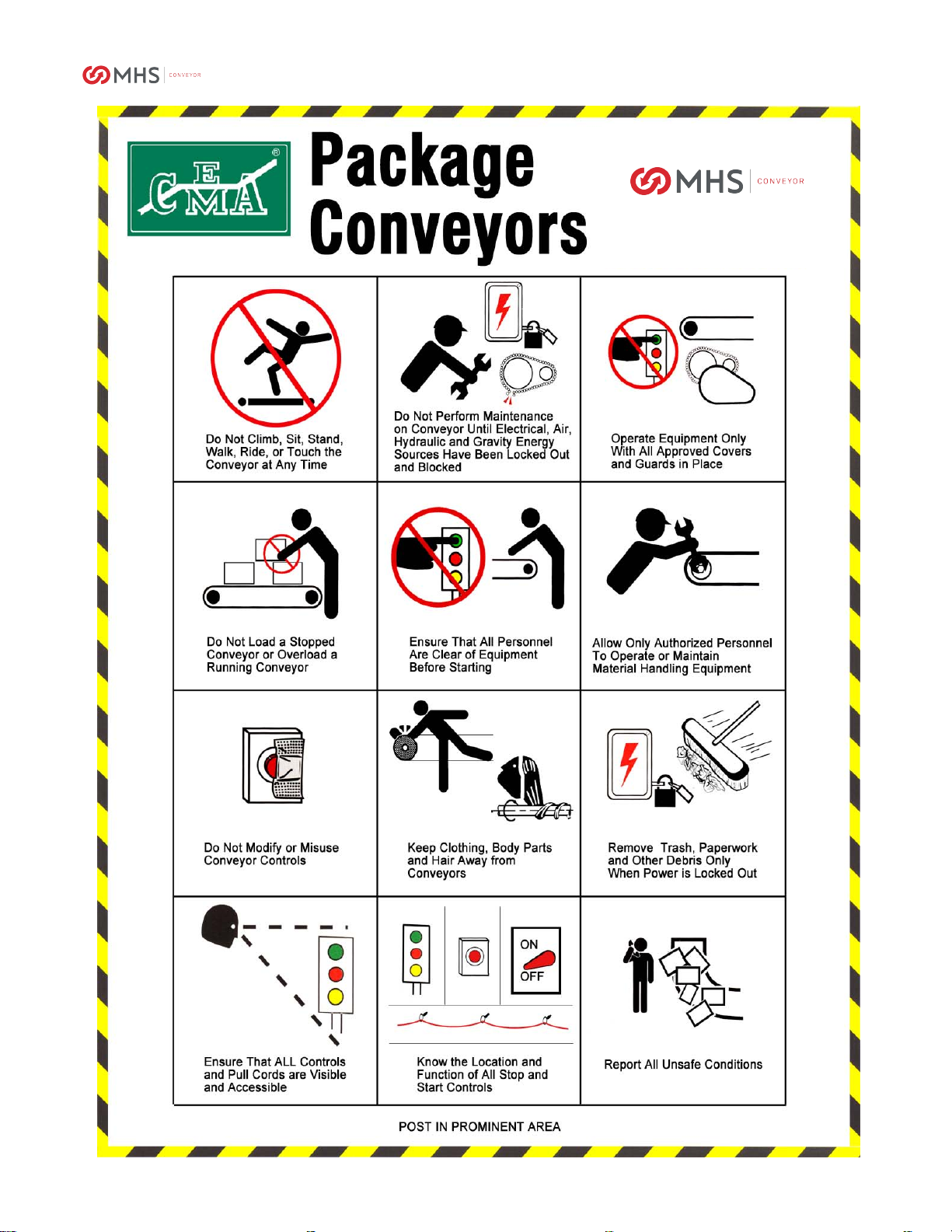
WARNINGS AND SAFETY INSTRUCTION
MHS Conveyor CRUZbelt conveyor is shipped
with safety equipment installed. This
equipment includes guarding, warning labels,
and pop-out rollers. All safety equipment
must be in place before running any conveyor.
Read and obey all warning labels. Any labels
damaged during the life of the conveyor will be
replaced free of charge.
Walking on or riding moving conveyor
is prohibited. Lock out power before removing
any guarding. Loose clothing and long hair
must be kept away from moving equipment.
Special attention must be paid to the
following areas of this manual:
WARNING
This is a notice which, if not followed, could result
in serious injury or death.
CAUTION
This is a notice which, if not followed, could result
in damage to equipment.
NOTE
This is where you will be notified of helpful
information.
CRUZbelt
7
E0032544Rev090710

CRUZbelt
8
E0032544Rev090710
INTRODUCTION
This manual provides information for
installing, operating, and maintaining your
MHS Conveyor CRUZbelt conveyor. A complete
parts list has been provided, along with a list of
recommended spare parts. Important safety
information is included throughout this manual.
MHS Conveyor CRUZbelt is considerably
different than other belt conveyor. An
understanding of this manual will help you take
advantage of the many unique features of
CRUZbelt.
Some features of interest:
•CRUZ®channel side frames have integrated
cable trays.
•Side frames allow optional shrouds for a
sleek appearance.
•Slider bed frames are interchangeable with
roller bed frames.
•All intermediate bed sections can be made
into end beds.
•End pulleys, snubbers, and take-up pulleys
are adjusted with cams. By eliminating the
usual threaded rods, adjustments are made
in seconds.
•Innovative tube spanners eliminate bed
squaring.
•Alignment sight holes allow all pulleys to be
easily squared before startup.
•Motor mounting allows chain adjustment
without affecting sprocket alignment.
This manual is arranged in the suggested order of
installation.
RECEIVING AND UNPACKING
Check items received against the bill of lading or
packing list. Inspect all equipment for damage.
Claims for damaged equipment must be made
against the carrier immediately.
All units have an identification tag on them.
Important information on the tag includes model
description, item number, and tag number. The tag
number matches the tag number on the layout
drawing, if applicable.
SITE PREPARATION
1. Establish building baselines from the layout
drawings.
2. Lay out centerline and end points of each
unit using the building baselines.
3. Check the installation path for interferences.
FLOOR SUPPORT INFORMATION
All supports are intended to be used at a conveyor
splice or the end of a unit. If a splice cannot
be supported contact your MHS Conveyor
distributor for other options. Support CRUZbelt at
each end and at every splice as shown below.
Leg elevations are shown on the elevation drawings.
Leg elevation can also be set by subtracting 6-3/8”
from the desired top of belt elevation.
NOTE
Top of Belt – 6 3/8”= Top of Support
If knee braces are required, they are installed on
approximately 30’ centers as shown below.
BRACE
KNEE
BRACE
STRAP
SUPPORT
FLOW DOWNSTREAM
CENTER
DRIVE
Note brace direction. Near a drive the brace should
be on the upstream side of the support. Elsewhere
the brace should be downstream of the support. For
maximum effect the angle between the brace and
the side frame must be between 30 and 45 degrees.
Supports over 48” use a double knee brace. To
make a double knee brace, bolt two straps together
with a minimum 8” overlap.
WARNING
Leg uprights must be vertical.
Adjust stand head to compensate for slope.
SPLICE SPLICE
LAST LEG 6" FROM END

CRUZbelt
9
E0032544Rev090710
FLOOR SUPPORT INSTALLATION
1. Set all supports for unit to proper height.
2. Attach supports to both sides of drive.
3. On intermediate and end beds, attach one
support on the end furthest from the drive.
CEILING HANGER INSTALLATION
WARNING
Consult the building architect or structural engineer
regarding ceiling loading and structural limitations of
the building.
WARNING
Consult your distributor or a structural engineer to
determine hanger and header steel sizes.
Install ceiling hangers at conveyor splices as shown
below.
HANGER
UPRIGHT
(MIN. 1-1/2" X 1-1/2" X 3/16" ANGLE)
SPLICE
DROP ROD
WELD NUT
(WELD AFTER LEVELING)
STOP
NUT
JAM
NUT
V-BRACKET
FLAT STRAP CONNECTOR
CROSS PIPE
EXTENSION NUT
(WELDED TO HANGER)
HANGER
Cross pipes, v-brackets, flat strap connectors, and
related hardware are provided standard. Drop rods
and hardware are optional.
CEILING HANGER SWAY BRACING
•Sway bracing should be a minimum of 1-1/2”
x 1-1/2” x 3/16” angle.
•Secure sway bracing to the hanger upright
near the conveyor and extend upward at an
angle between 30 and 45 degrees.
•Brace horizontally to building structure
where possible.
•Hanger uprights over 12’-0” long must have
a horizontal bridge as shown.
•Sway bracing should be installed on every
third hanger or 30’-0”, whichever is less.
•Install x-bracing as shown if bracing cannot
be installed outside uprights.
•Additional bracing should be used before
and after curves, at drives, and at product
divert points.
BUILDING STRUCTURE.
WHERE POSSIBLE TO
HORIZONTAL BRACE
SWAY BRACES OVER 12' LONG
AT BRACE MIDPOINT TO
ADD HORIZONTAL MEMBER
SWAY
BRACE
COLUMN
HEADER
STEEL
UPRIGHT
HANGER
SWAYBRACE
X-BRACING
(1) BRACE EVERY SET OF HANGERS
ALTERNATE AS SHOWN
NOTE
Check for product clearance before
adding X-bracing.

CRUZbelt
10
E0032544Rev090710
ANCHORING CEILING HANGERS
Open building steel:
The following references are from the American
Institute for Steel Construction manual (AISC).
•Welding of auxiliary
steel (stringers or
headers) to building steel is prohibited.
•Drilling and bolting to building steel is not
recommended and will be done only with the
customer’s written permission.
•Clamping of stringers or headers to building
trusses will normally be done only at panel
points. Specific customer permission and
load calculations by a qualified engineer are
necessary to clamp between panel points.
•Headers when used for short spans, such as
between roof purlins, will be securely
clamped to building steel. Stringers when
used between headers may be welded or
bolted to the headers directly or with suitable
angle clips.
Concrete ceilings:
•Anchor by drilling into concrete ceiling and
inserting suitable bolt anchors. Follow bolt
manufacturer’s recommendations for hole
diameter and depth.
•Anchor each hanger with four bolts (two per
upright) minimum ½” diameter.
•Heavier loads like drives or areas of
vibration require 5/8” diameter through bolts
with backup plates or multiple anchor bolts.
Wood joists/beams:
•Hangers may be attached directly to the
joists providing the load rating of the building
will permit. Attach each hanger to the
vertical side of the joist in two places, one
above the other. Drill through the joist in the
upper position and secure with a ½”
diameter through bolt with backup plate or
heavy washer. A ½” diameter lag bolt may
be used in the lower position.
•When a header is required to support the
load, it must bridge across two or more
joists. Attach as described above. Hanger
uprights may then be secured to the header.
Concrete or masonry walls:
•Support equipment by drilling into the wall
and inserting suitable bolt anchors.
•Use a ½” diameter through bolt with backing
plate should the load or wall conditions
warrant.
WARNING
Consult a structural engineer to determine which
anchoring method will support your load.
CRUZbelt
11
E0032544Rev090710
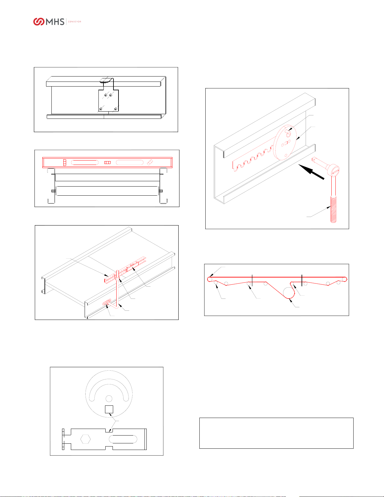
CONVEYOR SET UP
1. Place each bed in position per layout
drawing.
2. Splice beds together as shown below:
CRUZBELT SPLICE
3. Set final elevation and level unit. Conveyor
must be level side-to-side as shown:
CONVEYOR MUST BE LEVEL
LEVEL
4. Tighten support bolts and anchor to floor.
5. Install any required guard rail as shown:
LOWER BRACKET
ARM
UPPER BRACKET
SPLICE
GUARD RAIL
GUARDRAIL
6. Square end pulleys and snubbers using
alignment holes. Move cam or snubber
bracket until the 3/8” square alignment hole
is in line with the 3/8” square in the bed
frame. A 3/8” key stock can be inserted into
the holes for quick alignment.
ALIGNMENT
HOLES
ALIGNMENT
I
7. Locate drive. Remove both black plastic
drive shrouds and quick-release pins. Use a
3/8” ratchet extension in the square hole of
one football bracket to roll the take-up as
shown. (NOTE: no sockets are needed, just
the 3/8” extension)
TAKEUP
PIN
3/8" RATCHET
W/EXTENSION
FOOTBALL
BRACKET
8. Thread belt through conveyor. Labels on
drive beds and end beds show specific
threading. A general belt path is shown
below:
DRIVE PULLEY
RETURN
IDLER
SNUBBER
END PULLEY
TAKE-UP PULLEY
THREADING
END BED DRIVE BED END BED
9. Pull belt ends together and insert lacing pin.
A belt puller may be needed to draw the
ends together.
10. Tension belt by rolling a football bracket
away from the motor. A standard 3/8” drive
ratchet will provide correct belt tension with
ease. Do not over tension the belt by using
a “cheater bar” on the ratchet. Belt should
be just tight enough to drive the product.
11. Replace quick-release pins into both football
brackets. One bracket may need to be
aligned slightly to insert the pin. Replace
drive shrouds.
CAUTION
Do not run the conveyor without replacing
both quick release pins.

CRUZbelt
12
E0032544Rev090710
ELECTRICAL
WARNING
All electrical controls must be installed, wired, and
connected by a licensed electrician.
All motor controls and wiring must conform to
the National Electrical Code as published by the
National Fire Protection Association and
approved by the American National Standards
Institute, Inc. In addition, since specific
electrical codes vary from one area to another,
be sure to check with the proper authorities
before starting the electrical wiring.
The voltage of the motor will be stamped on the
name plate. This voltage must match available
voltage. Consult the wiring diagram on the motor for
proper connections. If the motor on a single
direction conveyor runs the wrong direction, the
leads must be switched to reverse rotation.
WARNING
Motor must be connected to the voltage
listed on the name plate.
Consult the wiring diagram of the inside cover of the
starter and pushbutton for the proper electrical
connections.
Three phase drives require transformers to reduce
the pushbutton and control circuit to 115 volts. If
primary voltage is changed, the transformer must be
changed according to the wiring diagram found on
the transformer.
NOTE
All controls equipment is covered by the original
manufacturer’s warranty.
NEMA enclosure ratings are as follows:
•NEMA 1- Indoor use, provides protection
against contact with internal components.
Suitable for use in warehouse and
distribution environments.
•Gasketed NEMA 1- Same use as NEMA 1,
but with additional protection against dirt and
dust.
•NEMA 3- Outdoor use, designed to keep out
rain and dust.
•NEMA 4- Indoor and outdoor use, designed
to keep out rain and dust.
•NEMA 12- Indoor use, provides protection
against dust, dirt, oil seepage, and dripping
of non-corrosive liquids. Suitable for use in
industrial environments.
•NEMA 13- Indoor use, provides protection
against dust, dirt, sprayed oil and non-
corrosive liquids.
CONTROLS – SAFETY GUIDELINES
The following are basic conveyor control safety
guidelines for common controls equipment.
WARNING
All safety devices, including wiring of electrical safety
devices, shall be arranged to operate in a “fail safe”
manner. If power failure or failure of the device
occurs a hazardous condition must not result.
START-UP WARNING HORN:
Ideally, all conveyors should be within sight of the
conveyor start button. This allows the operator to
verify no one will be in danger when the conveyor
starts.
An audible warning device is required if all conveyor
cannot be seen from the start button location. It
could be a horn, buzzer, or bell unique to that
conveyor for that location. It must be loud enough to
be head at any point of the conveyor being started.
It should sound for five seconds after the start button
is pushed, prior to the conveyor starting. Any
auxiliary equipment such as vertical lifts, turntables,
etc. must be included in the warning circuitry.
All conveyors that start and stop automatically
should be marked with the appropriate labels.
Adding a warning horn to conveyors that start
unexpectedly is recommended.
START PUSHBUTTONS:
Start pushbuttons should be the flush type or
guarded to prevent accidental activation. They
should be provided with a legend plate defining
which conveyors will be started.
STOP PUSHBUTTONS:
Stop pushbuttons should be the extended type so
that any contact will result in activation. They should
have a legend plate defining which conveyors will be
stopped.

CRUZbelt
13
E0032544Rev090710
OPERATOR CONTROLS:
Additional operator controls should be designed into
the system with the same guidelines that go into
start and stop pushbuttons. Devices which are
repeated on multiple control stations, such as
emergency stops, should be located at the same
relative location on each station. All operator
controls shall be clearly marked or labeled to
indicate the function controlled.
EMERGENCY STOPS:
All locations where an operator must work directly at
the conveyor should be protected by an emergency
stop. Operators should not have to leave their
position to actuate the emergency stop.
Conveyor in areas of high pedestrian traffic should
also be protected by emergency stop devices.
Emergency stops should be located throughout a
system. Their location will depend on likely
observation points and areas with special devices or
interfaces between equipment.
Emergency stops can be a pushbutton or cable
operated switch. The pushbutton should be
mushroom-style and red. The pushbutton must
require resetting after actuation. Cable operated
switches should trip by pulling the cable and require
resetting at the switch.
An emergency stop should normally stop all
conveyors in the system. Very large systems may
involve dividing the system into zones of control.
Actuating an emergency stop must drop out the start
circuit and require restarting the system using the
start pushbutton.
WARNING
Before restarting a conveyor which has been
stopped because of an emergency, an inspection of
the conveyor shall be made and the cause of the
stoppage determined. The starting device shall be
locked out before any attempt is made to correct the
cause of the stoppage.
CONTROLS LOGIC:
Solid state controls logic devices, such as
programmable controllers, are used extensively for
conveyor control. They are very reliable, but a
hardware failure or software bug could cause an
output to malfunction. For this reason, start circuits,
warning horn circuits, and emergency stops should
usually be configured using conventional relay logic.
SAFETY SWITCHES:
All conveyor control cabinets and motors should be
provided with safety (or disconnect) switches.
These switches must have provisions for padlocking.
As required for maintenance, equipment should be
locked in the OFF position.
SPECIAL DEVICES:
Special devices and equipment such as vertical lifts,
turntables, high speed conveyors etc. all have
unique design and safety requirements and should
be evaluated individually.

CRUZbelt
14
E0032544Rev090710
BELT TRACKING
WARNING
Only qualified personnel should be allowed to track
the belt. Use caution since conveyor must be run
during the tracking procedure.
ALL PULLEYS AND SNUBBERS MUST BE
SQUARE and conveyor must be level prior to
tracking the belt. Align the 3/8” square in the cam
and snubber bracket with the corresponding square
in the bed frame. (See “Conveyor Set-up” section).
Conveyor must be wired to run the correct direction.
Belt should be tensioned tight enough to drive the
heaviest product.
Belt tracking is accomplished using either the
tracking cams or snubber tracking brackets.
I
TRACKINGBRKTS
TRACKING CAM
SNUBBER TRACKING BRACKET
ALIGNMENT
HOLES
Snubber tracking brackets are located near the end
of the conveyor on the return belt snubber and near
the middle of noseovers. Tracking cams are located
on the end pulleys, the drive snubber, and near the
middle of noseunders.
CAM
BRKT
CAM
BRKT
CAM
DRIVE
NOSE
UNDERNOSE
OVER
BRKTLOCATION
Turn the tracking cam with a 3/8” ratchet as shown:
TURNCAM
3/8" RATCHET
3/8" EXTENSION
NO SOCKET
Tracking scenarios:
(Note: “FLOW” refers to belt flow direction, not
necessarily product flow)
FLOW
BELTTRAVEL
BELTTRAVEL
FLOW
FLOW
FLOW
BELTTRAVEL
BELTTRAVEL
FLOW
BELTTRAVEL
FLOW
BELTTRAVEL
END PULLEY,
NOSEUNDER SNUBBER
NOSEUNDER SNUBBER
END PULLEY,
DRIVE
SNUBBER
SNUBBER
DRIVE
RETURN SNUBBER,
NOSEOVER SNUBBER
NOSEOVER SNUBBER
RETURN SNUBBER,
TRACKING
NOTE
Belt moves toward the end of the pulley
that it contacts first.

CRUZbelt
15
E0032544Rev090710
CRUZbelt is slightly different to track than other
conveyor. Since the belt is only 7/16” narrower than
the between frame dimension, some belt contact
with the side frame is expected. However, the belt
must not be allowed to contact the frame near any
end pulley or snubber.
CAUTION
Belt must not be allowed to contact the side frame
near an end pulley or a snubber.
Some basic tracking information:
•The belt moves TOWARD the end of a
pulley it contacts first.
•Use snubber tracking brackets before using
tracking cams. End pulley tracking is used
as a last resort.
•Tracking brackets and cams only affect belt
DOWNSTREAM of the device. Find the
nearest bracket or cam upstream from the
problem area and adjust as shown.
•Adjust bracket or cam slightly and watch belt
for several revolutions before continuing.
CAUTION
CRUZbelt conveyor must be used with
mono-filament belting. Use of any other belting
will damage conveyor. Consult your MHS
Conveyor distributor for belt specifications.

CRUZbelt
16
E0032544Rev090710
COMMISSIONING OF EQUIPMENT
GENERAL
Commissioning of the equipment can best be
defined as the final adjustments and test of the
installed equipment required for its proper operation.
The need for commissioning is inherent, since the
individual components of equipment are brought
together at the installation site to operate as a
system.
Mechanical and electrical commissioning is most
often carried out simultaneously. Commissioning
must simulate the actual operation of the system as
close as possible to demonstrate the ability to
perform reliably at the specified rate in the
prescribed operational sequence.
During the Commissioning Phase, it is necessary to
load the equipment with product to be conveyed,
which provides the means of detecting those areas
requiring adjustment. Personnel will be required to
support operational functions. This may serve as
part of operator training and familiarity with the
system. During the commissioning activity, special
attention should be directed toward personnel
safety. No unnecessary risks should be taken that
would endanger the safety of any personnel. All
personnel must familiarize themselves with all safety
features of the system such as emergency stops
and motor disconnects.
MECHANICAL STATIC CHECKOUT
(No power to the conveyor.)
1. Follow the belt path through the entire conveyor.
2. Visually inspect the installation. Is the conveyor
straight? Is the conveyor reasonably level from
side to side? From end to end?
3. Check guard rail clearance to product.
4. Eliminate all catch points.
5. Check conveyor elevations.
6. All bolts and set screws tight.
7. Check product clearance to overhead structures.
8. Simulate all operational functions with actual
product.
9. All guards in place with proper clearance.
10. All OSHA required guards in place on walkways,
catwalks, ladder-ways, floor openings, etc.
11. All labels and warning signs in proper place,
unobstructed.
MECHANICAL DYNAMIC CHECKOUT
(Power to the conveyor, but no product on it.)
1. Turn the motor ON. With the belt moving make
sure each belt has proper tension.
2. Check the belt tracking.

CRUZbelt
17
E0032544Rev090710
PREVENTIVE MAINTENANCE
GENERAL:
Preventive maintenance includes lubrication,
adjustment of equipment, and replacing or repairing
parts before failure.
All maintenance should be recorded in a log. This
should show what was serviced and when. The log
can then be used to trouble-shoot any systemic
problems.
WARNING
Do not perform any maintenance until the conveyor
power is locked out and cannot be turned on by any
person other than the one performing the
maintenance. If more than one person is working on
the conveyor, each person must have a lock on the
power. Any air lines in the work area should also be
turned off.
Make sure personnel are clear of the conveyor
before starting. All guards must be in place before
starting.
GEARMOTOR:
The drive unit should be checked monthly. Check
the motor gear case for leaking seals. Check fluid
level and fill with ISO VG220 mineral oil if necessary.
Check breather on the gear case.
CHAINS AND SPROCKETS:
Chains and sprockets should be checked monthly.
If either the sprockets or the chain are worn, both
should be replaced. Sprockets must be checked for
alignment with a straight edge. Clean the chain with
a non-flammable solvent and lubricate with 30W
synthetic oil. A brush is recommended for oil
application.
Check chain tension after initial run-in and then
monthly. Tension should be slightly slack, as
shown:
3/16"-1/4"
CHAIN
3/16"-1/4"
ALLOWABLE CHAIN SLACK
ROLLERS:
Inspect rollers periodically for debris build-up.
BELTS:
Belts normally need very little care. Clean monthly
with compressed air or a stiff brush. Clean bi-
annually with water and detergent.
CAUTION
Do not use petroleum-based products
to clean the belt.
REGREASABLE BEARINGS:
The drive unit and power take-off have regreasable
bearings. These bearings should be lubricated
every six months.

CRUZbelt
18
E0032544Rev090710
MAINTENANCE SCHEDULE
Maintenance intervals will vary site by site.
Establish short intervals at first, then lengthen if
possible. The following is based on 8 hours per day,
5 days per week under normal conditions:
DAILY
•Listen for unusual noises
•Inspect conveyor for debris
•Check belting for build up or debris
•Verify all pulleys and rollers turn free
•Verify all guarding is in place
•Check for oil leakage
•Check for unusual vibration
•Check for loose bolts or parts
WEEKLY
•Inspect belt for proper tracking and tension
•Inspect belt lacing
•Inspect belt edges for fraying
•Inspect bearings and gear motor for
excessive heat or noise
•Clean breather vent on gear motor
•Check operation of all electrical controls
•Inspect motor mounting bolts
MONTHLY
•Clean chains and sprockets. Lubricate with
synthetic 30 weight oil.
•Check chain tension and alignment
•Clean belt with compressed air or stiff brush
•Check gear motor oil level
•Check pulley lagging for signs of wear
SEMI-YEARLY
•Clean belt and all surfaces with detergent
and water
•Grease drive pulley and power take-off
bearings.
YEARLY
•Inspect bolts for tightness
•Check for plumb and level.
•Touch up paint
TWO YEARS OR 10,000 HOURS
•Drain and fill gearmotor with ISO VG220
mineral based oil.
CAUTION
Verify all tools and foreign objects have been
removed from conveyor. Check that all guards have
been replaced and bolts have been retightened.

CRUZbelt
19
E0032544Rev090710
TROUBLESHOOTING GUIDE - BELT
Problem Belt Possible Cause Remedy
1. Belt stopped or moving
slower than normal,
reducer output shaft is
turning properly and all
electrical components
are operating normally.
Chain is loose and is skipping
sprocket teeth Tension chain. Check sprocket
alignment, check for worn teeth.
Belt has separated Replace the entire belt or cut out
damaged portion and add new
piece with extra lacings.
Bearings have failed Locate and replace the bearings
Belt slipping on drive pulley See #2 below
Belt lacing pulled out See #3 below
Improper belt tension Re-tension take-up pulley
Drive sprocket loose on shaft Re-tighten sprocket and check for
shaft wear
Belt jammed due to obstruction Check belt path and remove any
obstruction
Belt mistracked on return side Reference Belt Tracking procedure.
2. Belt slipping on drive
pulley Take-up pulley not adjusted
properly Adjust take-up cam in small
increments. Do not over-tighten.
Drive pulley lagging or pulley side of
belt is slippery
Replace pulley if lagging worn
smooth. If slipping is caused by
foreign substances in the lagging or
bottom of belt, clean by scraping or
wire brushing. Do not use solvents
on belt or pulley lagging.
New belt has stretched Normal. Re-adjusted take-up.
Seized end pulley or snubber roller
bearings Check and replace as required
Load too heavy Remove as required. Re-analyze
needs.
Belt threaded improperly Check belt path per this manual
3. Belt lacing pulling out Tension too high Reduce belt tension at take-up
pulley
Obstruction Remove obstruction
Lacing worn out Replace lacing with Clipper #36SP

CRUZbelt
20
E0032544Rev090710
TROUBLESHOOTING GUIDE - BELT
Problem Belt Possible Cause Remedy
4. Belt runs to one side Rollers preceding and at trouble
point are not square
Check alignment of pulleys and
rollers. Adjust pulleys and rollers as
required. See Belt Tracking section
of this manual.
Build-up of foreign material on
rollers and pulleys Clean rollers and pulleys. Do not
use solvents.
Conveyor not level Level conveyor bed
Bowed belt If belt is new, load tension may
straighten it. Otherwise, replace.
Pulley bearing set screws loose
allowing pulleys to walk to one side
Loosen belt and reposition the
pulley centered in the frame.
Retighten the set screws and center
the belt on the pulley.
Worn bearings Check and replace.
Belt not joined securely at lacing Re-cut belt ends square and re-
lace.
Off center loading Correct loading conditions.
5. Rips at or near edge of
belting Obstruction Remove obstruction
Belt running against conveyor frame See Belt Tracking section of this
manual.
Loose lacing Check lacing for tightness and
general condition. Check if belt is
chamfered on corners.
6. Conveyor belt jerks
during operation Too much slack in drive chain which
is jumping the sprocket Adjust chain tension, check for worn
sprockets.
Chain climbing the sprocket See “Chains & Sprockets” #8
7. Gouging of top cover Obstruction Locate and remove obstruction
Damaged return idler or snubber
pulley
Verify return idlers and snubber
pulleys are spinning freely and have
no material build-up.
8. Severe wear on drive
pulley side of belting Belt slipping on drive pulley See #2 above
Frozen or sticking rollers or pulleys Replace bad pulleys or rollers
Slider bed damage or misalignment Check slider bed for smoothness
and alignment at joints
9. Excessive belt
stretching Tension too great Reduce belt tension by take-up
adjustment
Table of contents
Other MHS Boilers Accessories manuals


