MHS Boilers Aqua Line T1 User manual
Aqua Line
Installation Guide
Hot water radiant panels
5
FIVE YEAR
WARRANTY

2
Read this document before
installing the appliance
Warning
Incorrect installation, adjustment, alteration, repair or maintenance work may lead to material
damage or injury. All work must be carried out by certied, qualied professionals. If the
appliance is not positioned in accordance with the instructions, the warranty shall be rendered
void. This appliance is not intended for use by children or persons with a physical, sensory or
mental handicap, or who lack the required experience or expertise, unless they are supervised
or have been instructed in the use of the appliance by somebody who is responsible for their
safety. Children must be supervised to ensure that they do not play with the appliance.
If the manual refers to an image or table, a number will be shown between square brackets, for
example [3]. The number refers to images and tables at the back of the manual with the stated
number.
1.0 General
[1] Panel dimensions [6] Heat delivery table
[2] Overview, water side connection [7] Minimum mass ow
[3] Panel structure [8] Transporting the panel
[4] Overview, covers [9]/[10] Mounting instructions
[5] Selection and design advice [11] Mounting to the ceiling
1.1 Application
The Aqua Line heats a room by means of radiant heat. Warm water is pumped through the
pipes in the radiant panels. This makes the panel warm and heat is then radiated. The Aqua Line
can also be used for cooling: cooled water is pumped through the pipes making the panel
cold and cooling the environment. Condensation must be prevented from forming. The minimum
water temperature therefore depends on the level of atmospheric humidity in the room.
Subject to change
The manufacturer is committed to constantly improving its products and reserves the right to
make changes in the specications without prior notice. The technical details are considered
correct but do not form the basis for a contract or warranty. All orders are accepted according
to the standard terms of our general sales and delivery conditions (available upon request).
Key table [6]
T = type of panel
K = medium upper temperature
P = number of pipes per distributor
3
EN
Twi + Twu
K = ————— – T omg
2

Key table [7]
TR = water return temperature in °C
W = minimum mass ow of water per pipe in kg/h
Key table [9]
LB = section length
U = section expansion in mm
Tgem = average water temperature.
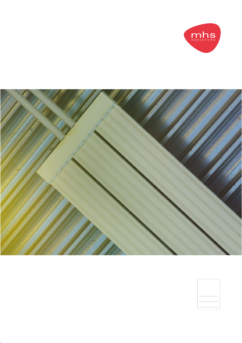
1.2 Panel type + dimensions: [1]
T Type G Thicknesses of material
A Length H Weight per 4m (empty)
B Width I Weight per 6m (empty)
C Number of pipes J Water content per 4m
D Pipe diameter K Water content per 6m
E Thickness of pipe wall L Max. temperature
F Height of radiation hood (radiation panel) M Max. operating pressure
1.3 General warnings
Incorrect installation, adjustment, alteration, maintenance activity or repair may lead to material
or environmental damage and/or injuries. The appliance should therefore be installed, adapted or
converted by a skilled and qualied installer, taking into account national and international
regulations. A faulty installation, adjustment, alteration, maintenance activity or repair shall render
the warranty void.
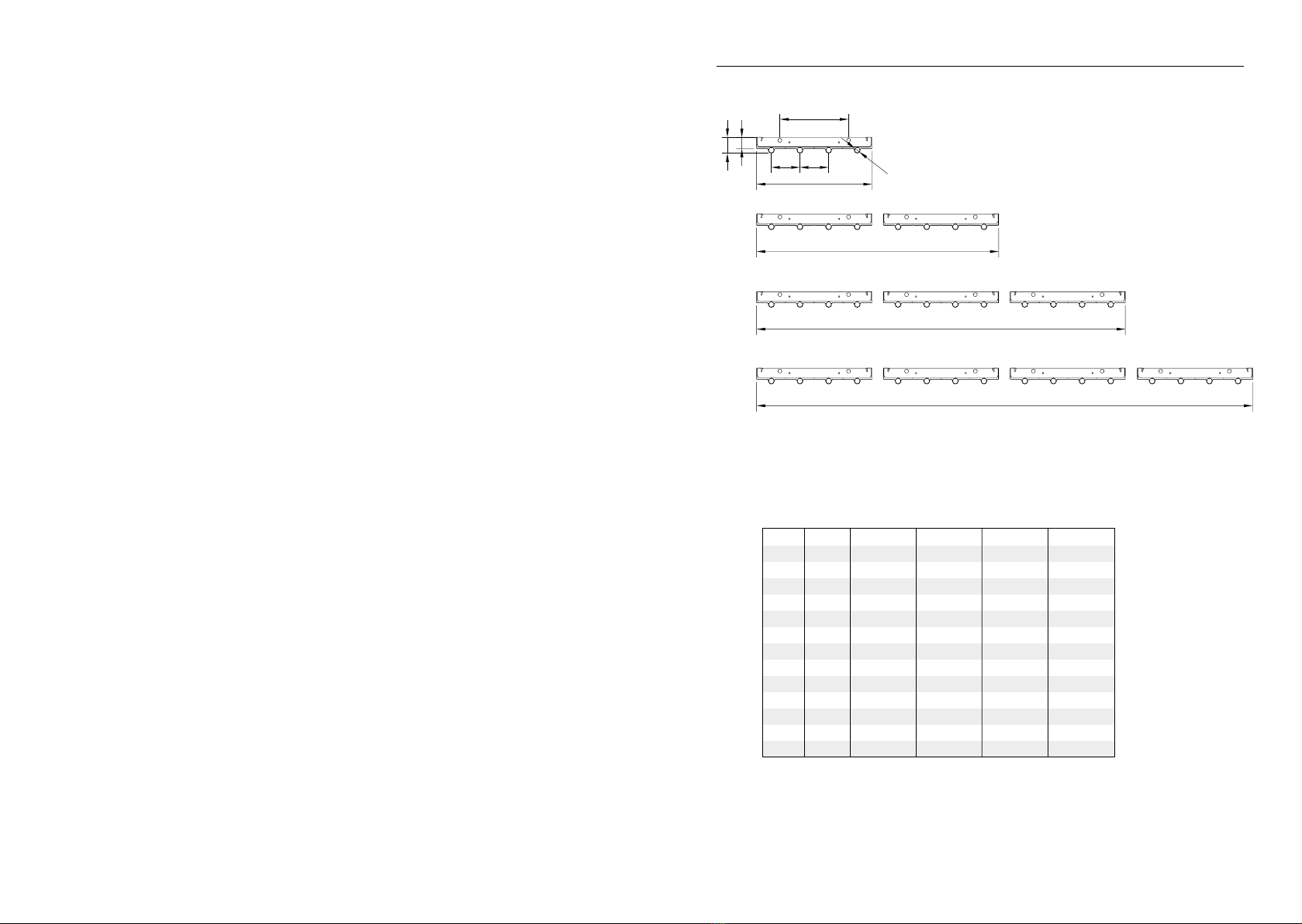
1.4 Description of the Aqua Line panel [3]
A radiation panel is made up of multiples of four pipes attached to a proled steel plate. Because
the pipes are actually located within the prole of the steel plate, there is a large contact area.
This also benets the delivery capacity. The top of the radiation panel should be insulated on the
upper side using the loose insulating material supplied (to be tted by you). This will restrict
undesirable upward radiation. The insulation strips must be cut to length manually.
1.5 Construction of the panel [3]
1 Reector
2 Water-carrying pipe
3 Distributor
4 1” connections, water side
5 Mounting set (prole and carbine hooks)
6 Push-on connectors (optional)
7 Insulating material
8 De-aeration connection ½” (de-aeration nipple is not included in MHS’s scope of supply)
The panels are delivered in standard lengths of 4 or 6 metres. Longer lengths can also be created
by joining the panels together using the push-on connectors [3]. Note the water ow in this case.
In addition to the length, the width can also be adjusted. The distributors are also installed using
the push-on connectors. If required, the push-on connectors can be concealed using a reector
concealing cover to create a neat nish [4].
4
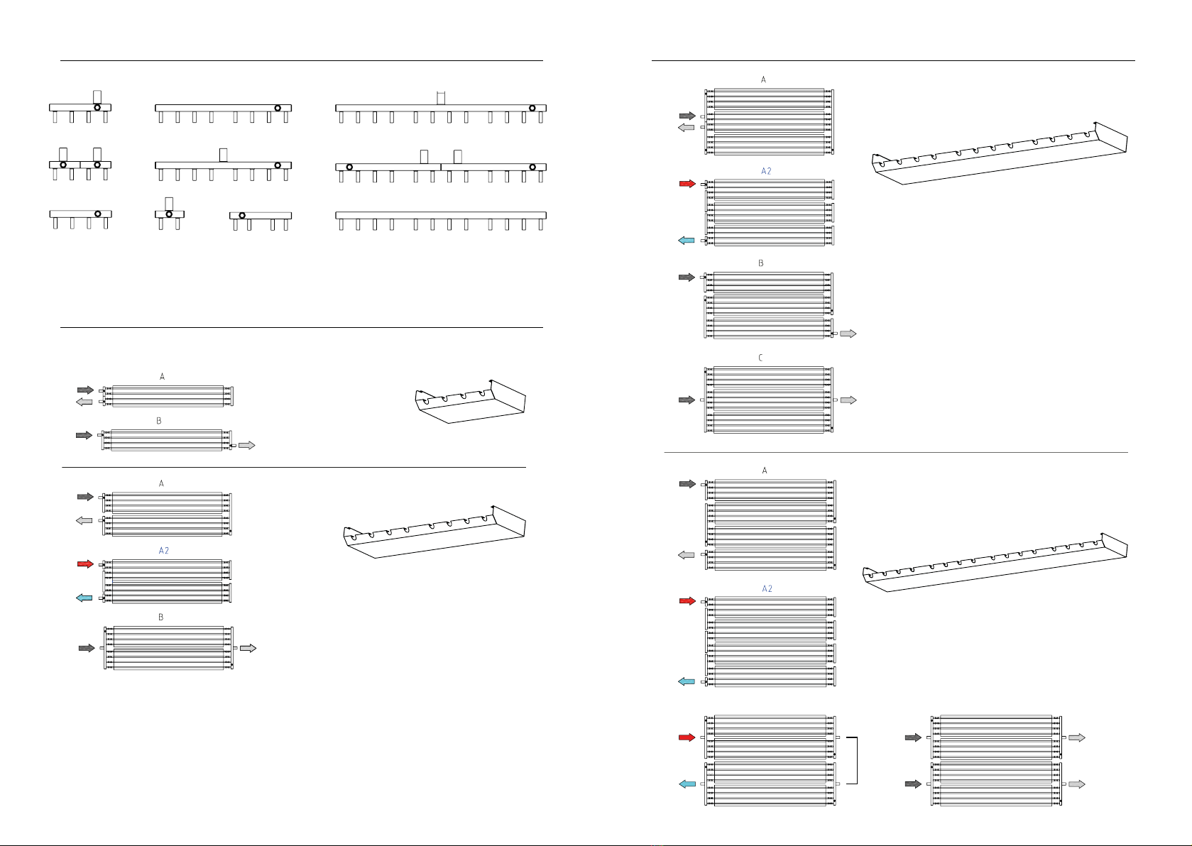
2.0 Selection and design advice [5]
In order to heat the room evenly, it is important to follow the steps below. These calculations
determine the type of panel, the panel length, distributors and the pressure drop. In connection
with the water side pressure drop and panel expansion, we advise you to keep the maximum
section length below 46 metres.
2.1 Signs and symbols
B = Width of the room q = Panel heat output per section length
H = Height of the room Q = Heating requirement
Hm = Installation height Tomg = Ambient temperature
K = Upper temperature Twi = Water temperature in (feed)
L = Length of the room Twu = Water temperature out (return)
LB = Section length ∆T = Temperature variation
Ltot = Total section length Qpp = Heat capacity per panel (table) [6]
nsp = Number of radiation sections npp = Number of panel lengths needed
n = Number of pipes per group R = Pressure drop per pipe per metre of panel
mpb = Mass ow per pipe Z = Distributor pressure drop
m = Mass ow per panel length
2.2 Steps to be followed
1. Determine the width, height and type of panel for the space. [5]
Twi = 65ºC
Twu = 50ºC
Tomg = 18ºC (Temp. in the room)
2. Determine the section length: [5]
LB = L – 3m
L
B = 45 – 3 = 42m
NOTE!
Only 4 or 6 metre panels may be used.
42m is divisible by 6. This results in 7 panels, each 6 metres in length
See table [9]
3. Determine the installation height:
Hm= H – 0.5m
Hm = 5 – 0.5 = 4.5m
This is also the optimal distance from the centre point of each panel. [5]
5
EN

4. Determine the upper temperature:
Twi + Twu
k = ————— – T omg
2
65 + 50
k = ————— – 18 = 39 Kelvin
2
This value can be used to look up the heat capacity of the panel in the table (heat delivery
table) [6] (type 1,2,3 and 4). This is the value Qpp.
(T=1) Qpp = 132 W/m (heat output table) [6]
5. Determine the heat delivery for a single length:
q = LB x Qpp
q = 42 x 132 = 5544 W/section
6. Determine the temperature variation of the water:
∆T = Twi – Twu
∆T = 65 – 50 = 15 K
7. Determine the mass ow of the liquid in one panel length:
m = (q/∆T ) x 0.86
5544
m = ———— x 0,86 = 318 kg/h
15
8. Determine the mass ow per pipe:
mpb = m / n
1 section consisting of a Type 1 panel. [2]
Flow may take place through 4 pipes or 2 pipes. The mass ow must be calculated for these
two situations in order to connect the panel on the water side.
mpb = 318 / 4 = 79,5 kg/h (B)
318 / 2 = 159 kg/h (A)
9. Check the minimum mass ow using the appropriate table [7] (68 kg/h). The calculated value
must be higher in order to achieve turbulent ow through the pipes. This then gives the
correct number of distributors [2].
6
10. Determine the pressure drop on the water side [2]:
T1 Single side Sit.A ∆P = (Lb x R1) + (Lb x R2) + Z
T2 Single side Sit.A ∆P = (Lb x R1) + (Lb x R2) + Z
T3 Single side Sit.A ∆P = (Lb x R1) + (Lb x R2) + Z
T4 Single side Sit.A ∆P = (Lb x R1) + (Lb x R2)+ (Lb x R3) (Lb x R4)+ Z
T1 Alternating sides Sit.B ∆P = (Lb x R1) + Z
T2 Alternating sides Sit.B ∆P = (Lb x R1) + Z
T3 Alternating sides Sit.B ∆P = (Lb x R1) + (Lb x R2)+ (Lb x R3) + Z
T3 Alternating sides Sit.C ∆P = (Lb x R1) + Z
R = Water resistance per panel length in Pa/m
Z = water resistance in Pa for both distributors
R = x 196
Calculation example: T=1 , 79,5 kg/h (B)
∆P = LB x R +Z
R = 41 Pa Z = 202 Pa
Determine the pressure drop for both panel groups:
∆P = 42 x 41 + 202 = 1924 Pa
3.0 Transport
Leave the panels on the pallet for as long as possible.
Ensure the pallet does not bend too much (do not move the pallet using a pallet truck).
To prevent bending, move the panel rotated/turned by 90º [8].
Panels must be stored in a dry environment.
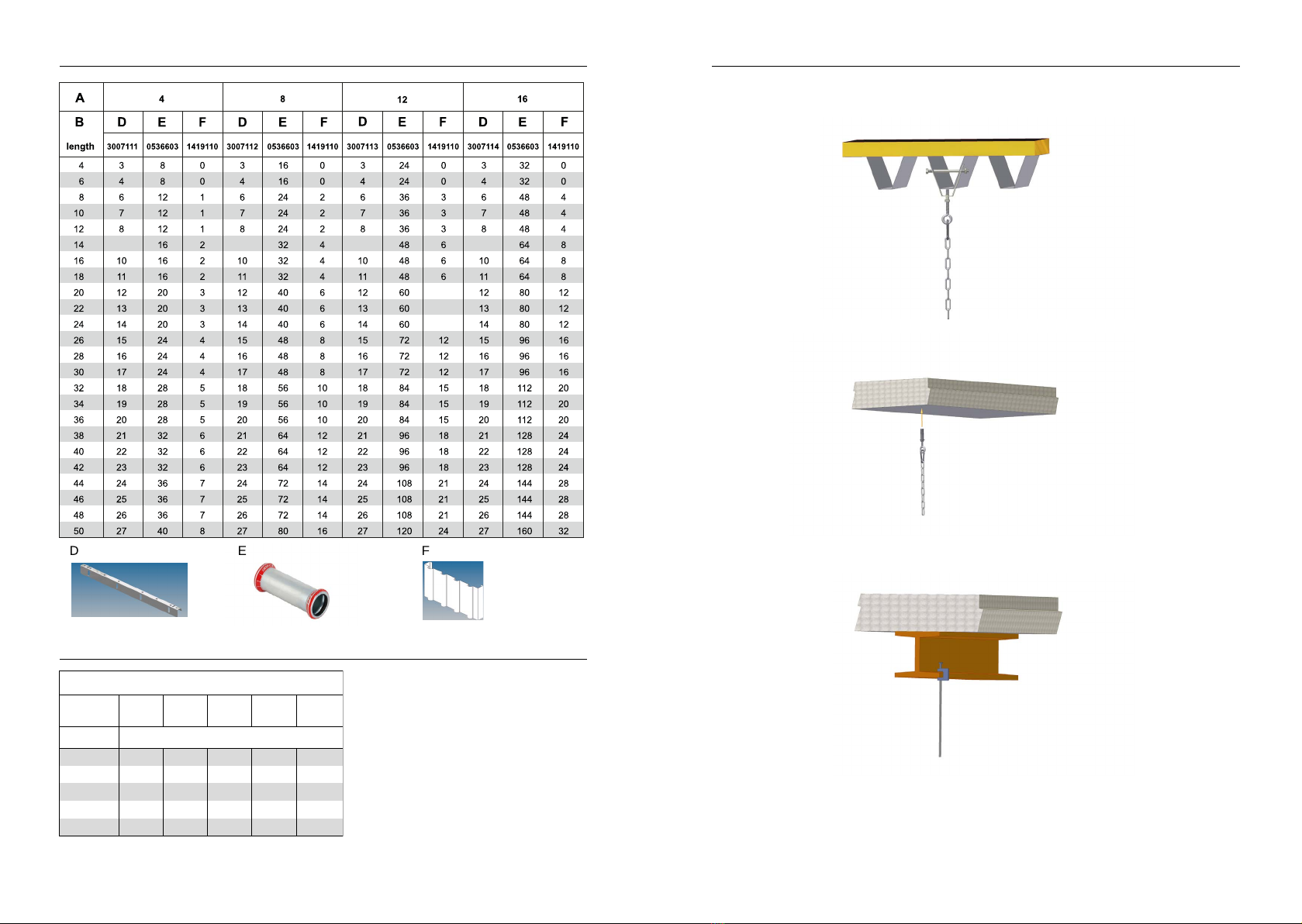
4.0 Mounting panels [9][10]
4.1 Mounting instructions [9]
– The panel must be placed at a minimum height of 2m above the oor.
– The measurement from the centre point of the panels must not be greater than the height
above the oor. [5]
– Distance between the installation proles max. 2 metres [9].
– Suspend the panels in such a way that they can expand freely lengthways [9][10].
Key table [10]
A = Number of tubes
B = Section length
D = Number of brackets
E = Number of press links
F = Cover between panels
m
Z = x 2000
1000
(
(
2
m
pipes
173
(
(
2
7
EN
l2 = Expansion in mm
l1 = Section length mm
α = Linear expansion coefcient of steel => 11.7x10⁻⁶
Tw gem = Average water temperature.
Tomg = Temperature in the room.
Determine the expansion of 1 section length:
l2= l1 x (1 + α x (Tw gem – Tomg)
l2 = 42000 x (1 + 11.7x10⁻⁶ (57.5 – 0))
l2 = 42028.3mm
Expansion U = 28.3mm
Expansion table [11].
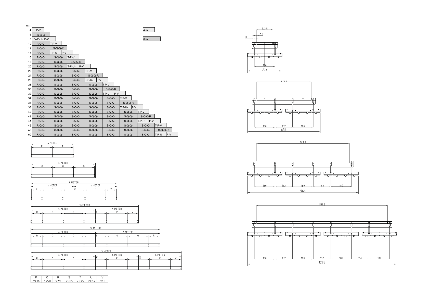
4.2 Order of installation. [4]
– Fit the suspension points [9][10]
– The panels can be mounted directly to threaded rod or hung from chains [12].
– Join the panels together using the push-on ttings.
– Install the distributors [3].
– Add the insulation.
– Place covers, if required, on the panel connections and distributors [4].
5.0 Start-up
Fill the installation with water, bleed the pipes and rinse through to remove any contamination.
Adjust any ow controls. Ensure that the water mass ow does not fall below that indicated in the
table [7]. If the water mass ow is lower, output cannot be guaranteed.
Key table [7]
TR = water return temperature in °C
W = minimum mass ow of water per pipe in kg/h
6.0 Maintenance
Clean the panels regularly, check them for leaks and check the suspension points. If applicable, ask
a qualied installer for maintenance advice.
8 9
1298
966
634
302
ø15
180
aa
42
30
[1]
T 1 2 3 4
A m 4/6 4/6 4/6 4/6
B mm 305 636 968 1300
C n 4 8 12 16
D mm 15 15 15 15
E mm 1,0 1,0 1,0 1,0
F mm 42 42 42 42
G mm 0,5 0,5 0,5 0,5
H kg 12,2 24,4 36,6 49,2
I kg 18,2 36,4 54,6 72,8
J dm3 2,12 4,24 6,36 8,48
K dm3 3,19 6,38 9,57 12,76
L ºC 120 120 120 120
M bar 8 8 8 8
1110
[1]
[2]
0650265 0650273 0650285
0650267 0650275 0650287
0650263 0650252 0650261 0650283
1419111
1419112
1419113
1419114
BC
[2]
1419111
1419112
1419113
1419114
BC

[5][3]
7
[4]
1 8 4
3
6
2
5
12 13

[7]
[8]
56
TR W
°Ckg/h
30 99
35 88
40 81
45 73
50 68
55 61
60 58
65 53
70 50
75 47
80 44
85 41
90 39
95 37
100 35
[6]
Watt/m to EN 14037 1-3
Me dium TMe dium P
overtem
p
overtem
p
K1234 K48 12 16
1154769521428 1904 115165330494659
110451 90313541806110 156312 468624
1054278551282 1709 105147295442590
100403 80712101613 100139 278417 556
95 3807591139 1518 95 131261392522
90 356712 1068 1424 90 122244 367489
85 3336669981331 85 114228342456
80 310619 9291239 80 106212 318423
75 2875748611148 75 98 196293391
70 264529 7931058 70 90 180270 360
69 2605207801040 69 88 177265353
68 256511 7671022 68 87 174260 347
67 2515027531004 67 85 170256341
66 247493 7409876684167 251335
65 24248572796965 82 164246329
64 238476 7149516481161 242322
63 23346770093463 79 158237316
62 229458 6879166278155 233310
61 22544967489961 76 152228304
60 220441 6618816074149 223298
59 21643264886459 73 146219292
58 212423 6358475871143 214286
57 20741562283057 70 140210280
56 203406 6098125668137 205274
55 19939859679555 67 134201268
54 195389 5847785466131 197262
53 19038157176153 64 128192256
52 186372 5587445263125 188250
51 18236454572751 61 122183244
50 178355 5337105060119 179239
49 17334752069449 58 116175233
48 169338 5086774857113 170227
47 16533049566047 55 111166221
46 161322 4836444654108 162215
45 15731447062745 52 105157210
44 153305 4586114451102 153204
43 14929744659443 50 99 149198
42 144289 433578424896145 193
41 14028142156241 47 94 140187
40 136273 409546404591136 182
39 13226539752939 44 88 132176
38 128257 385513384385128 171
37 12424937349737 41 83 124165
36 120241 361482364080120 160
35 11623334946635 39 77 116154
30 97 194291 38830326496128
25 78 15623531325 26 51 77 102
20 60 120180 2402019395878
15 43 85 12817115 14 27 41 55
14 15
[9]
16 17
19
[12]
18
[10]
[11]
999
9
9
9
9
U(mm)
LB(mm) 10.000 20.000 30.000 40.000 50.000
Tgem (˚C)
30 3,5 7,0 10,5 14,0 17,6
50 5,9 11,7 17,6 23,4 29,3
70 8,2 16,4 24,6 32,8 40,9
80 9,4 18,7 28,1 37,4 46,8
90 10,5 21,1 31,6 42,1 52,7

RC/0119/7371RC
SALES OFFICE - 0345 521 5666
MHS Radiators Limited, 3 Juniper West, Fenton Way, Southfields Business Park, Basildon, Essex SS15 6SJ
Tel: 0345 521 5666 Fax: 01268 888260
This manual suits for next models
3
Table of contents
Other MHS Boilers Heater manuals


